$13.50
Keypads are very handy input devices, but who wants to tie up 7 GPIO pins, wire up a handful of pull-up resistors, and write firmware that wastes valuable processing time scanning the keys for inputs? Let’s make the development process easier! The SparkFun Qwiic Keypad comes fully assembled and uses the simple Qwiic interface. No soldering, no voltage translation, no figuring out which I2C pin is SDA or SCL, just plug and go!
The Qwiic Keypad reads and stores the last 15 button presses in a First-In, First-Out (FIFO) stack, so you don’t need to constantly poll the keypad from your microcontroller. This information, then, is accessible through the Qwiic interface. Qwiic Keypad even has a software configurable I2C address so you can have multiple I2C devices on the same bus.
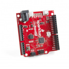
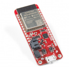
The SparkFun Qwiic Keypad does need a few additional items for you to get started; a Qwiic enabled microcontroller and a Qwiic cable. You may already have a few of these items, so feel free to modify your cart based on your needs.
If you're unfamiliar with jumper pads or I2C be sure to checkout some of these foundational tutorials.
Button Pad Hookup Guide
An introduction to matrix scanning, using the SparkFun 4x4 Button Pad.
|
Multiplexer Breakout Hookup Guide
How to use the 74HC4051 multiplexer breakout to drive eight LEDs, read eight button inputs, or monitor eight potentiometers.
|
Arduino Kepad Tutorials
|
The Qwiic Keypad utilizes the Qwiic connect system. We recommend familiarizing yourself with the Logic Levels and I2C tutorials (above) before using it. Click on the banner above to learn more about our Qwiic products.
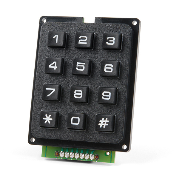
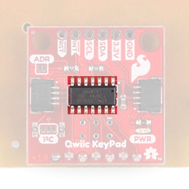
This is a basic 12 button keypad that has been designed for easy user input and functionality. The buttons are set up in a matrix format. This allows the ATtiny84 to scan the 7 output pins to see which of the 12 buttons are being pressed.
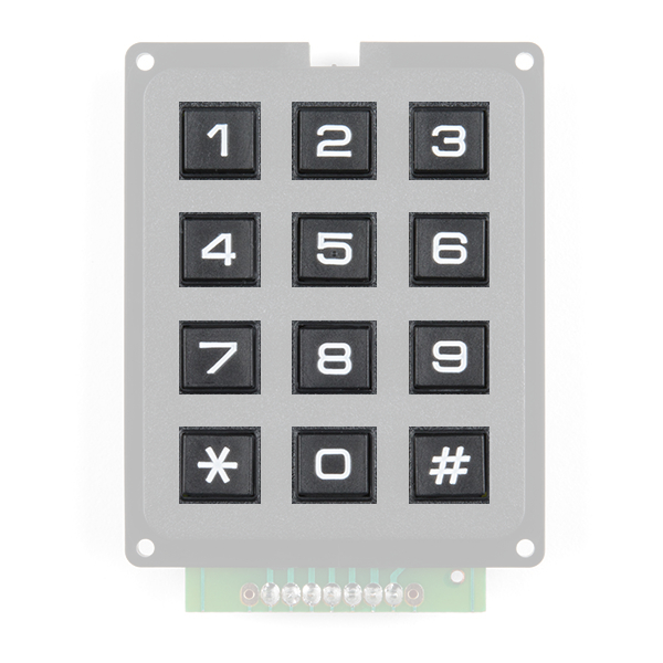
Each of the keypad's 12 buttons has been labeled 1, 2, 3, 4, 5, 6, 7, 8, 9, 0, *, and # and has been formatted to into the same layout as a telephone keypad. Each keypress resistance ranges between 10 - 150Ω.
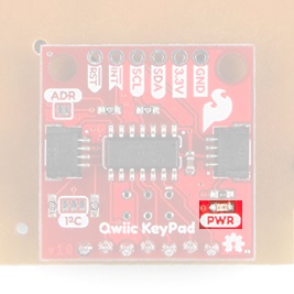
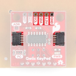
There is a power status LED to help make sure that your Qwiic Keypad is getting power. You can power the board either through the polarized Qwiic connector system or the breakout pins (PWR and GND) provided. The Qwiic system is meant to run on 3.3V, be sure that you are NOT using another voltage when using the Qwiic system. Qwiic Keypad is very low power and uses less than 4mA at 3.3V.
With the pre-installed firmware, the ATtiny84 acts as an intermediary (microcontroller) multiplexing the buttons for inputs. This allows the Qwiic Keypad to store the button presses in the FIFO stack to be read over I2C. Although the ATtiny84 has a wide voltage range, since this is a Qwiic product, users should power the board with the labeled 3.3V.
In the firmware, the FIFO stack stores the most recent 15 button inputs. Once the stack is full, any previous inputs are overwritten. The FIFO stack is manually incremented using the FIFO Command register. If there are no more values stored in the FIFO stack, the output will be 0x00 or Null.
In the firmware, the Qwiic Keypad’s I2C address is configurable so you can add a bunch of them to the same bus without collision issues.
Factory Default I2C Slave Address: 0x4B
| Address | Description |
|---|---|
| 0x00 | Default I2C Slave Address (Stored in EEPROM) |
| 0x01 - 0x02 | Firmware Version (MSB First) |
| 0x03 | Oldest Button Press (aka First-Out from FIFO stack) |
| 0x04 - 0x05 | Time in ms since the button was pressed (MSB First, 16-bit = Max Value of 65,535 ms). |
| 0x06 | FIFO Increment Command: Set bit 0 to increment FIFO. |
| 0x07 | Current/Set I2C Slave Address (Write). Stored in EEPROM. |
The simplest way to use the Qwiic Keypad is through the Qwiic connect system. The connectors are polarized for the I2C connection and power. (*They are tied to their corresponding breakout pins.)
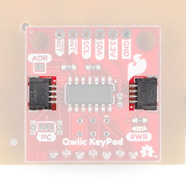
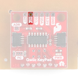
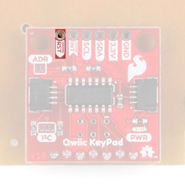
However, the board also provides six labeled breakout pins. You can connect these lines to the I2C bus of your microcontroller and power pins (3.3V and GND), if it doesn't have a Qwiic connector. The interrupt and reset pins are also broken out to use for triggered events.
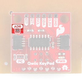
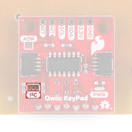
There are jumpers on the board allowing the user to select between different I2C addresses as well as to remove the pull up resistors from the I2C pins, if needed.
Bridging the I2C address jumper changes the slave address from the value stored in EEPROM to the I2C Jumper Default (or alternate): 0x4A.
Cutting the I2C jumper will remove the 2.2kΩ pull-up resistors from the I2C bus. If you have many devices on your I2C bus you may want to remove these jumpers. Not sure how to cut a jumper? Read here!
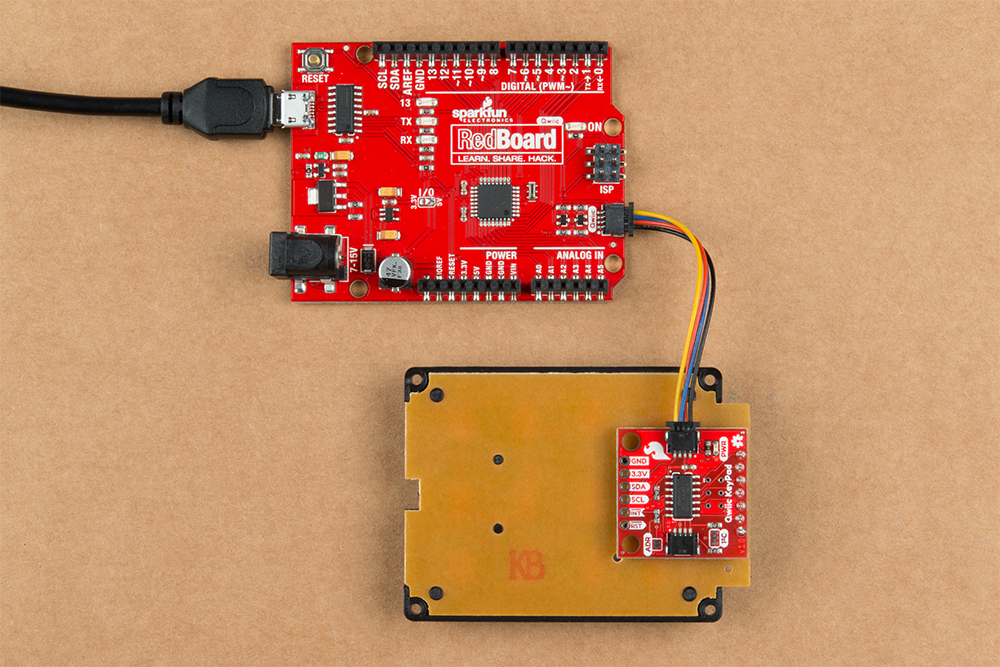
With the Qwiic connector system, assembling the hardware is simple. All you need to do is connect your Qwiic Keypad to Qwiic enabled microcontroller with a Qwiic cable. Otherwise, you can use the I2C pins, if you don't have a Qwiic connector on your microcontroller board. Just be aware of your input voltage and any logic level shifting you may need to do.
The easiest way to install the Arduino library is by searching SparkFun Qwiic Keypad inside the Arduino library manager. To manually install, head on over to the GitHub repository or feel free to download the library here!
The Arduino library is commented and the functions should be self-explanatory. However, below is a detailed list of the available library functions.
.begin() or .begin(Wire, deviceAddress)
Creates a connection to an I2C device over the I2C bus using the default or specified I2C address.
True- Connected to I2C device.
False- No device found or connected.
.isConnected()
Tries to connect to the device at the I2C address stored in the library.
True- Connected to I2C device.
False- No device found or connected.
.getVersion()
Returns a string of the firmware version number.
AAA - Firmware Version (Major)
BBB - Firmware Version (Minor)
.setI2CAddress(newAddress)
Changes the I2C address to newAddress. Once changed, the new I2C address is saved in the EEPROM of the Qwiic Keypad. Reconnects to device using new I2C address. (The new address is printed out in the Serial Monitor.)
Unasssigned 8-bit integer for device address.
Address: 0x##, where 0x## is the new I2C address.
Address Change Failure- Error output if the the microcontroller wasn't able to change the I2C address.
ERROR: Address outside 8-119 range- Error output if the new I2C address is outside the available range.
.getButton()
Returns the button at the top of the stack (aka the oldest button). In order to read this register for the first time, the FIFO needs to be incremented with the .updateFIFO() function first.
Value of the button.
.getTimeSincePressed()
This function reads the register that holds the time since the button (at the top of the FIFO stack) was pressed. In the firmware, the ATtiny85 actually responds to a request event (register read) and calculates the time since the button was pressed at that moment and updated the register. Like the .getButton() function, in order to use this function for the first time, the FIFO needs to be incremented with the .updateFIFO() function first.
Unasssigned 16-bit integer [0 - 65,535] for time since button was pressed (in milliseconds).
.updateFIFO()
Used to increment the FIFO stack- In the library, this function sets the updateFIFO register to 0x01. Once there is a request event (i.e .getButton() or .getTimeSincePressed()), the FIFO is incremented and the firmware clears the updateFIFO register back to 0x00.
There are six examples in the Qwiic Keypad Arduino Library to get you started with using Qwiic Keypad. These example files are named with self-explanatory titles, but in case you want more information, see the descriptions below.
Example1_ReadButton
This example connects to the Qwiic Keypad using the default I2C address saved in the library. The sketch loops through reading the register for the button at the top of the FIFO stack and incrementing the FIFO. The example then prints out the value over the Serial Monitor. The * is represented by a space and the # is represented with a new line (or carriage return).
Example2_ReadWithTime
This example operates exactly like the Example1_ReadButton, except the time since the button was pressed is outputted with the button that was pressed in the Serial Monitor. With a ~1 second delay between checks for button presses.
Example3_ChangeI2CAddress
This example connects to the Qwiic Keypad using the default I2C address set in the library and then prints out the I2C address and firmware version over the Serial Monitor. The sketch then, takes an input from the Serial Monitor to change the I2C address using a decimal value (DEC). Once the I2C address is changed, it is stored in the EEPROM of the Qwiic Keypad. After, the sketch connects to the keypad using the new I2C address and reads the registers for the firmware version again. The example then prints out those values over the Serial Monitor again.
Example4_I2CScanner
This example is from the I2C scanner example from the Arduino Playground webpage. The sketch scans for devices on the I2C bus and reports them on the Serial Monitor. This is useful for users who have forgotten the changed I2C address of their boards.
Example5_InterruptRead
This example operates exactly like the Example1_ReadButton, except that instead of constantly polling the keypad for button presses in the main loop, it responds to the interrupt (INT) pin. Utilizing an interrupt allows the MCU to execute a specific set of instructions (i.e. button read), outside of the main loop. For more details on interrupts, check out this tutorial on Processor Interrupts with Arduino .
Example6_Keycode
This example is a use case example, in which the user must input the correct key code: 1, 2, 3, 4. The sketch also implements a timeout, so that the user must input the correct code within 30 seconds.
The code for Example1_ReadButton connects to the Qwiic Keypad and prints out the value over the Serial Monitor. Below is a sample readout from the Serial Monitor using sequential button presses of: 1, 2, 3, 4, 5, 6, 7, 8, 9, *, 0, and #.

The code for Example2_ReadWithTime operates exactly like the Example1_ReadButton, except the time between since the last button press is printed. Below is a sample readout.
The code for Example3_ChangeI2CAddress connects to the Qwiic Keypad using the default I2C address set in the library and then prints out the I2C address and firmware version over the Serial Monitor. The sketch then, takes an input from the Serial Monitor to change the I2C address using a decimal value (DEC). Once the I2C address is changed, it is stored in the EEPROM of the Qwiic Keypad. After, the sketch connects to the keypad using the new I2C address and reads the registers for the firmware version again. The example then prints out those values over the Serial Monitor again. As shown in the sample readout below, the input value must between 8-119 (DEC) of unreserved I2C addresses.

The forth example, Example4_I2CScanner, scans for devices on the I2C bus and reports them on the Serial Monitor. This is useful for users who have forgotten the changed I2C address of their boards.

The code for Example5_InterruptRead operates similar to Example1_ReadButton, except that instead of constantly polling the keypad for button presses in software, it responds to a hardware trigger on the interrupt (INT) pin. For more details on interrupts, check out this tutorial on Processor Interrupts with Arduino .

The last example, Example6_Keycode, is a use case example, in which the user must input the correct key code: 1, 2, 3, 4.
For more information, check out the resources below:
Need help getting started with Arduino and I2C? Check out these resources here:
Need some inspiration for your next project? Check out this Hotkey Project, similar to this blog post by ALEX THE GIANT from a few years ago.
Check out some of these other Qwiic product tutorials:
Or check out this blog post.
learn.sparkfun.com | CC BY-SA 3.0 | SparkFun Electronics | Niwot, Colorado