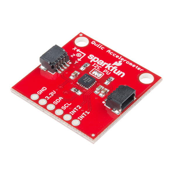
Freescale's MMA8452Q is a smart, low-power, three-axis, capacitive micro-machined accelerometer with 12 bits of resolution. It's perfect for any project that needs to sense orientation or motion. We've taken that accelerometer and stuck it on a Qwiic-Enabled breakout board, in order to make interfacing with the tiny, QFN package a bit easier. It's part of SparkFun's Qwiic system, so you won't have to do any soldering to figure out how things are oriented.
The MMA8452Q is a rock-solid, feature rich, 3-axis accelerometer. It supports three, selectable sensing ranges: ± 2g, 4g, or 8g. It also sports features like orientation detection, single and double-tap sensing, and low power modes. It's a digital sensor -- communicating over a Qwiic enabled I2C interface -- so you'll get reliable, noise-free data over a Qwiic enabled I2C port.
In this hookup guide, we'll connect our sensor up to our microcontroller of choice and read the X, Y, and Z accelerometer channels to figure out how we are accelerating in those directions. Then, we'll figure out how to use orientation detection to figure out what orientation the sensor is in.
To get started, you'll need a microcontroller to, well, control everything.
Now to get into the Qwiic ecosystem, the key will be one of the following Qwiic shields to match your preference of microcontroller:
You will also need a Qwiic cable to connect the shield to your accelerometer, choose a length that suits your needs.


If you aren't familiar with the Qwiic system, we recommend reading here for an overview.
| Qwiic Connect System |
We would also recommend taking a look at the following tutorials if you aren't familiar with them.
Let's look over a few characteristics of the MMA8452Q sensor so we know a bit more about how it behaves.
| Characteristic | Range |
|---|---|
| Operating Voltage | 1.95V - 3.6V |
| Current | 7-165 µA |
| Measurement Range | ±2g, ±4g, ±8g |
| I2C Address | 0x1D (open jumper, default) or 0x1C (closed jumper) |
The characteristics of the available pins on the MMA8452Q are outlined in the table below.
| Pin Label | Pin Function | Input/Output | Notes |
|---|---|---|---|
| 3.3V | Power Supply | Input | Should be between 1.95 - 3.6V |
| SDA | I2C Data Signal | Bi-directional | Bi-directional data line. Voltage should not exceed power supply (e.g. 3.3V). |
| SCL | I2C Clock Signal | Input | Master-controlled clock signal. Voltage should not exceed power supply (e.g. 3.3V). |
| INT2 | Interrupt 2 | Output | Programmable interrupt — can indicate data ready, orientation change, tap, and more. |
| INT1 | Interrupt 1 | Output | Programmable interrupt — can indicate data ready, orientation change, tap, and more. |
| GND | Ground | Input | 0V/common voltage. |
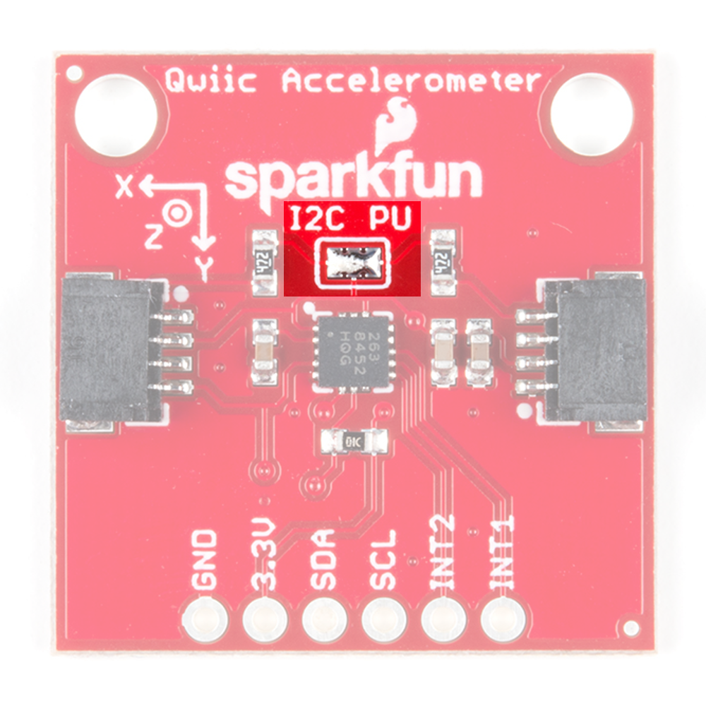
The Qwiic Accelerometer has onboard I2C pull up resistors; if multiple sensors are connected to the bus with the pull-up resistors enabled, the parallel equivalent resistance will create too strong of a pull-up for the bus to operate correctly. As a general rule of thumb, disable all but one pair of pull-up resistors if multiple devices are connected to the bus. If you need to disconnect the pull up resistors they can be removed by removing the solder on the corresponding jumpers highlighted below.
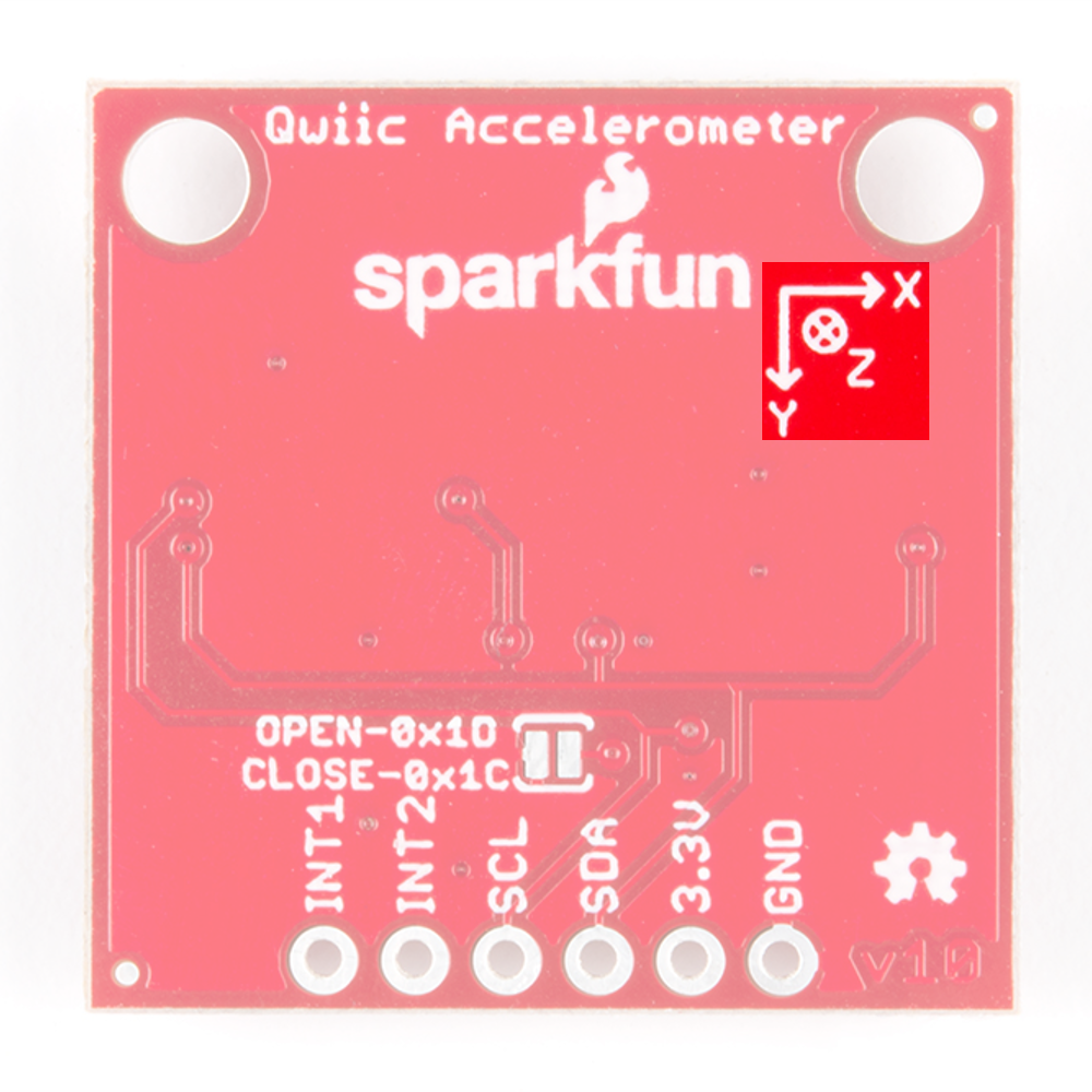
There is an additional jumper on the back of the board that allows the I2C to be changed from the default 0x1D to 0x1C if you have multiple accelerometers on the same I2C bus. However, if you have more than 2 accelerometers, you'll need the Qwiic Mux to have them all on the same I2C bus. The jumper is highlighted below. Normally open, the jumper sets the I2C address to 0x1D. Closing the jumper with solder will give an I2C address of 0x1C.
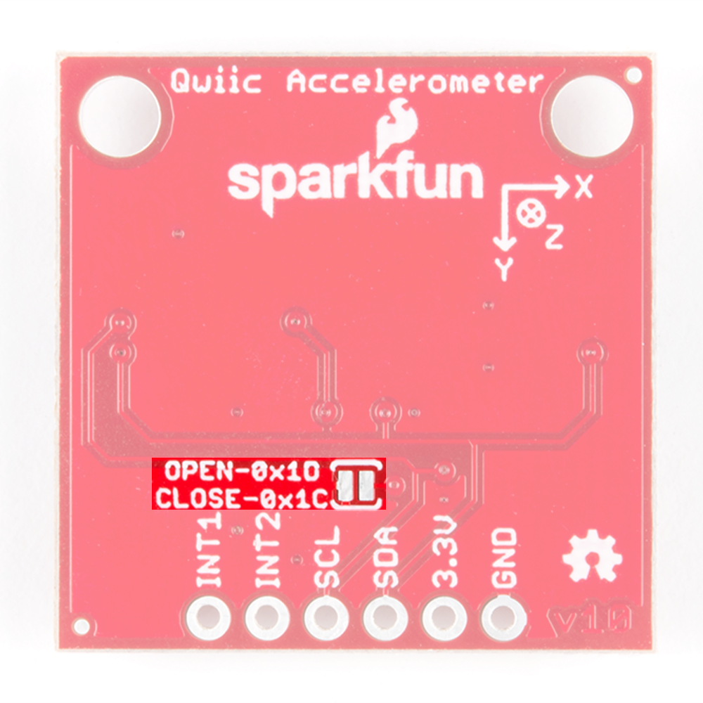
Also be sure to check out the labeling on the back of the board that indicates the orientation of the positive X, Y, and Z axes so you know what exactly your data means.
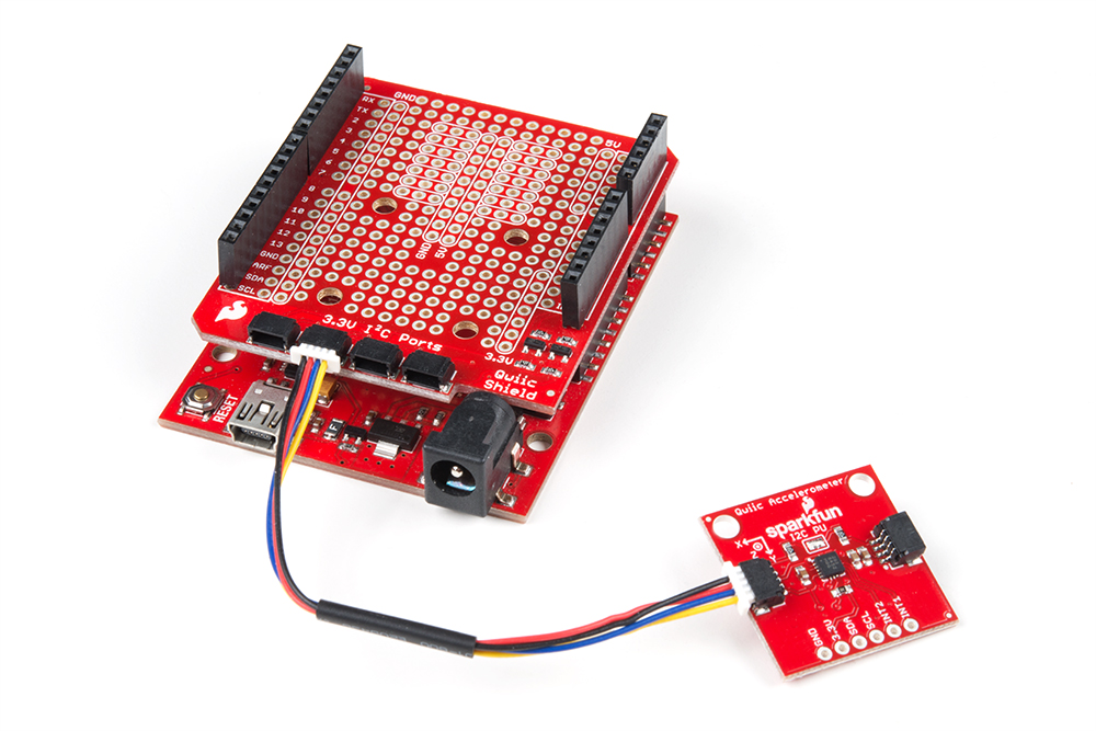
If you haven't yet assembled your Qwiic Shield, now would be the time to head on over to that tutorial. With the shield assembled, Sparkfun's new Qwiic environment means that connecting the sensor could not be easier. Just plug one end of the Qwiic cable into the Accelerometer breakout, the other into the Qwiic Shield of your choice and you'll be ready to upload a sketch and figure out how your board is moving around. It seems like it's too easy to use, but that's why we made it that way!
Note: This example assumes you are using the latest version of the Arduino IDE on your desktop. If this is your first time using Arduino, please review our tutorial on installing the Arduino IDE. If you have not previously installed an Arduino library, please check out our installation guide.
We've written an Arduino library to make interfacing with the MMA8452Q as easy as can be. Click on the button below to download the library. Or you can grab the latest, greatest version over on the library's GitHub repository.
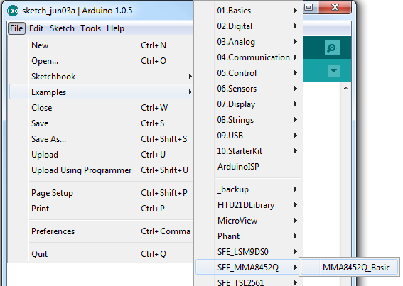
Once you've installed the SFE_MMA8452Q library, restart Arduino. Then go to File > Examples > SFE_MMA8452Q > MMA8452Q_Basic to open the example sketch.
Once you've set your Board and Serial Port, upload the sketch to your Arduino. Then open the serial monitor. You'll begin to see acceleration values stream by, in addition to some information about the sensor's orientation.
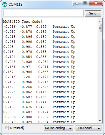
Try moving the sensor around to change those values. If it is motionless, flat on the desk, then an acceleration of 1g should be felt on the z-axis, while the others feel around 0. Test the other axes by rotating the board and making them feel the pull of gravity.
Here are some tips on using the MMA8452Q Arduino library so you can embed it into an Arduino sketch of your own.
To begin, you need to "include" the library in your sketch:
language:c
#include <Wire.h> // Must include Wire library for I2C
#include <SFE_MMA8452Q.h> // Includes the SFE_MMA8452Q library
The library also requires that you include Wire.h in your sketch. Make sure you include that before you include the SFE_MMA8452Q.h file.
Once the library is included, you can create an MMA8452Q object. This line of code will do it for you:
language:c
MMA8452Q accel; // Default MMA8452Q object create. (Address = 0x1D)
Optionally, you can define the 7-bit I2C address of your MMA8452Q in this parameter, using one of these lines of code:
language:c
MMA8452Q accel(0x1C); // Initialize the MMA8452Q with an I2C address of 0x1C (SA0=0)
MMA8452Q accel(0x1D); // Initialize the MMA8452Q with an I2C address of 0x1D (SA0=1)
But if you've left the address jumper untouched (meaning the "SA0" pin is connected to VCC), you can call the default (no parameter) constructor shown earlier.
Finally, in the setup() function of your sketch, you can initialize the accelerometer using the init() function. The init() function verifies communication with the accelerometer, and sets up the full-scale range and output data rate.
Again, you have a few options here. You can use a simple declaration like below. This will initialize the accelerometer with range of ±2g and an output data rate of 800 Hz (turns the accelerometer up to the max!):
language:c
accel.init(); // Default init: +/-2g and 800Hz ODR
If you want to specify the acceleration and output data rate, you can instead use an init() function like this:
language:c
accel.init([scale], [odr]); // Init and customize the FSR and ODR
Scale can be either SCALE_2G, SCALE_4G, or SCALE_8G. The "odr" variable can be either ODR_800, ODR_400, ODR_200, ODR_100, ODR_50, ODR_12, ODR_6, or ODR_1, respectively setting the data rate to 800, 400, 200, 100, 50, 12.5, 6.25, or 1.56 Hz.
Once you've set the accelerometer up, you can immediately start reading the data coming out of the chip. Reading and using the values is a two-step process. First, call the read() function to pull in the values.
language:c
accel.read(); // Update acceleromter data
After you've called the read() function, you can use either of two sets of values to use the data. Reading from the x, y, and z class variables will return a signed 12-bit integer read straight out of the accelerometer.
language:c
xAcceleration = accel.x; // Read in raw x-axis acceleration data
Serial.print("Acceleration on the x-axis is ");
Serial.println(xAcceleration);
Or, if you want a value with physical units, you can use the cx, cy, and cz class variables. These are the calculated acceleration values read out of the accelerometer; they'll be in units of g's.
language:c
zAcceleration = accel.cz; // Read in calculated z-axis acceleration
Serial.print("Acceleration on the z-axis is: ");
Serial.print(zAcceleration);
Serial.println(" g's");
Remember! Those variables are only updated after the read() function is called. Make sure that happens before you start using acceleration values.
The MMA8452Q has all sorts of nifty, extra features, one of which is orientation detection -- it can estimate if it's being held in landscape mode, portrait mode, or flat.
To read the portrait/landscape data from the accelerometer, use the readPL() function. This function returns a byte, which will either be equal to PORTRAIT_U, PORTRAIT_D, LANDSCAPE_R, LANDSCAPE_L, or LOCKOUT.
language:c
byte pl = accel.readPL();
switch (pl)
{
case PORTRAIT_U:
    Serial.print("Portrait Up");
    break;
case PORTRAIT_D:
    Serial.print("Portrait Down");
    break;
case LANDSCAPE_R:
    Serial.print("Landscape Right");
    break;
case LANDSCAPE_L:
    Serial.print("Landscape Left");
    break;
case LOCKOUT:
    Serial.print("Flat");
    break;
}
As in the example above, you can use if or switch statements to check which orientation your accelerometer is in.
Thanks for reading! We're excited to see what you build with the MMA8452Q. If you're left needing more MMA8452Q-related documentation, check out some of these resources:
Need some inspiration for your next project? Check out some of these related tutorials:
Or check out this blog post for ideas:
learn.sparkfun.com | CC BY-SA 3.0 | SparkFun Electronics | Niwot, Colorado