Portable DIY Teensy Synth
 Chowdah
Populate and Connect
Insert each top arcade button, optionally using the 3D-printed support inside if more rigidity is needed. Remove, then reinsert, microswitches to clear the holes. Link each button’s common pin together using wire and spade connectors, then run the final wire to ground. Link each button to its own individual lead/spade connector, and attach to the corresponding Teensy GPIO via the main board. The input is pulled low when pushed. For organization, I used black wires for each black button, white wires for each white button, and green for ground. Zip-ties are recommended to keep things organized.


Connect the speakers and 3D-printed grill with M3 bolts/nuts. Solder wires onto each speaker’s positive and ground pin to be connected to the I2S amplifier. Ensure all wires are long enough to accommodate the box lid opening and closing, and connect to the appropriate pins on the main board and amplifier via their screw terminals. For the side implements, solder leads to the potentiometer, connecting one side to ground, the other to +3.3V, and the middle to analog pin 17. This acts as a voltage divider and volume knob. Solder leads to the SPST speaker mute button, along with the LED pin if it has one. Connect the switch common and LED negative to GND (I used the screw terminal on the amplifier for GND). Connect the switch NO pin to Teensy GPIO 16 as a mute input, and LED positive to Teensy GPIO 17 to control the light.

Solder wires to VBUS and GND on the USB-C breakout, and connect these to the + and GND pins respectively to the main power switch. Connect the switch’s light icon pin to the +5V rail on the solderable breadboard, and connect the GND pin to the GND rail on the board. Connect the amplifier’s VIN and GND to the main board’s +5V and GND. Plug in the Qwiic connector to the amp and connect leads to SDA, SCL, GND, and +3.3V on the main board as outlined in the schematic. Connect the speakers to the appropriate left/right screw terminals. Connect the charge port of your USB battery pack to the USB-B to USB-A pass-through via a USB-C to USB-A cable. Connect the USB-A output from the battery pack to the switch breakout via a USB-A to USB-C cable. Depending on the battery setup, other cables may be needed/used. Run the 3.5mm signal splitter input to the Teensy Audio shield’s stereo jack. Connect one side to the speaker amp and the other to the audio pass-through using the two 3.5mm stereo cables.
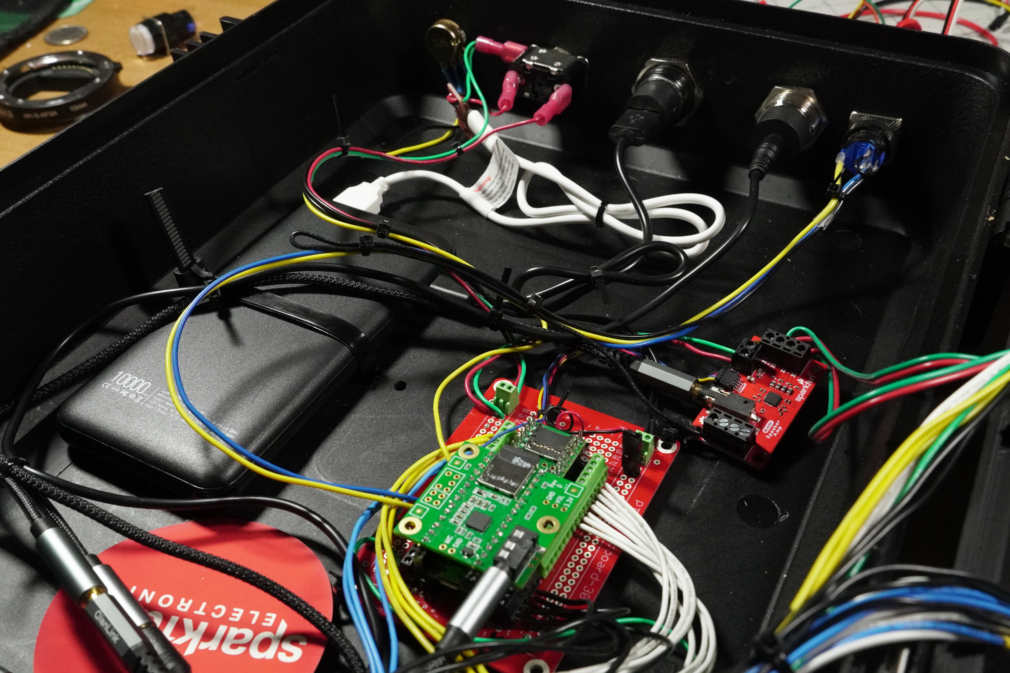

Once you’re satisfied that connections are in place and that the box can open and close without issue, drill holes in the bottom of the box and feed zip-ties through to strap down the main board, amplifier, and battery pack. Use more zip-ties to straighten out the wiring as expedient.