PCA9306 Logic Level Translator Hookup Guide (v2)
 Toni_K,
  bboyho
Hardware Assembly
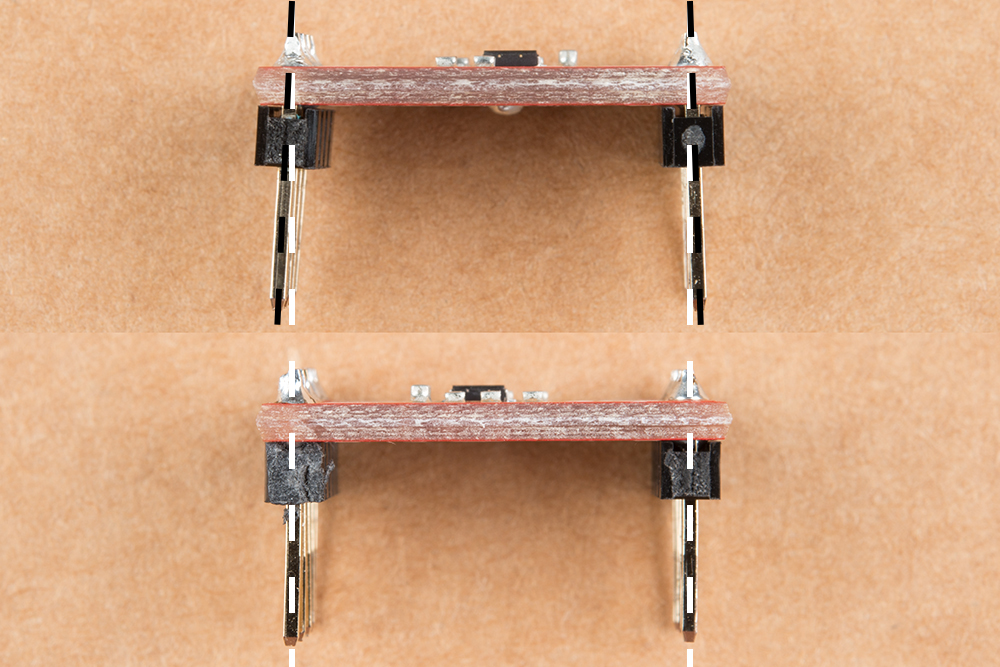
To connect the board, you will need to solder headers into the through-holes, and use jumper wires to connect between devices when prototyping. Make sure to place it on a breadboard before soldering to test. You will need to make sure that the headers on each side of the PCA9306 breakout board are soldered at an angle in order for it to sit securely on a breadboard. The board shown at the top of the image shows how the pins are offset and soldered at a small angle. The board shown at the bottom of the image shows pins flush with the board. You will want to make sure that you soldered the pins like the board shown at the top of the image.
You could also just solder some hookup wire or add a protoshield to connect all of your boards together securely for a project.