$59.95
The SparkFun OpenLog Artemis (OLA) is a versatile, open source data logger that comes preprogrammed to automatically log a wide variety of data from a large number of sensors. And here’s the best bit… You can do all of this without writing a single line of code! The OLA automatically detects which sensors are connected to it and logs the data to microSD card in standard Comma Separated Value (CSV) format. The OLA is designed for users who just need to capture a bunch of data and get back to their larger project. We will quickly get you up to speed with the OLA and the Qwiic ecosystem so you can start logging all that data!
To follow along with this tutorial, you will need the following materials. You may not need everything though depending on what you have. Add it to your cart, read through the guide, and adjust the cart as necessary.
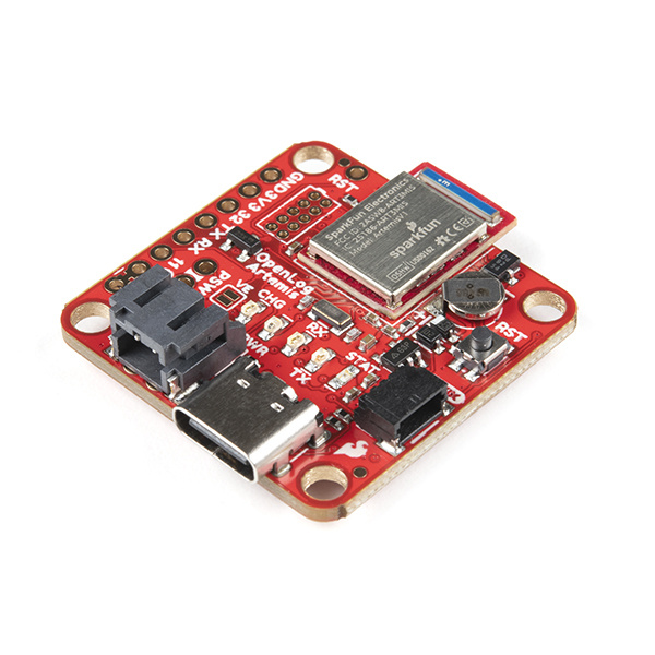
Straight out of the box anti-static bag the OLA [DEV-16832] is ready to log data from its built-in ICM-20948 Inertial Measurement Unit (IMU) 9-Degrees-Of-Freedom (9-DOF) sensor. Only want to log magnetometer, accelerometer, gyro or temperature data? You’re good to go! But the fun is only just beginning…
The OLA is preprogrammed to automatically log data from all of the following sensors, so you may wish to add one or more of these to your shopping cart too. (More sensors are being added all the time and it is really easy to upgrade the OLA to support them. But we’ll get to that in a moment!)
If you aren't familiar with the Qwiic system, we recommend reading here for an overview.
| Qwiic Connect System |
We also recommend checking out these tutorials before continuing.
The Artemis module is the world's first open source hardware RF processor module. A surprising amount of power can be packed into 10x15mm! Based around the Apollo 3 ARM Cortex-M4F from Ambiq Micro, it runs at 48MHz but with low power consumption. It comes with Bluetooth Low Energy (BLE) wireless communication built-in and we plan to upgrade the OLA to support wireless sensing in the coming months. (Don’t forget: it is really easy to upgrade the OLA firmware. But we’ll get to that in a moment!).
Ambiq, the manufacturer of the Apollo3, has done years of research into something they call Sub-threshold Power Optimized Technology (SPOT™). This is a fancy description of a power saving technique that works by lowering the logic level voltages necessary to indicate a 1 or a 0. By doing so at the silicon level, Ambiq has managed to eke out a 48MHz processor which can draw less than half a milliamp.
The Artemis has a built-in Bluetooth 5.0 radio capable of transmitting up to 4dBm which should get you about 70m transmission distance. We’ve seen successful RSSI checks at over 200ft.
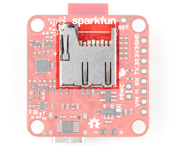
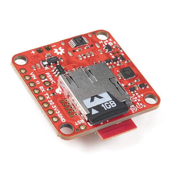
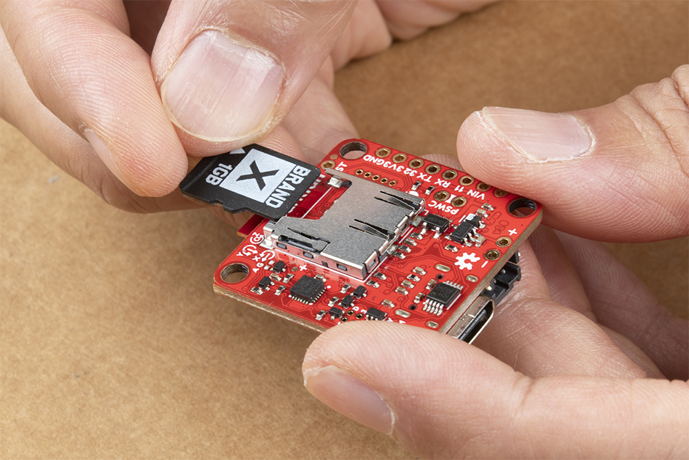
OpenLog uses common microSD cards to record clear text, comma separated files. Flip over the OLA and you’ll see the latching microSD card socket. You probably already have a microSD card laying around but if you need any additional units, we have plenty in the store. The OLA can use any size microSD card and, as of firmware version 1.11, supports exFAT cards in addition to FAT32. Please ensure your SD card is formatted correctly; we recommend the SD Association Formatter.
Slide in your formatted SD card and it will click neatly into place. The edge of the SD card will line up with the edge of the circuit board when it is inserted correctly.
As of firmware v1.6, the log file metadata (create and access timestamps) are now set correctly using the OLA’s Real Time Clock. The files on the SD card can also be accessed via the USB terminal interface. A new configuration menu allows you to:
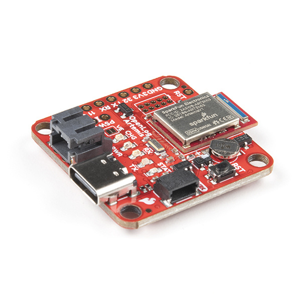
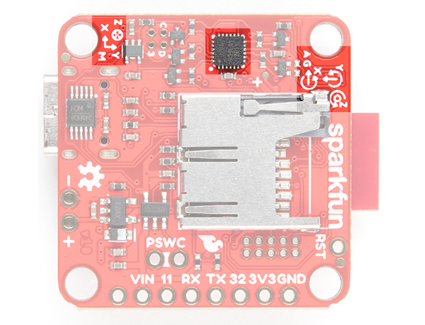
Included on every OpenLog Artemis [DEV-16832] is an Inertial Measurement Unit (IMU) for built-in logging of triple-axis accelerometer, gyro and magnetometer data. Whereas the original 9DOF Razor used the old MPU-9250, the OpenLog Artemis uses the latest ICM-20948 capable of nearly 250Hz logging of all 9 axes. Oh, and if that wasn’t enough, it comes with a built-in temperature sensor too. So if you want to use the OLA as a transportation logger, it will do that straight out of the anti-static bag! On every OpenLog Artemis without IMU [DEV-19426], the ICM-20948 IMU sensor and associated circuitry is removed. Users using the OpenLog Artemis without IMU will not be able to log sensor data or configure the ICM-20948 if the sensor is not detected.
 |
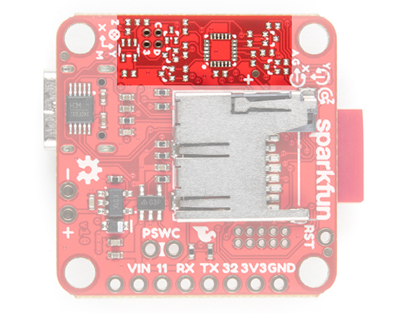 |
| With IMU [DEV-16832] | Without IMU [DEV-19426] |
There are a variety of power and power-related nets broken out to connectors and through hole pads. Below list a few methods of powering the board up. The voltage is regulated down to 3.3V with the AP2112K for the system voltage.
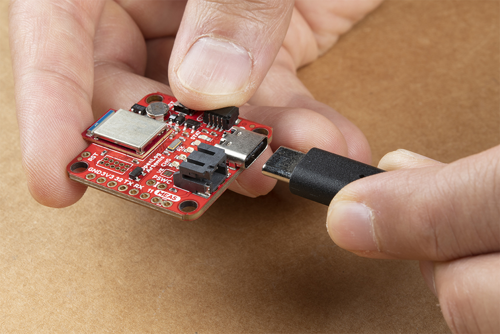
Micro-USB is just so passé. Like all recent SparkFun boards, the OLA comes equipped with a USB-C socket which you can use to:
USB-C power supplies are clever beasties and the OLA includes the configuration channel resistors needed to tell the power supply to deliver 5V. So, yes, you can use your USB-C laptop charger as the power source should you need to, even though it normally delivers a much higher voltage. This can also be used to charge the LiPo battery at a default rate of 450mA or program the board.
For customers in North America, our NEMA Raspberry Pi Wall Adapter is a perfect choice. You can also power the OLA from our Lithium Ion Battery Pack - 10Ah (3A/1A USB Ports) but you will need a USB-C cable too:
But of course you’re going to want to use the OLA to log sensor data while on the move too. You can connect one of our standard single cell LiPo batteries to the OLA and power it for hours, days or weeks depending on what sensors you have attached and how often you log data. The OLA has a built-in charger too which will charge your battery at 450mA when USB-C is connected. Please make sure your battery capacity is at least 450mAh (0.45Ah); bad things will happen if you try to charge our smallest batteries at 450mA. Underneath the JST connector the pins are broken out if you decide to solder a single cell LiPo battery directly to the board.
 |
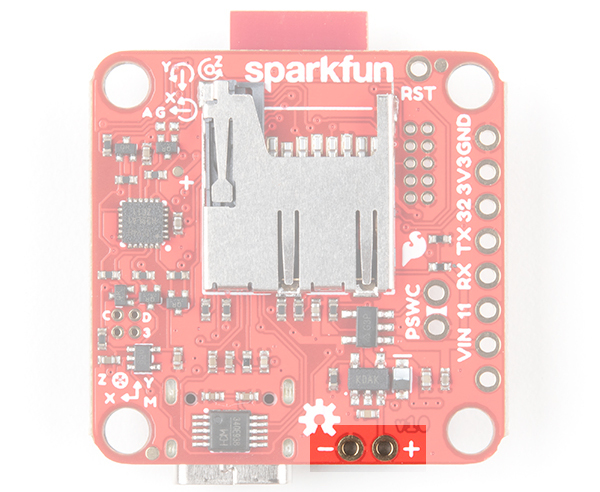 |
| JST Connector for Single Cell LiPo Battery | VBATT and GND Pins |
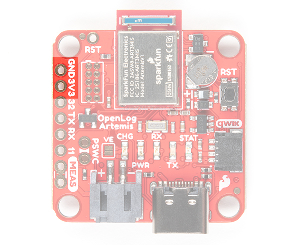
For those going the old school route, you can also solder directly to the 3V3 and GND pin to provide power if your application has regulated 3.3V.
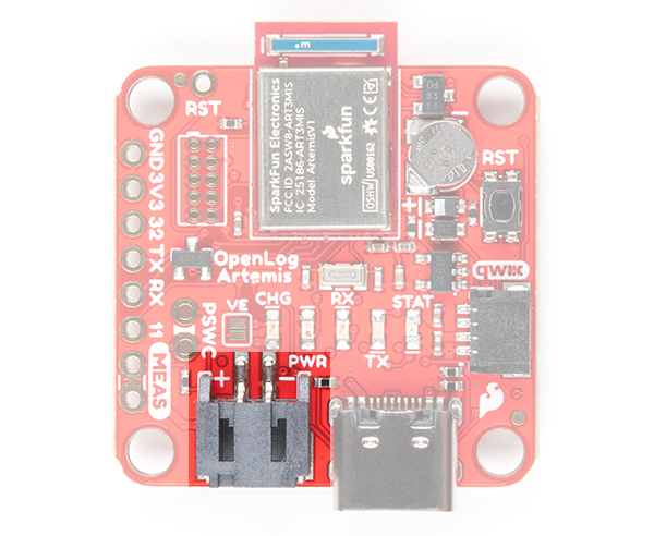
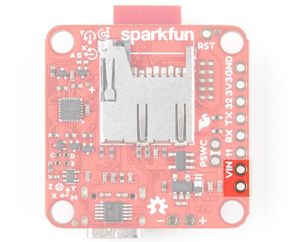
On the back of the board, you will notice that there is a pin labeled VIN. We don’t recommend it, but you can also feed in external power (recommended operating voltage of 6.0V Maximum) via the VIN pin next to breakout pin 11. We don’t recommend it because there is no protection diode between this pin and USB-C 5V power. If you have VIN and USB-C connected at the same time, bad things could happen. If VIN is your only option then we recommend cutting the MEAS jumper to isolate VIN from USB 5V and the LiPo.
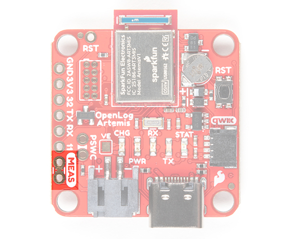 |
 |
| MEAS Pin | MEAS Pins connected to VIN and 5V USB pin |
On the other side of the USB-C connector is a CH340 USB-to-Serial Converter. The chip can be used to send serial data to your computer or upload new firmware with the Artemis Firmware Uploader.
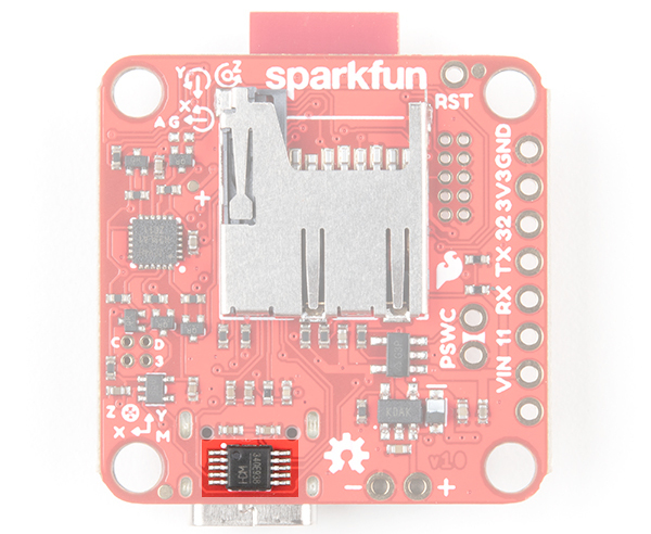
The driver should automatically install on most operating systems. However, there is a wide range of operating systems out there. You may need to install drivers the first time you connect the chip to your computer's USB port or when there are operating system updates. For more information, check out our How to Install CH340 Drivers Tutorial.
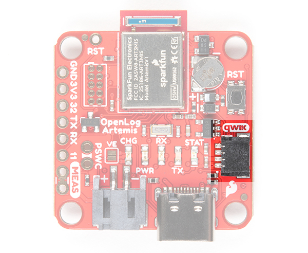
SparkFun's Qwiic Connect System uses 4-pin JST connectors to quickly interface development boards with I2C sensors and more. No soldering required and there's no need to worry about accidentally swapping the SDA and SCL wires. The Qwiic connector is polarized so you know you’ll have it wired correctly every time, right from the start. Qwiic boards are daisy chain-able too so you can connect multiple sensors to the OLA and log readings from all of them.
Sometimes you might want to connect more than one of the same type of sensor to the OLA. On the I2C bus, each device needs to have a unique address. On many of our boards, there are jumpers links which you can use to change the address and some have addresses that can be configured in software. But there are some where you cannot change the address. The solution is to use one of our Qwiic Mux Breakouts which will allow you to connect multiple devices with the same address to the OLA.
The OLA includes a dedicated 3.3V regulator for the Qwiic connector. This has several advantages including:
The I2C pins are also broken out on small PTH pins on the back of the board. Keep in mind that these are not standard breadboard sized PTH pins so you will need some thin wires to connect.
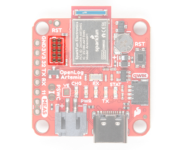
In addition to logging IMU and sensor data, OpenLog Artemis can also log serial streams and analog voltages! You will find the breakout pins along the edge of the board:
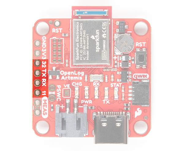
Analog voltages are converted and logged in much the same way as the other sensor values are. Each analog channel can be enabled or disabled. The values can be either a raw ADC reading (0 to 16,383) or a floating point value (0 to 2.0V)
Serial communication is 3.3V. You will need an adapter if you need to log old-school RS232 data which uses higher voltages.
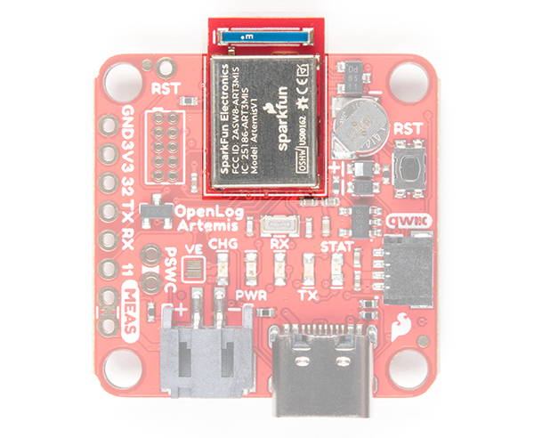
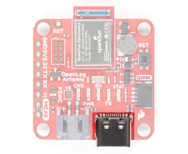
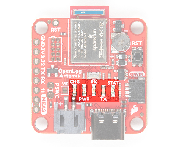
There are 5x LEDs on the board:
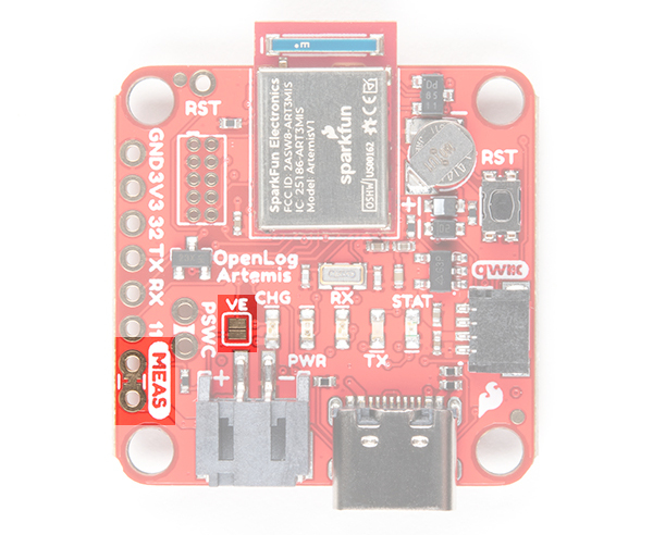
There are two jumpers on board:
 |
|
| VE and MEAS Jumpers | MEAS Pins connected to VIN and 5V USB pin |
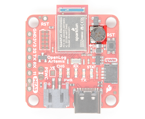
The Artemis has a built-in Real Time Clock (RTC) which is used to timestamp the logged data. You can set the clock time and date and enable timestamping through the configuration menus. If you have one of our u-blox GNSS modules attached, you can use that to set the RTC. We have included timezone adjustment too!
The OLA has an onboard 1mAh backup battery which is designed to keep the RTC running when the external power is removed. The battery requires 20 minute to charge. The OLA will require a reset to bring it back out of deep sleep when the power is reconnected. See “Low Power Considerations” for further details.
Pressing the miniature reset button, as you might expect, will reset the Artemis. If you have your OLA mounted in an enclosure, you can also attach an external reset switch too. Any Single Pole Normally-Open Push-To-Close momentary switch will do. Solder pin headers or wires to the RST and GND breakout pins and connect your external switch to those.
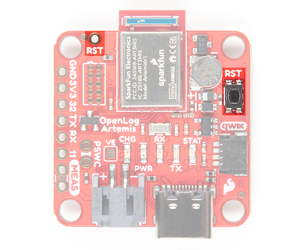
Pressing the reset button will cause the Artemis to restart the firmware. If the OLA was in deep sleep, pressing the reset button will wake it. See “Low Power Considerations” for further details.
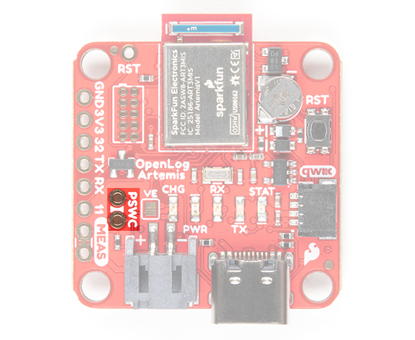
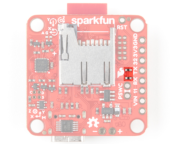
The Power Switch (aka PSWC) header can be used to attach an external switch. If you need power control on the outside of an enclosure, solder header pins or wires to the PSWC breakout pins and attach your switch to those. Any Single Pole Single Throw (SPST) toggle switch will do.
When the PSWC header is shorted together by the switch, the enable pin of the 3.3V regulator is pulled low, turning off the power to the OLA. The Artemis will go into deep sleep and draw approximately 18µA of standby current from the RTC battery. The OLA will require a reset to bring it back out of deep sleep when the power is turned back on. See “Low Power Considerations” for further details.
The OLA has two ways to measure the incoming power voltage. A two-resistor divider allows the Artemis to monitor the power (battery) voltage via one of its analog pins. The OLA code keeps an eye on the battery voltage and will stop logging and put the Artemis into deep sleep when the battery voltage becomes too low. As of firmware v1.6, you can now adjust the low battery threshold voltage via the menus.
The OLA also includes a 3.0V supervisory circuit. If the external power is disconnected or switched off, the supervisor causes an interrupt which forces the Artemis into immediate deep sleep.
While the Artemis is in deep sleep, the back-up battery will keep the RTC running. When power is restored, the OLA will require a reset to bring it back out of deep sleep. See “Low Power Considerations” for further details.
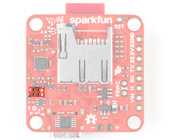
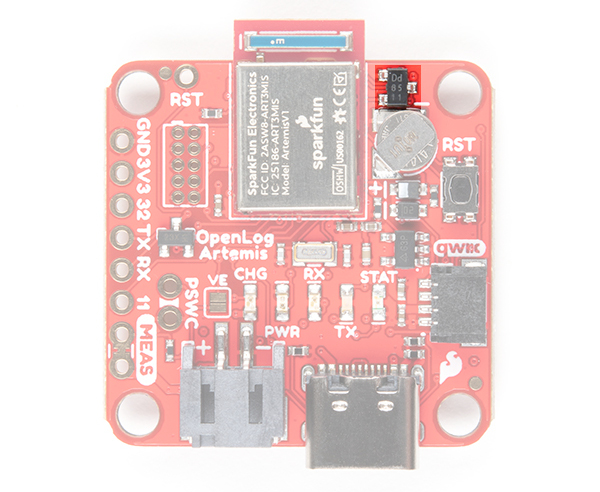
The single wire debug port is available for advanced users who need low-level debugging tools.
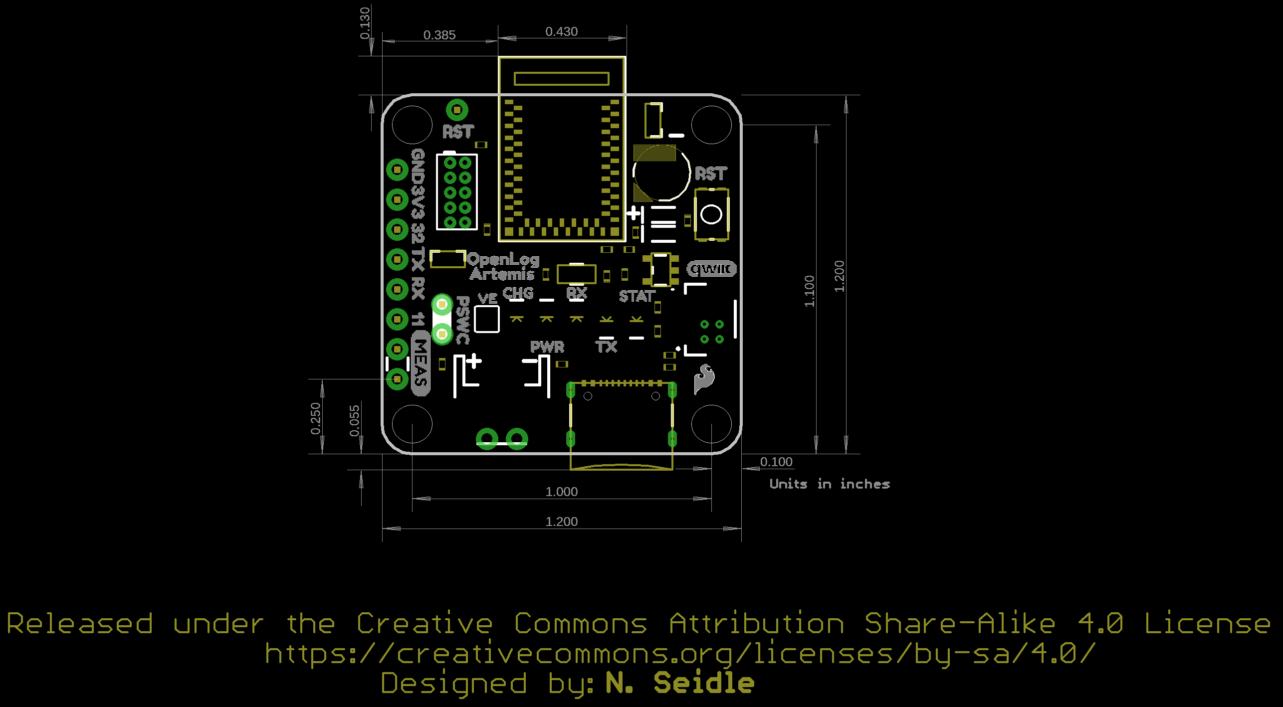
The board has four mounting holes. The overall size of the board (including the USB C connector and Artemis module hanging over the edge of the board) is about 1.20"x1.43".
If all you want to do is display your sensor readings in a serial terminal or monitor (connected via USB-C) then, strictly, you don’t need to add a microSD card. But of course the whole point of the OLA is that it can log readings from whatever sensors you have attached to microSD card. The data is logged in easy-to-read Comma Separated Value (CSV) text format.
You probably already have a microSD card laying around but if you need any additional units, we have plenty in the store. The OLA can use any size microSD card and, as of firmware version 1.11, supports exFAT cards in addition to FAT32. Please ensure your SD card is formatted correctly; we recommend the SD Association Formatter. Flip over the OLA and you’ll see the latching microSD card socket. Slide in your formatted SD card and it will click neatly into place. The edge of the SD card will line up with the edge of the circuit board when it is inserted correctly.
You should only insert or remove the SD card while the power is turned off or disconnected. Removing the card while the OLA is logging will almost certainly corrupt your data.
After you’ve logged some data, you will find several new files on your SD card:
If you are going to attach extra sensors to the OLA, then those need to be connected first before attaching a USB cable. It is a good idea to only attach or disconnect Qwiic sensors when the power is turned off or disconnected. The Qwiic bus is pretty tolerant to “hot swapping”, but: disconnecting a sensor while it is in use will confuse the OLA software; and a new sensor won’t be detected until the firmware restarts.
Plug one end of your Qwiic cable into the OLA and plug the other end into your sensor. If you want to add extra sensors, you can simply connect them to each other in a daisy chain. You will need a Qwiic cable for each sensor. Our Qwiic Cable Kit covers all the options
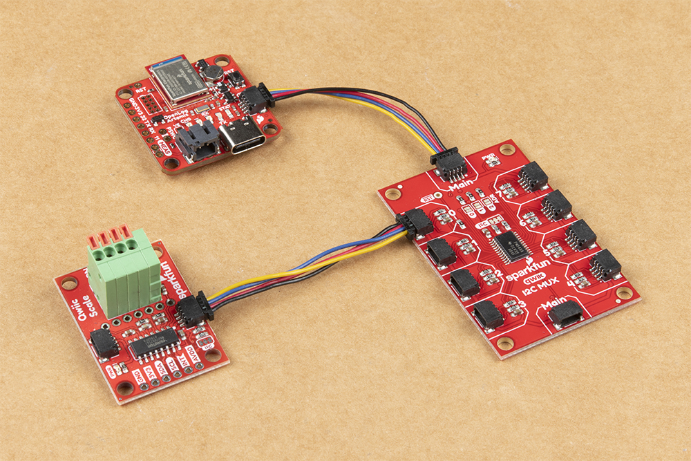 |
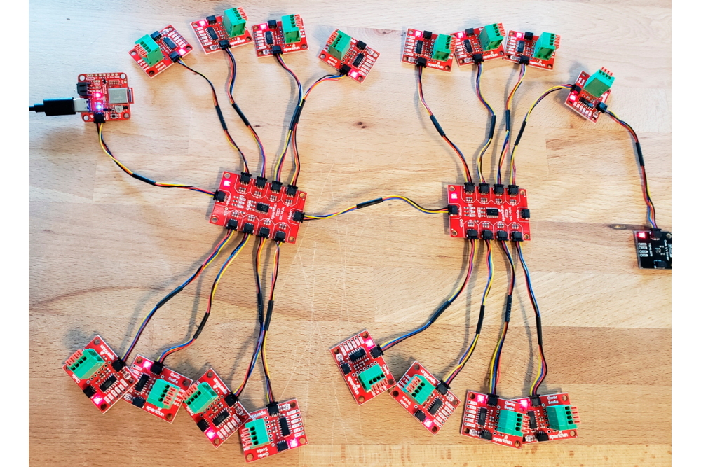 |
| OLA and a Qwiic Sensor/Mux | OLA and several Qwiic Enabled Devices |
Our Qwiic sensors usually all have power indicator LEDs and I2C pull-up resistors. Depending on your application, you may want or need to disable these by cutting the jumper links on the sensor circuit boards. We have a tutorial that will show you how to do that safely.
Sometimes you might want to connect more than one of the same type of sensor to the OLA. On the I2C bus, each device needs to have a unique address. On many of our boards, there are jumpers links which you can use to change the address and some have addresses that can be configured in software. But there are some where you cannot change the address - the NAU7802 Qwiic Scale being one example. The solution is to use one or more of our Qwiic Mux Breakouts to allow you to connect multiple devices with the same address to the OLA.
If you want to log biometric data from the MAX30101 Pulse Oximeter and Heart Rate Sensor, you will need to:
We have headers and jumper wires in the store which will help here.
The USB-C connector provides power to the OLA and acts as a serial interface for configuration and data display.
If you are going to use a microSD card to store your data, and why wouldn’t you, then insert that first before attaching your USB cable. You should only insert or remove the SD card while the power is turned off or disconnected. Removing the card while the OLA is logging will almost certainly corrupt your data.
Likewise, it is a good idea to only attach or disconnect Qwiic sensors when the power is turned off or disconnected. The Qwiic bus is pretty tolerant to “hot swapping”, but: disconnecting a sensor while it is in use will confuse the OLA software; and a new sensor won’t be detected until the firmware restarts.
Depending on what ports your computer has available, you will need one of the following cables:
Use the cable to connect your OLA to your computer and you will see the LEDs light as the OLA starts up. The red PWR power LED will come on. The blue STAT status LED will come on too for a second or two while the OLA configures itself. It will flash while data is being logged to SD card. The yellow and green TX and RX LEDs will flash whenever there is serial traffic on the USB interface. If you have jumped the gun and have a LiPo battery already connected, the yellow CHG charging LED may light up too.
If the STAT LED does not light up, your OLA is probably in deep sleep following a previous logging session. Pressing the RST reset button will wake it. See “Low Power Considerations” for further details.
You’ll find full instructions on how to configure the OLA in the next section.
Now is a good time to attach a LiPo battery, if you want the OLA to keep logging when you disconnect USB-C.
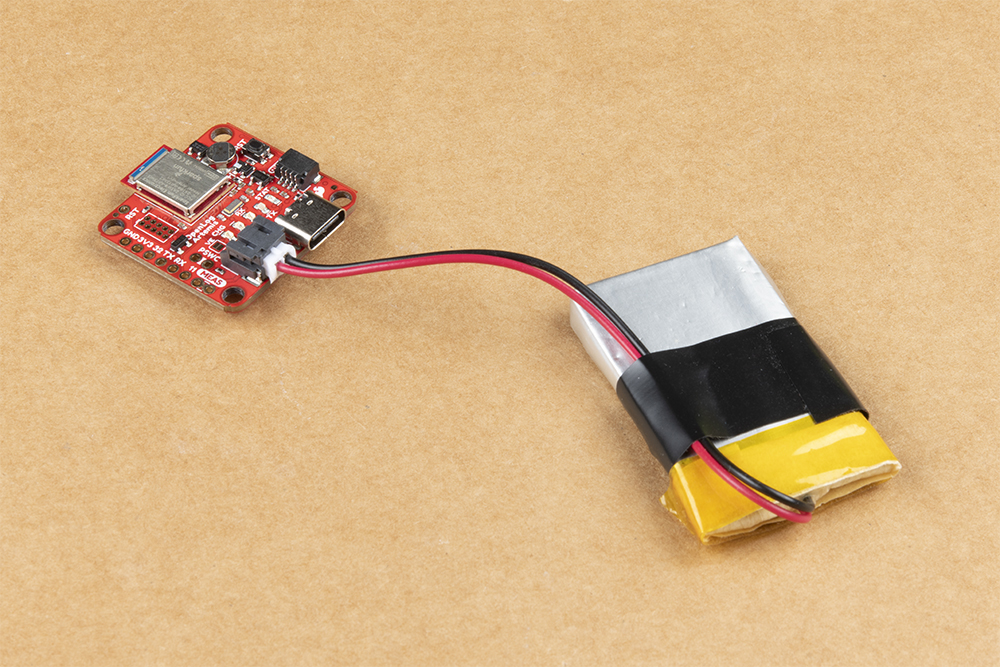
You can connect one of our standard single cell LiPo batteries to the OLA and power it for hours, days or weeks depending on what sensors you have attached and how often you log data. The OLA has a built-in charger too which will charge your battery at 450mA when USB-C is connected. Please make sure your battery capacity is at least 450mAh (0.45Ah); bad things will happen if you try to charge our smallest batteries at 450mA. The yellow CHG charging LED will light up while the battery is charging and will go out once charging is complete.
Please note that if you configure your OLA via USB-C and then disconnect the USB cable before attaching your battery, the OLA will go into deep sleep and will need a reset to wake it. You can prevent this by connecting the battery before removing your USB cable.
Serial communication has been around since 1960. Original protocols like RS232 used much higher voltages to carry data over long cables. Serial data is of course still in use today but, like many Arduino boards, the OLA only supports 3.3V serial communication. Please see our tutorial for full details.
If you feed serial data onto the RX breakout pin, the OLA will automatically log it to a separate file on the SD card. This can be useful if you want to log e.g. serial data from a GNSS module. You will need to set the serial baud rate (speed) to the correct value using the configuration menus. Please see the next section for full details.
Configuring the settings is as easy as opening a serial menu. You can use any serial monitor or terminal emulator to quickly and easily change and store the OLA settings via its USB-C interface.
If you are familiar with the Arduino IDE, you can open the Serial Monitor to configure the OLA.
If you don’t have the Arduino IDE installed, Don’t Panic!, there are plenty of free alternatives out there:
The above guides will show you how to open the correct port for the OLA and how to set the baud rate to 115200 baud. If you are using the Arduino IDE, set the line ending to Newline. You can change the OLA’s baud rate through the configuration menus too should you need to.
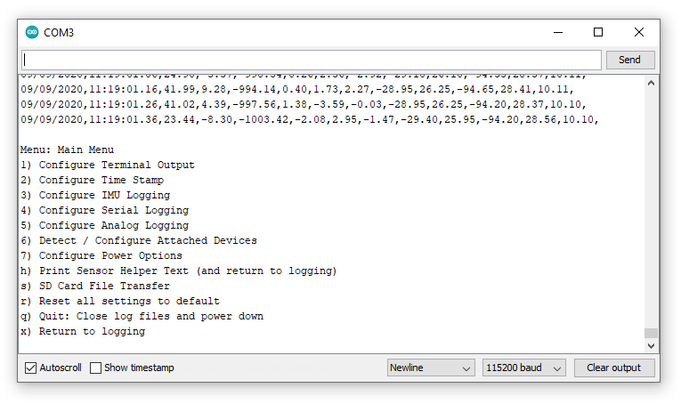
If you have been following along with the tutorial and have inserted a blank microSD card into your OLA and then connected via USB-C, when you open the serial terminal you should see:

The messages in the serial terminal tell us:
The columns of data scrolling up the screen are: RTC date, RTC time, IMU accelerometer readings (milli-g), IMU gyro readings, IMU magnetometer readings (nT), IMU temperature (C), the logging rate (Hz).
The logging rate defaults to 10Hz, so as the data scrolls past, you will see the last value settle at 10.00Hz.
Right! Let’s open the main menu by: clicking “Send” if you are using the Arduino IDE; or pressing any key if you are using one of the other serial terminal programs.
The menus will timeout after 15 seconds of inactivity, so if you do not press a key the OLA will return to data logging after 15 seconds.
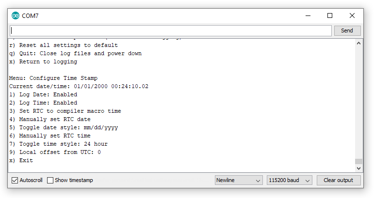
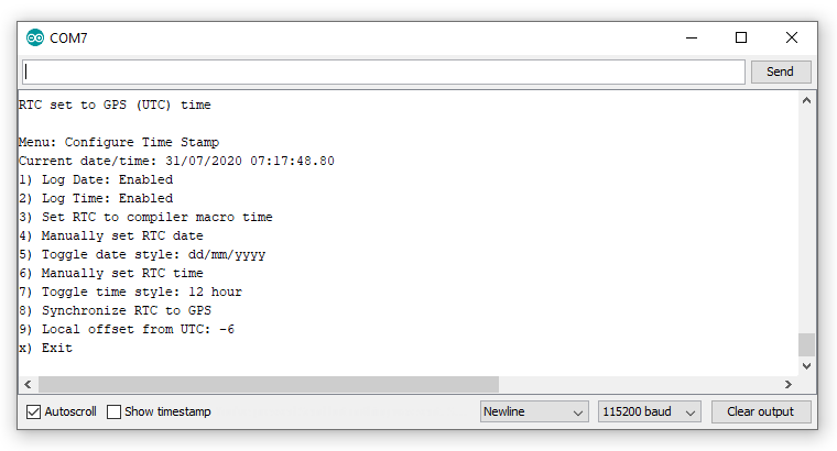
Let’s start by setting the Real Time Clock (RTC). If you are using the Arduino IDE. enter 2 in the text box at the top of the window and click Send or press the Enter key on your keyboard. If you are using another serial monitor, type 2 followed by Enter. The Time Stamp menu will be displayed:
Let’s use option 4 to set the RTC date. Type 4 followed by Send or Enter. The menu asks us for the two digit year, followed by the month and day:
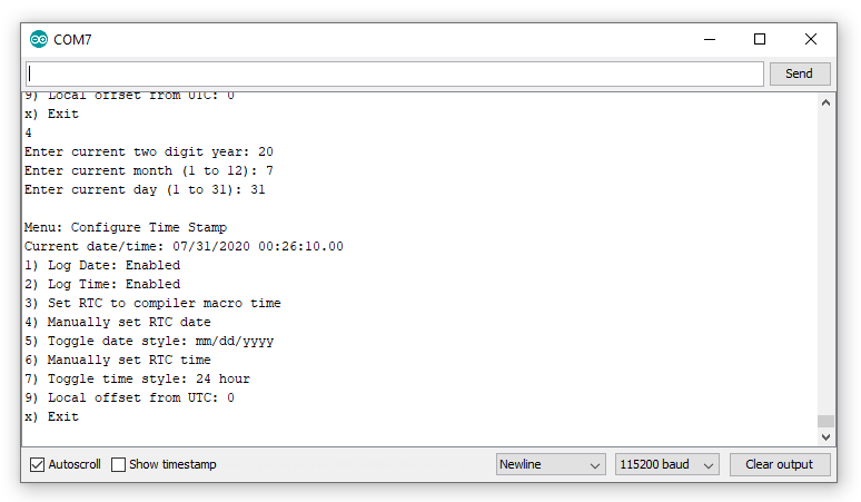
The menu now shows that we have set the date and that the MM/DD/YYYY style is being used. We can swap to DD/MM/YYYY by using option 5:
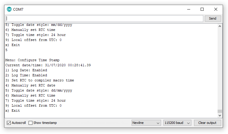
Now we can use option 6 to set the time:
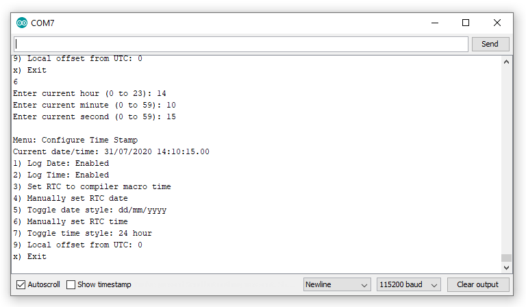
We need to enter the hour in 24 hour format even if 12 hour format has been selected (using option 7).
To set the clock accurately, you can enter a value for the seconds that is a few seconds ahead of time and then hit Enter or click Send when your watch reaches that second.
If you have a u-blox Global Navigation Satellite System (GNSS) module attached, you will see an extra option “8” which allows you to set the time to Universal Time Coordinate (UTC) using GNSS. You can use option 9 to set your local time offset. Do this before you use option 8. E.g. if you are in Colorado and daylight saving is in effect, enter -6 as the offset. Mountain Time is 6 hours behind UTC in summer.
Options 1 and 2 can be used to stop the OLA from logging the time and date should you want to.
Press x followed by Enter or Send to return to the main menu, or wait 15 seconds for the menu to timeout.
The RTC back-up battery will keep the RTC running while the OLA is in deep sleep. (Don’t forget: pressing the RST button with no power source connected will cause the RTC to reset.)
There are some other important options on the menu menu that we should cover, before we move on to the other menus:
Use option h to print the log data helper text (and return to logging) if you need a reminder of what each column of data is.
As of firmware v1.6, option s will open the SD Card File Transfer menu. See “SD Card File Transfer” for more details.
Option r followed by y will reset all of the OLA’s settings back to the default both in EEPROM and on SD card.
Option q followed by y is a clean way to stop the OLA from logging. The OLA will close the log files on the SD card, making sure the contents are saved, and will then go into deep sleep to minimize current draw. Once in deep sleep, the Artemis needs to be reset to wake it up again. You can do this by:
Option x will exit the menu and the OLA will return to data logging.
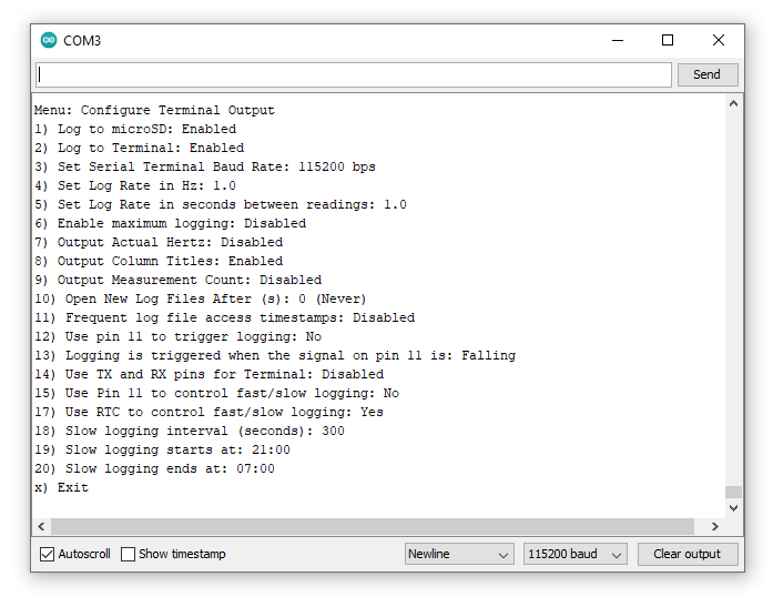
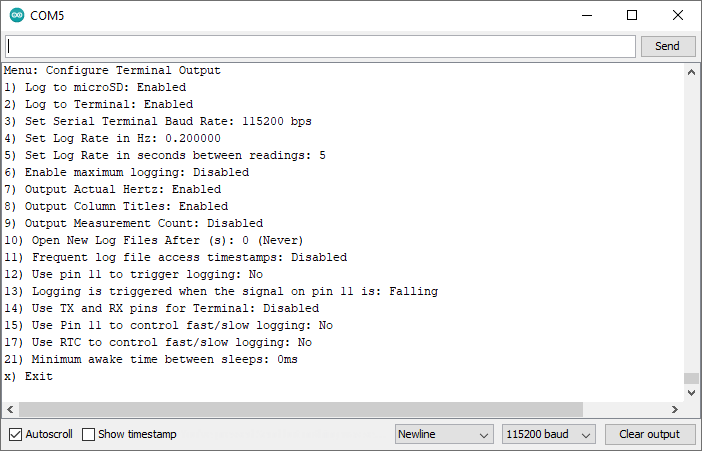
Option 1 from the main menu will open the menu to configure the terminal output:
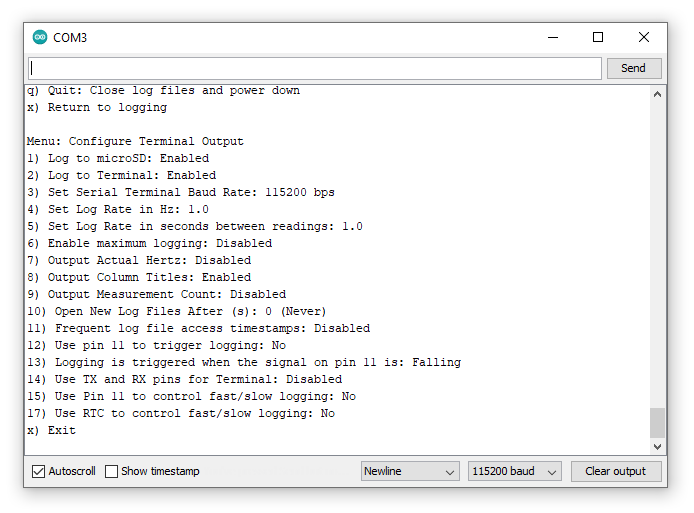
Option 1 can be used to enable or disable microSD card logging. If you are not logging to SD card, data can still be displayed on the terminal as normal.
Option 2 can be used to disable data display in the terminal. Setting “Log to Terminal” to “Disabled” stops the data from being displayed in the terminal, but it will still be logged to SD card if “Log to microSD” is enabled.
Option 3 can be used to change the baud rate used by the terminal. You will need to close and reopen the serial monitor / terminal at the new baud rate if you change this. Note: serial RX and TX pins have their own baud rate - set via main menu option 4: “Configure Serial Logging”.
Options 4 and 5 can be used to set the log rate. The log rate defaults to 10Hz. If you want to log quickly, use option 4 to set the log rate in Hz (samples per second). For slow logging, more than 1 second between samples, use option 5. The log rate sets the maximum rate for data logging, the actual log rate may be slower than this depending on what sensors are connected.
Option 6 tells the OLA to log data as fast as possible. The maximum rate depends on the number of sensors connected to the OLA.
Option 7 can be used to enable or disable logging of the actual logging rate. If you’re trying to be economical with your data, then you may wish to disable this, however leaving it enabled is a useful way to tell what logging rate was achieved.
Option 8 can be used to prevent the data column helper text from being written to the log files. If you want the log file to contain purely data, you may wish to disable this option.
Option 9 can be used to add a measurement count to each data sample. The measurement count is incremented after each sample.
Option 10 can be used to make the OLA open a new log file after the specified number of seconds. There is a small risk of data loss if the OLA’s power is removed while data is being written to the SD card. By telling the OLA to open a new log file say every hour (3600 seconds) then the most data you can lose is the past hour. (Connecting a stop logging button can prevent data loss too. See “Low Power Considerations” for further details.)
As of firmware v1.6, the following options are available:
Option 11 can be used to enable frequent log file timestamps. As of firmware v1.6, the log file create and access timestamps (metadata) are correctly set by the OLA’s Real Time Clock. By default, the access timestamps are only updated when the log files are closed. You can use option 11 to make the OLA update the timestamps frequently. However, doing so causes more SD card writes which can cause problems when logging at high rates. We made this option configurable so you can decide which is best for your application.
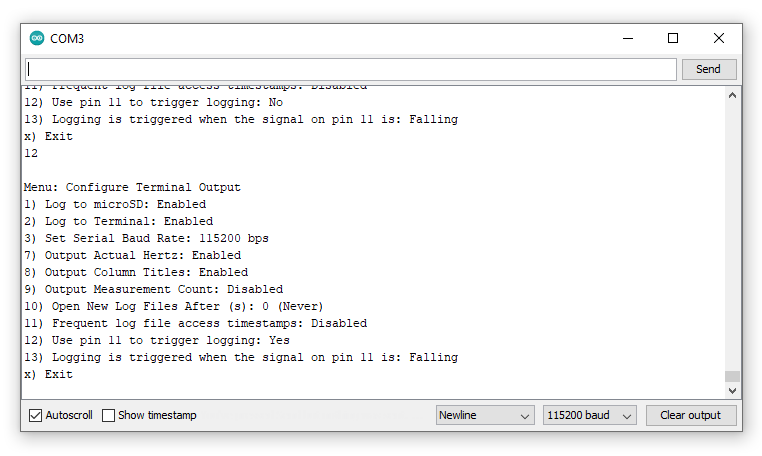
Option 12 allows pin 11 to be used to trigger sensor logging. When triggering is enabled, the sensor data is logged on every rising or falling edge on pin 11 (configurable via option 13). The normal log rate settings (options 4-6) are ignored while triggering is enabled and disappear from the menu:
As of firmware 1.9, you can use option 14 to use the TX and RX pins for the serial terminal / console. This option will allow you to attach a Bluetooth or radio modem to the OLA and access your data that way, instead of needing to use USB. You can change the Baud rate using option 3. You can still use USB when this option is enabled - you can use USB and TX/RX simultaneously. It is fun to have the TX/RX and USB serial monitor windows open at the same time, watching them both do the same thing as you type into one or the other! ZMODEM file transfer via TX/RX is supported too. Selecting this option will of course disable analog logging on the TX/RX pins and will disable serial logging too.
As of firmware 1.9, you can use option 15 to make Pin 11 control when the OLA goes into slow logging mode. Slow logging will help conserve your battery life. Let's say you only want to log during daylight hours. You could connect a 3.3V daylight sensor signal to Pin 11 so you only log at normal speed during the day and slowly at night. You can set the polarity of Pin 11 using option 16. You can set the slow rate for night using option 18.
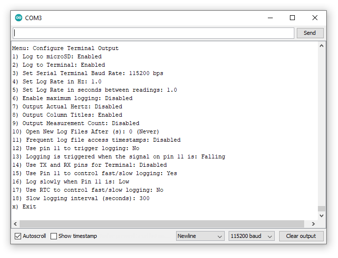
As of firmware 1.9, you can use option 17 to go into slow logging mode once per day. Again, let's suppose you want to log at normal speed during the day and then log slowly during the night. Option 17 let's you do that. You can use options 19 and 20 to set the times when slow logging should start and end.
As of firmware v1.11, you can now specify a minimum awake time for those occasions when the logging interval is greater than two seconds and the OLA goes into deep sleep between measurements. Previously it was difficult to re-open the serial menus, you had to keep hitting a key at the right moment to open the menu and stop the OLA from going back to sleep. You can now use option 21 to set a minimum awake time, in milliseconds. The OLA will wake from deep sleep, take a measurement, log it to the microSD card, optionally transmit it via the TX pin, and then remain awake for the required time, giving you time to open the serial menu. Leave this option set to zero if you want the OLA to go immediately back to sleep.
Option 3 from the main menu will open the menu to configure Inertial Measurement Unit logging:
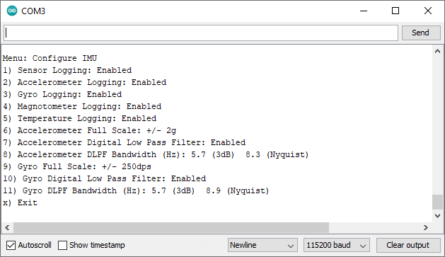
If you want to disable IMU logging completely, you can do this using option 1 to set sensor logging to disabled.
Options 2, 3, 4 and 5 can be used to selectively enable or disable logging of the accelerometer, gyro, magnetometer and temperature readings. If you just want to log temperature, use 2, 3 and 4 to disable the other readings.
As of firmware v1.7, you can use options 6 to 11 to configure the accelerometer and gyro full scale values, enable/disable the Digital Low Pass Filters, and define the DLPF bandwidths.
As of firmware v1.11, you can now optionally log quaternion orientation data using the ICM-20948 Digital Motion Processor™. For further details, please see the DMP documentation in the ICM-20948 library. Option 12 enables support for the DMP.
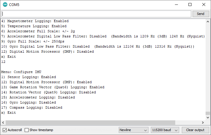
Once the DMP is enabled, you can select six-axis quaternion (Quat6) or nine-axis quaternion (Quat9) data for logging, plus the raw accelerometer, gyro and compass data. Quat6 only makes use of the accelerometer and gyro data. Quat9 includes the magnetometer (compass) data and provides absolute orientation with respect to magnetic North.
The quaternions Q1-Q3 are logged to SD card. You can manually calculate Q0 and the Euler angles (roll, pitch and yaw) from the logged data. There is a new stand-alone example called IMU_DMP_Quat6 in the GitHub repo which shows how to do that.
Please note that the DMP requires calibration. You will need to slowly rotate the OLA around all three axes and hold it stationary for a few seconds in all six orientations before the Quat9 data becomes well behaved.
Option 4 from the main menu will open the menu to configure serial logging:
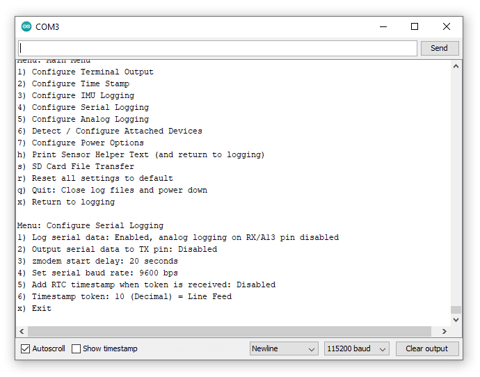
Serial logging on the RX pin (13) is enabled by default and the OLA is expecting data at 9600 baud (bits per second).
You can disable or re-enable serial logging using option 1.
As of firmware v1.6, option 2 can be used to enable or disable streaming of the sensor data to the serial TX pin. Serial data is transmitted using the same CSV format as the data which is logged to SD card or displayed on the terminal.
Option 3 can be used to set the start delay for ZMODEM file transfers through the SD Card File Transfer menu. See “SD Card File Transfer” for details.
Option 4 can be used to change the serial logging baud rate. Most older GNSS modules output data at 9600 baud, but the newer ones use 38400 baud. Any valid baud rate up to 500000 [1] can be used.
As of firmware 1.9, option 5 will allow you to add timestamps to your serial log file. When enabled, a timestamp will be added whenever the timestamp token is received. You can use option 6 to change the value of the token. Common values will be 10 (Line Feed), 13 (Carriage Return) or maybe 27 (Escape). You can select any value from 0 to 255. Options 1, 2 and 10 in the Time Stamp Menu control if the date, time and/or microseconds are added.
Option 5 from the main menu will open the menu to configure analog logging:
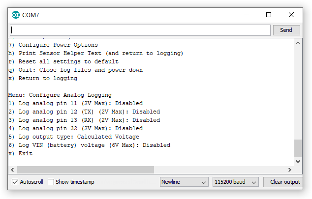
All four breakout pins (32, TX, RX and 11) can be used to log analog voltages up to a maximum of 2.0V. Analog logging is disabled by default but can be enabled with options 1, 2, 3 and 4.
Please be aware that analog logging and some of the OLA’s other logging features are mutually-exclusive:
Option 5 can be used to toggle between logging voltages (0.0V to 2.0V) and raw Analog to Digital Converter (ADC) units (0 to 16383).
Option 6 can be used to enable logging of the battery / bus voltage VIN. This is a useful way to log how quickly your battery discharges. Please note that this option is not supported on the older SparkX version of the OLA.
Option 6 from the main menu will open a menu which allows you to configure the settings for all devices attached to the Qwiic bus. For example, if you have an MS8607 PHT sensor, LPS25HB pressure sensor and an SHTC3 humidity sensor attached to the OLA, the menu will look like this:
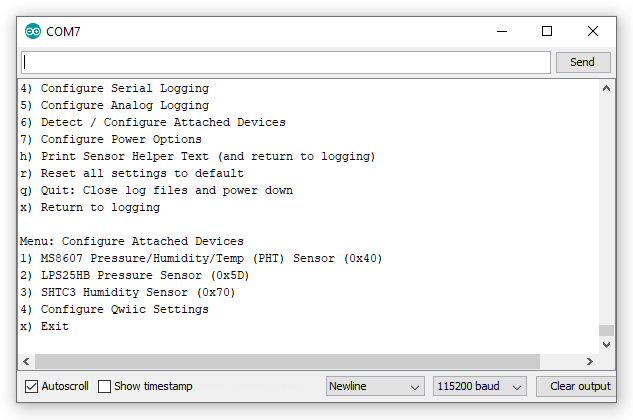
Just like for the built-in IMU sensor (if it is populated), if you open any of the menus you will be presented with a set of options where you can enable/disable logging from that sensor completely, or select which sensor values to log:
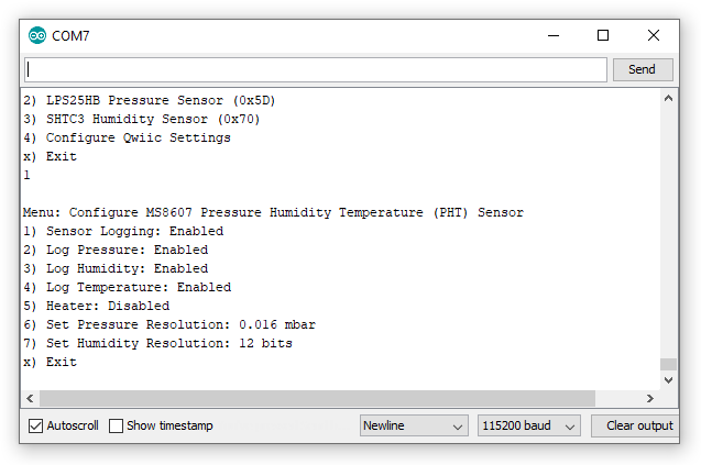
If the sensor has any configurable settings, those will be shown too.
There is an option on the devices menu which allows you to configure options for the Qwiic bus itself:
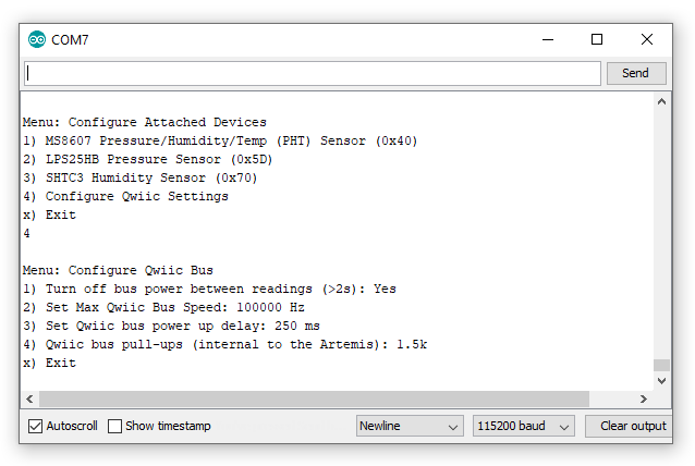
If you are using long logging intervals, set through the Configure Terminal Output menu, you can choose to completely turn off any sensors attached to the Qwiic bus while the Artemis is sleeping between readings. Use option 1 to toggle this setting. Please be aware that some sensors do not enjoy being turned off. GNSS sensors in particular need time to establish a fix even if they are performing a “hot start”. You can counteract this by setting a longer power up delay using Option 3.
Option 2 allows you to set the maximum speed for the Qwiic I2C bus. Valid values are 100000 and 400000 Hz. Please note that some sensors can only operate at lower bus speeds. The value you enter here is the maximum speed that will be used and may be ignored depending on what sensors are connected.
Option 3 allows you to adjust the delay between turning on the Qwiic bus power and logging being (re)started. Some sensors require more time than others to begin operation after the power is reconnected; this option sets the minimum time the OLA will wait before attempting to communicate with the Qwiic devices. If you have a ‘slow’ device like the SCD30 attached, the power up delay is automatically extended to 5 seconds. If you have a u-blox GNSS module attached and you want to give it time to establish a fix before the position data is read, you can extend the power up delay to a maximum of 60 seconds.
Option 4 is for advanced use and allows you to specify the value of the I2C pull-up resistors internal to the Artemis. For sensors like the u-blox GNSS modules, it is beneficial to disable the pull-ups completely by setting the value to zero. The other possible values are: 1.5k, 6k, 12k and 24k.
As of firmware v1.11, the OLA supports data logging from the MAX30101 Pulse Oximeter and Heart Rate Sensor .The Oximeter has two breakout pins, RST and MFIO, which need to be connected to Pin 32 and Pin 11 on the OLA. Because the Oximeter needs exclusive access to these pins, you need to enable detection of the Oximeter through this menu.
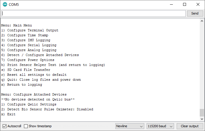
Enabling Oximeter detection means that you cannot use pins 32 and 11 for their other functions (analog logging, stop logging, triggering, fast/slow logging). You will see a warning message asking you to confirm that you want to proceed:
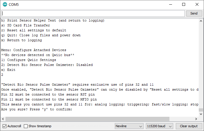
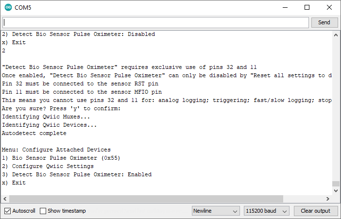
After pressing "y", the Oximeter will be detected and you can configure it in the same way as any other Qwiic sensor.
Option 7 from the main menu will open the menu to configure the power options:
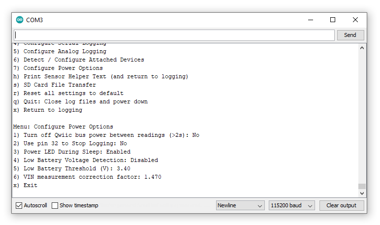
Option 1 is a repeat of the bus power option on the Configure Qwiic Bus menu. It allows you to disable power to the Qwiic bus completely while the OLA is asleep.
Breakout pin 32 can be used to make the OLA stop logging, close the SD log files safely and go into deep sleep. This feature can be enabled using option 2. If this option is enabled, pulling pin 32 to GND will stop the OLA logging. Please note that enabling this feature will prevent analog logging on pin 32. Please see “Low Power Considerations” for further details.
For low power applications, the PWR LED can be turned off while the OLA is asleep between readings. This setting can be toggled using option 3. Please note that this option is not supported on the older SparkX version of the OLA.
As of firmware v1.6, option 4 can be used to enable or disable low battery detection. The low battery threshold voltage can be set using option 5. When low battery detection is enabled, the OLA will automatically stop logging and go into deep sleep when the battery voltage falls below the threshold.
The OLA uses a high impedance two resistor divider to measure the VIN battery / bus voltage. This requires a correction factor to convert the reading into the true voltage. You may need to change this value to compensate for the actual resistor values on your OLA. If you select option 6 you will be asked to measure and enter the true voltage between the MEAS pin and GND. You will need a multimeter to measure the voltage. The correction factor will be adjusted according to the value you enter. Please note that this option is not supported on the older SparkX version of the OLA.

As of firmware v1.6, the SD Card File Transfer menu can be used to access the files on the SD card:
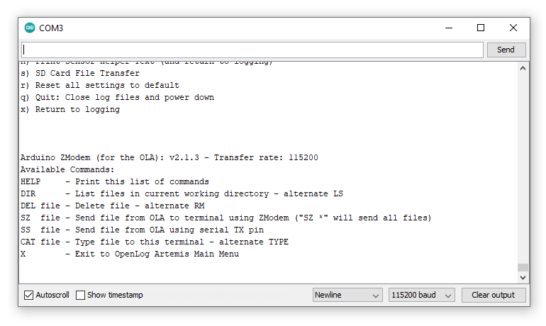
As of firmware v1.9, you can also transfer files via the TX and RX pins. Please see option 14 in the Configure Terminal Output menu. Note: you can only have the SD Card File Transfer menu open on either USB or TX/RX. (You cannot have it open on both at the same time.)
When the SD Card File Transfer menu is open, the OLA will respond to a number of commands:
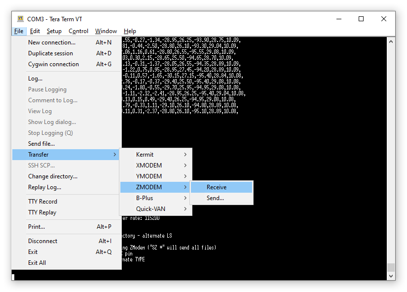
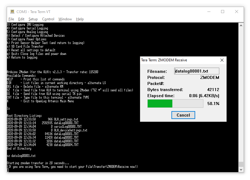
The ZMODEM file transfer protocol has been around since 1986 and allows files to be transferred between terminal emulators. The Tera Term terminal emulator still supports ZMODEM. You will find the file-receive option in the File > Transfer menu:
With the SD Card menu open, you can start a file transfer by typing sz followed by the filename into Tera Term:
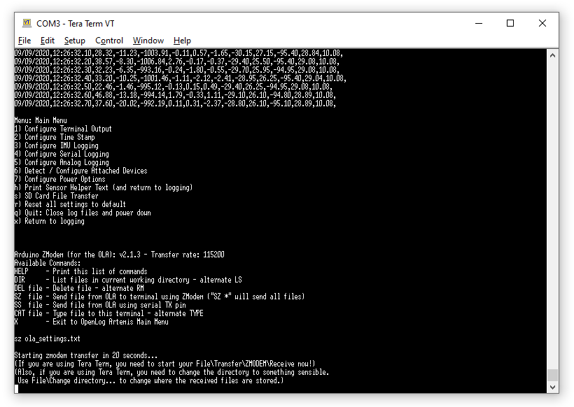
Start the ZMODEM receive in Tera Term and, after 20 seconds, the transfer will take place:
You may also want to use the File > Change directory… option in Tera Term to change the directory where the received files are stored.
New sensors and features are being added all the time and we’ve made it really easy for you to keep your OLA up to date. We’ve written a simple Generic User Interface (GUI) which can be used on multiple platforms (Windows, Linux and OSX). A few mouse clicks will update your OLA.
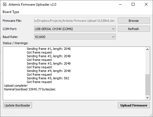
You will find full instructions in the GitHub repo.
Ambiq, the manufacturer of the Apollo3, has done years of research into something they call Sub-threshold Power Optimized Technology (SPOT™). This is a fancy description of a power saving technique that works by lowering the logic level voltages necessary to indicate a 1 or a 0. By doing so at the silicon level, Ambiq has managed to eke out a 48MHz processor which can draw less than half a milliamp.
The Artemis processor can also be put into a deep sleep state where it draws approximately 18µA of current. For the OLA, we take advantage of this by putting the Artemis into this deep sleep state:
In deep sleep:
We have included a Seiko Instruments ML414H rechargeable battery on the OLA to provide power while the Artemis is in deep sleep so it can keep its Real Time Clock (RTC) running. Now, we have tried to cover all of the options here, but there are some things you need to be aware of if you want to reduce the OLA power consumption to the absolute minimum. The Seiko battery can only provide µA of current, which is enough to power the Artemis while it is in deep sleep, but it cannot provide enough current to let the Artemis run at usual speeds. Resetting the Artemis brings it out of deep sleep and into normal operation, so you need to make sure that external power or a battery is connected first.
The OLA 3.3V regulator is an AP2112K which has a low drop-out voltage (approximately 250mV) and a low quiescent current of 55µA. If you cut the MEAS jumper link and use the MEAS pins to measure the OLA’s current draw from external power or the LiPo battery, you will see:
The PSWC pins can be used to power down the AP2112K regulator, reducing the regulator’s quiescent current to well below 1µA.
If the OLA’s logging interval is greater than 2 seconds, the Artemis automatically goes into deep sleep between reads. An RTC alarm is used to wake the Artemis up for the next read.
The OLA goes into deep sleep automatically:
Once in deep sleep, the Artemis can only be woken by:
Don’t forget that the RTC battery cannot provide enough current to run the Artemis at normal speeds, so you need to make sure that power is connected before generating a reset. If you do accidentally press the RST button while the power is disconnected:
So, how should you put all of this together for your low power logging application? Here are a couple of suggestions.
One of our favorite ways is to connect up external “stop logging” and “reset” buttons to the RST and pin 32 breakout pins. If stop logging has been enabled using the configuration menus, pulling pin 32 to GND via a push-to-close button will gracefully stop the logging and place the OLA into deep sleep. Pulling the RST pin to GND will reset the Artemis, waking it up again and logging is restarted. We like this method because the log file on the SD card is closed gracefully, making sure that no data is lost. You can think of the pin 32 and RST buttons as “Off” and “On” buttons. When “Off”, the current drawn from a LiPo battery will be no lower than 80µA because the 3.3V regulator is still enabled.
As we described above, the PSWC pins can be used to disable (switch off) the OLA’s 3.3V regulator. Connecting the pins together via a SPST toggle switch pulls the regulator’s EN pin low and disables it. This causes the 3.3V rail to collapse. If the Artemis is running, the voltage supervisor will generate an interrupt to immediately put the Artemis into deep sleep. Because the 3.3V rail has already collapsed, the Artemis cannot close the log file on the SD card gracefully. The OLA syncs the log file regularly while it is logging, but there is a small risk of data loss if you use this method to disable the OLA.
A better method is to use a “stop logging” button as described above. Pressing the stop logging button will gracefully close the log file and place the Artemis into deep sleep. Then you can disable the regulator safely via the PSWC pins. In this state, the OLA will draw less than 1µA from external power or LiPo battery, the RTC battery will provide the 18µA needed by the Artemis to keep its RTC running.
The Artemis will stay in deep sleep when you toggle the regulator back on again. You will need to reset it via a reset button to start it logging again.
As described in the Configure Terminal Output section, you can also use slow logging to conserve your battery life. You can choose to go into slow logging mode: according to the state of Pin 11; or once per day (with configurable start and end times).
OpenLog Artemis is capable of logging high-rate raw UBX messages from the latest u-blox Global Navigation Satellite System modules. This is extremely helpful for logging and then post processing the data using the popular RTKLIB. Because of the complexity and necessity for data bandwidth, we’ve created a separate firmware for OLA which can be found below. Want to log RAWX, SFRBX, TIM-TM2 or RELPOSNED messages in UBX format? This is the firmware for you!
OpenLog Artemis supports logging from the ADS122C04 Analog to Digital converter found on the Qwiic PT100. The standard OLA firmware will let you log precision temperature from the Qwiic PT100 but what if you want to go further? We’ve created a separate firmware for the OLA which can turn it into a seismometer / geophone logger for earthquake detection! This firmware uses the ADS122C04 to sample the signal produced by the SM-24 Geophone and logs Fast Fourier Transformed frequency data to SD card. Want to study seismic events? This is the firmware for you!
Below are a few troubleshooting tips and frequently asked questions that can come up when working with the OpenLog Artemis. Make sure to check the following scenarios for possible solutions and answers to your questions.
Your OLA is probably in deep sleep and needs to be woken up. Give the RST button a press and you should see the STAT LED light up immediately and flash once logging has started.
Did you check the battery polarity? Some batteries have the opposite polarity as opposed to the batteries in the SparkFun catalog. Unfortunately, connecting one of those will destroy your OLA.
As of firmware v1.11, the OLA supports exFAT SD cards in addition to FAT32 cards. Please ensure your card is formatted correctly; we recommend the SD Association Formatter.
Please have a look at the “Low Power Considerations” section. The RTC will reset if: the RTC battery discharges; you attempt to reset (wake) the OLA without a power source connected.
Stop Logging needs to be enabled through the configuration menus. Please see the “Configure Power Options” section for more details.
This can happen if the log file is not closed correctly or if the SD card is removed before the power is turned off. The data is probably still on the card, but the File Allocation Table has not been updated correctly. We recommend adding a stop logging button to completely prevent this.
There are active disk editor tools which you can use to search for and recover your data, but this is something for advanced users only.
Each device on an I2C (Qwiic) bus must have a unique address. If your sensors cannot be configured with unique addresses, you will need to use a Qwiic Mux to isolate them. Please see “Qwiic Sensors and Muxes” above for further details.
Now that you've successfully got your OpenLog Artemis up and running, it's time to incorporate it into your own project! For more information, check out the resources below:
Or check out this blog post for ideas.
learn.sparkfun.com | CC BY-SA 3.0 | SparkFun Electronics | Niwot, Colorado