MiniMoto DRV8830 Hookup Guide
This Tutorial is Retired!
This tutorial covers concepts or technologies that are no longer current. It's still here for you to read and enjoy, but may not be as useful as our newest tutorials.
 SFUptownMaker
Hardware
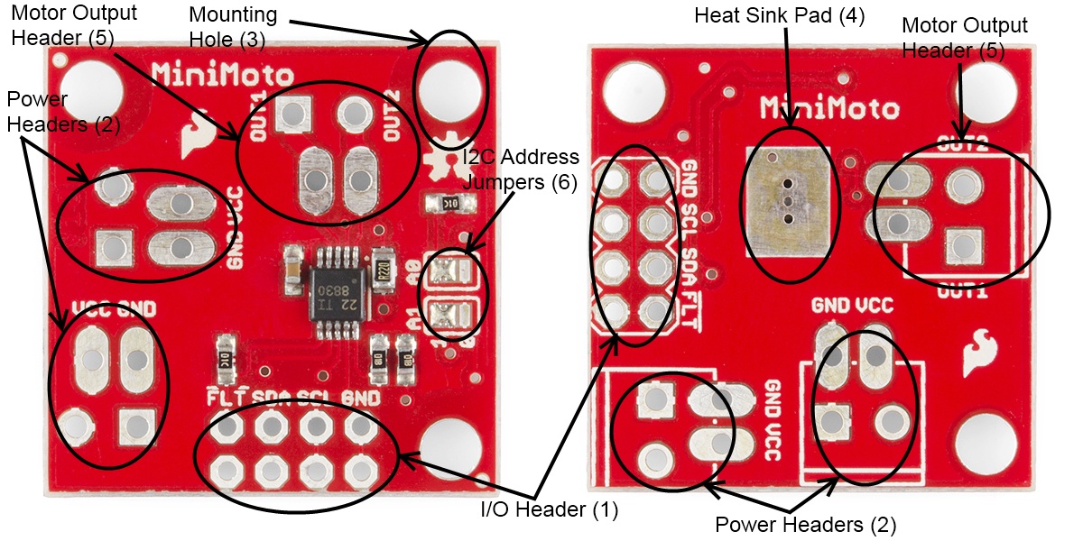
The MiniMoto is a pretty simple board; here's a little walkthrough to get you up-to-speed on its various features.
- I/O header (1) - Two rows of .1" headers provide access to the I2C lines, the FAULT signal, and a ground reference. One row is provided to connect to the controlling CPU; the other can be jumped to the next MiniMoto board. The FAULT line is open-drain, which means that the signal will assert low during a fault condition regardless of the number of MiniMoto boards connected in parallel.
- Power headers (2) - Two power header connections are provided -- one for input and one to pass power through to the next MiniMoto board. There are two sets of pads for each of these: one which is spaced for .1" headers and one spaced for a 3.5mm screw terminal.
- Mounting holes (3) - Three mounting holes are in the corners of the boards; the spacing along the edges is 1" (25mm). The holes are sized for #4-40 screws but a metric M3 should work just as well.
- Bare metal heat sink pad (4) - On the opposite side of the board from the components is a piece of bare copper which is fairly tightly coupled to the power pad on the underside of the drive IC. This pad is sized to fit our small heatsink for improved heat dissipation; you'll need to hold it down with either thermal tape or thermal paste.
- Motor output header (5) - The motor output goes to this header, which has provision for either .1" pins or the same 3.5mm screw terminal used on the power connections.
- I2C address select jumpers (6) - Each board has address selection jumpers that allow the user to set one of 9 addresses. See the next page for explanations of how to set addresses with these jumpers.
Electrical Considerations
The MiniMoto is designed to operate from 2.75V to 6.8V and to drive motors at up to 900mA of current. The minimum logic level required to communicate reliably with the chip varies with the supply voltage: however, at the maximum operating voltage of 6.8V, the minimum the chip will recognize as a high is 3.13V, so a 3.3V input will be recognized comfortably.
The I2C bus can operate at up to 400kHz, depending on the additional load on the bus. While the chip is capable of communications at up to 400kHz, a heavily loaded bus may require that the data rate be dropped to maintain signal integrity. The MiniMoto library operates at 100kHz, which should low enough to work in most conditions.