$9.95
Want to add a little graphic pizzazz to your Arduino project? Do you need to display diagnostic information without resorting to serial output? Or maybe you want to learn a little game theory while creating a fun, Arduino-based video game. These are just a handful of example applications for the Micro OLED Breakout.
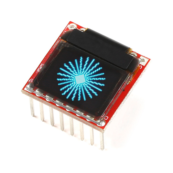
The Micro OLED Breakout Board breaks out a small monochrome, blue-on-black OLED. It's 64 pixels wide and 48 pixels tall, measuring 0.66" across. It's micro, but it still packs a punch -- the OLED display is crisp, and you can fit a deceivingly large amount of graphics on there. Most important of all, though, is the Micro OLED is easy to control over either an SPI or I2C interface.
In this tutorial we'll give you a brief introduction to the OLED and the breakout, then we'll jump into example hardware hookups and code. The tutorial is split into the following sections:
In addition to the display, you'll also need a few components and tools to follow along with this tutorial. Here is what we used to get the display up-and-running:
There are many ways to complete the hookup, though. In general, you'll need:
Before getting started with the Micro OLED Breakout, there are a few concepts you should be familiar with. Consider reading some of the tutorials below, before continuing on with this one.
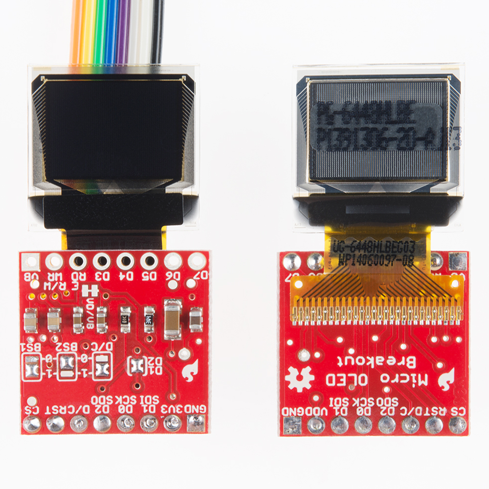
In total, the Micro OLED Breakout provides access to 16 of the OLED's pins. Fortunately, though, you'll only need about half of them to make the display work.
The top row of pins (in the image above) breaks out everything you'd need to interface with the OLED over an SPI or I2C interface. Those pins are:
| Pin Label | SPI Function | I2C Function | Notes |
|---|---|---|---|
| GND | Ground | Ground | 0V |
| 3V3 (VDD) | Power | Power | Should be a regulated 3.3V supply. |
| D1 (SDI) | MOSI | SDA | Serial data in |
| D0 (SCK) | SCK | SCL | SPI and I2C clock |
| D2 (SDO) | MISO | — | Can be unused in SPI mode. No function for I2C. |
| D/C | Data/Command | I2C address selection | Digital pin to signal if incoming byte is a command or screen data. |
| RST | Reset | Reset | Active-low screen reset. |
| CS | CS | — | SPI chip select (active-low) |
The pins on the bottom are mostly only used if you need to control the display over a parallel interface. D3-D7 are the last 5 bits of the parallel data bus. E/RD acts as either an enable/disable pin, or a read/write control, depending on the parallel bus configuration. The RW/WR pin is either used as a read/write control or a write latch.
The VB pin allows you to individually power the VBAT line of the display. The supply for VBAT should be between 3.3V and 4.2V (LiPo battery-ish supply). If you'd like power this line individually, pay extra-special attention to the VD/VB jumper section below.
Those bottom eight pins were simply broken out for complete-ness. If you're controlling the display via either SPI or I2C, you can safely ignore them.
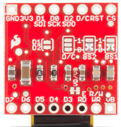
With the board flipped over, you'll notice there are five jumpers. The majority of these jumpers are used to switch between SPI and I2C mode. As the board ships, these jumpers are set to configure the display in SPI mode.
Here's an overview of each jumper, moving from left-to-right, top-to-bottom in the picture above:
| BS2 | BS1 | Interface |
|---|---|---|
| 0 | 0 | SPI |
| 0 | 1 | I2C |
| 1 | 0 | 8-bit Parallel (6800) |
| 1 | 1 | 8-bit Parallel (8080) |
That brief overview should cover the 99% use case. Consult the schematic and the notes therein if you have any questions about jumpers or pins.
Before you solder anything to the Micro OLED Breakout, take some time to think about how you're going to use it. Are you just prototyping with it? Sticking it on a breadboard? Maybe all you need to do is solder some headers on there. Are you enclosing it? Embedding it into a project? In that case, maybe you'll want to solder wires to the pins instead.
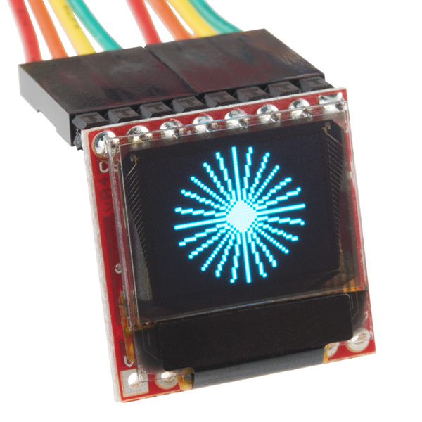
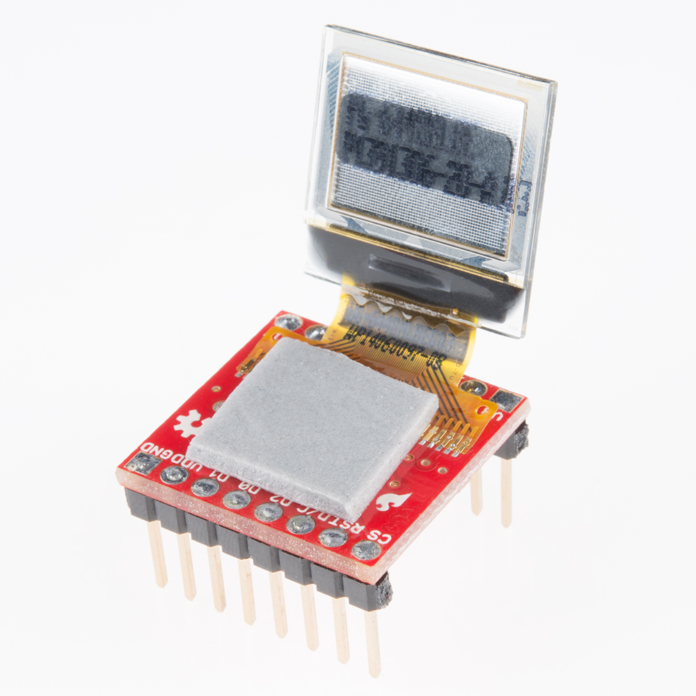
Also think about how you want the screen to be visible. The board is designed so you can either fold the display over, or have it flop off the edge of the board. The screen's orientation will determine which side of the board you'll need to solder to.
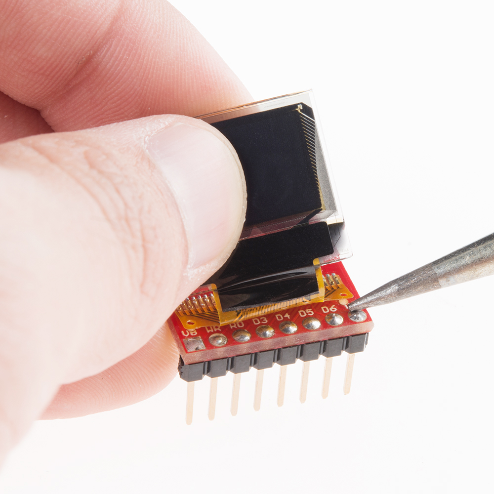
Even if you're not going to use the extra eight pins, try to solder headers to them if you can. This will help balance the display if you're plugging it into a breadboard. Just take care not to burn the screen's connector as you solder these pins -- you can gently pull it back while applying the solder.
After soldering, you may want to secure the display with some tape -- especially if you're going with the "fold-over" method. Double-sided foam tape is perfect for this application.
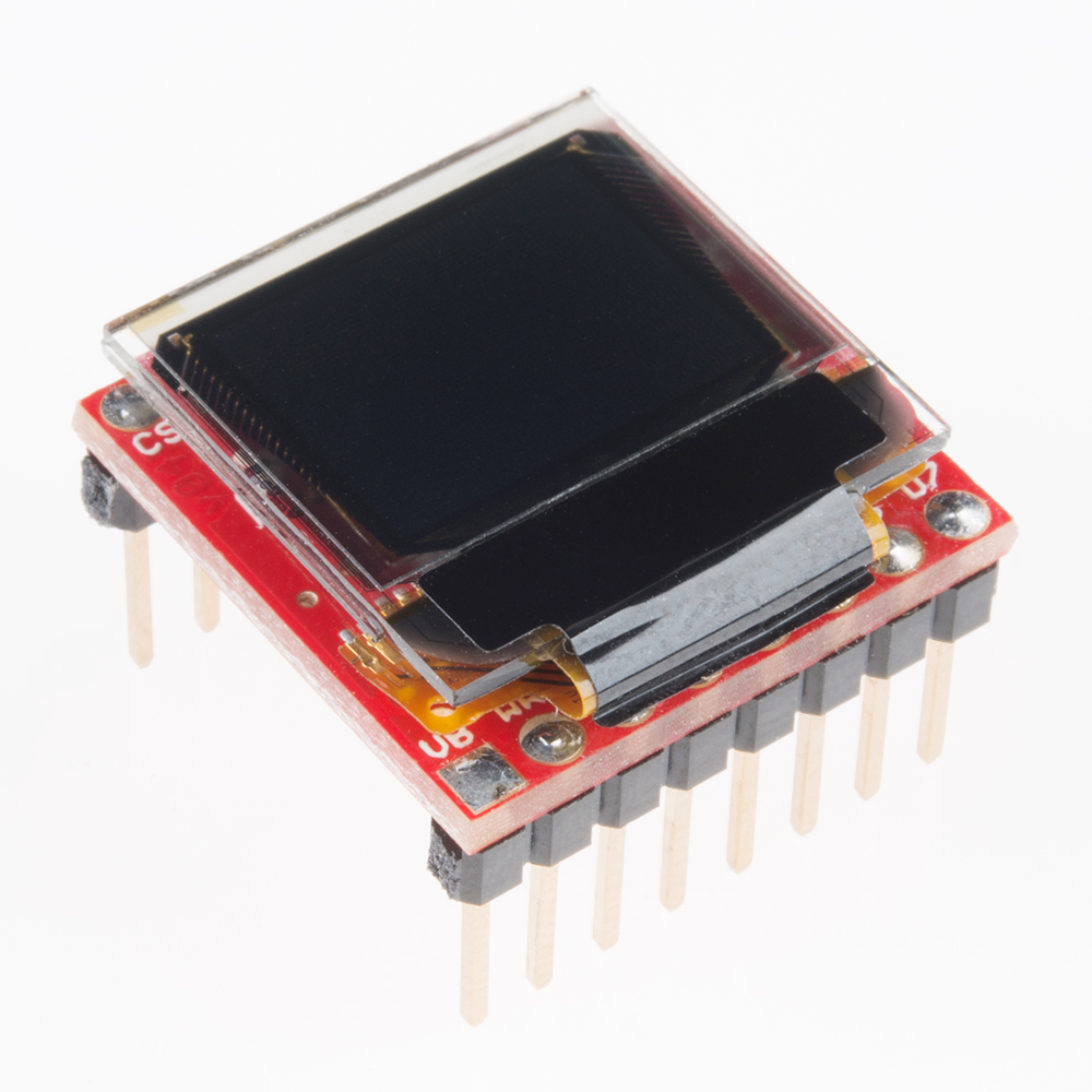
Fold the display over and it should fit perfectly within the PCB's outline.
If you're controlling the display over I2C, you'll need to make a few modifications to the jumpers:
Once you're done setting jumpers, the back of the board should look a little something like this:

Now that your breakout is all soldered-to and assembled, it's time to wire it up. In this section we'll go over to example hookups, depending on whether you'd like to use SPI or I2C to control the display.
If you're not sure which interface to use, we recommend going with SPI, which will give you the fastest transfer rate and screen refresh speed.
We'll be using the Arduino's hardware SPI pins in order to achieve the fastest data transfer speed. That means we'll need to use pins 13, 11, and 10 as the SCLK, MOSI, and CS pins. The other pins -- RST and D/C -- can be connected to any available digital pin on the Arduino.
Here's the example hookup:
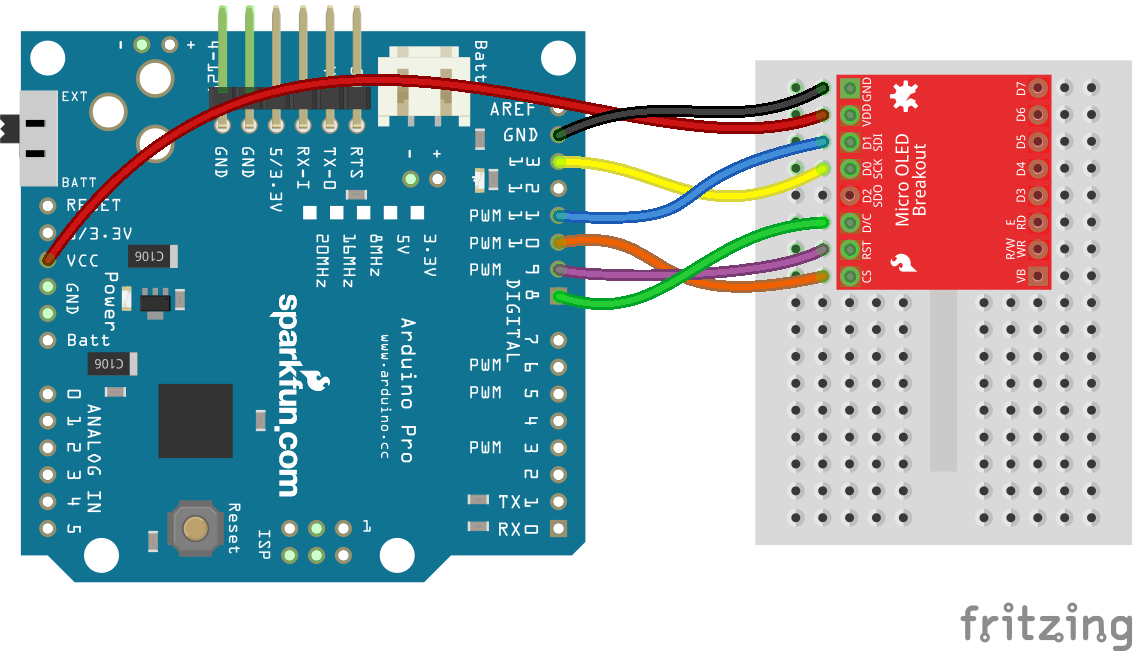
Make sure your display is powered at 3.3V and not 5V!
The benefit of I2C is the lower pin count -- this hookup only requires three wires, besides power and ground -- but you do sacrifice some speed for fewer wires.
In this case, SDA and SCL must be tied to the Arduino Pro's pins A4 and A5 respectively. RST can be tied to any other digital pin, we're using 9.
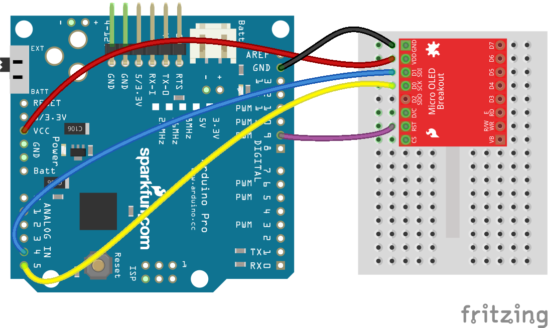
While I2C affords you a few extra available pins, it is quite a bit slower than SPI. If you don't need a fast framerate, though, I2C is a great option.
Soldering? Check. Wiring? Check. On to the firmware. Let's make the display blink!
To make controlling the OLED as easy as possible, we've adapted an Arduino library for it. Using the library, you can draw anything from pixels to shapes and even text. To download the library, click the button below, or grab the latest version from our GitHub repository.
Then install the library in your Arduino sketchbook. If you need any guidance installing the library, check out our Installing an Arduino Library tutorial.
Next, load up the demo example that's included with the library. After installing the library, open Arduino. Then navigate to File > Examples > SFE_MicroOLED > MicroOLED_Demo.
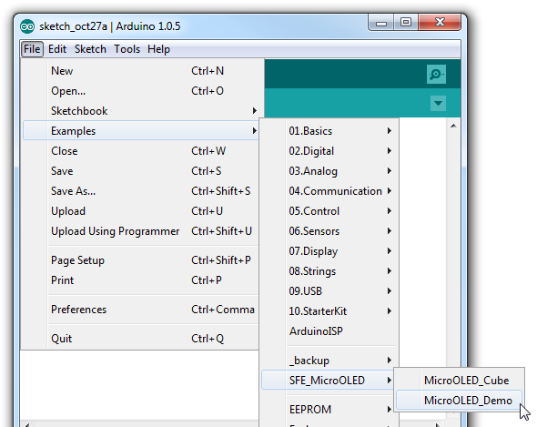
Make sure your Board and Serial Port are set correctly and upload!
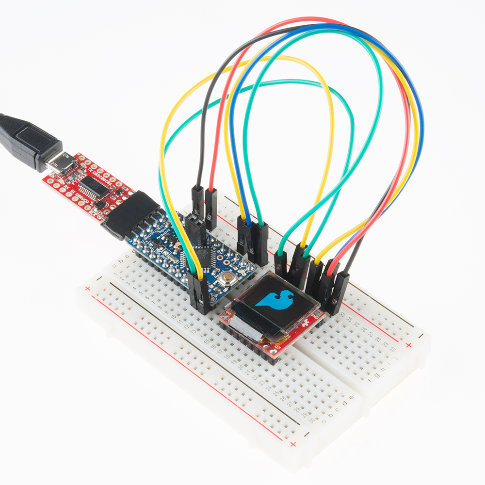
The demo example will show off a lot of what the OLED can do. For more fun, check out the other examples included with the library.
Now that you've loaded up the example, and proven out your display and hookup, it's time to get started writing your own application! Before you get started, here's a quick rundown of the SFE_MicroOLED library.
At the top of your code, of course, you'll need to include the SFE_MicroOLED library. On top of that, you'll also need to include the SPI and Wire libraries so the SFE_MicroOLED library has access to those interfaces.
language:c
#include <SPI.h>
#include <Wire.h>
#include <SFE_MicroOLED.h>
After you've included the library, you can create a MicroOLED object in the global variable area of your code. This is where you'll tell the library whether you're using SPI or I2C, and which pins are driving the display.
language:c
#define PIN_RESET 9  // Connect RST to pin 9 (req. for SPI and I2C)
#define PIN_DC    8  // Connect DC to pin 8 (required for SPI)
#define PIN_CS    10 // Connect CS to pin 10 (required for SPI)
//#define DC_JUMPER 0 // Set to either 0 (default) or 1 based on jumper, matching the value of the DC Jumper
// Also connect pin 13 to SCK and pin 11 to MOSI

// Declare a MicroOLED object. The parameters include:
// 1 - Reset pin: Any digital pin
// 2 - D/C pin: Any digital pin (SPI mode only)
// 3 - CS pin: Any digital pin (SPI mode only, 10 recommended)
MicroOLED oled(PIN_RESET, PIN_DC, PIN_CS); //Example SPI declaration, comment out if using I2C
//MicroOLED oled(PIN_RESET, DC_JUMPER); //Example I2C declaration, uncomment if using I2C
If you're using SPI to talk to the display, define three parameters to tell the library which pins you have RST, D/C and CS connected to, respectively.
In the example above we've called our MicroOLED object oled, but you can call it anything you'd like. You can even create more than one, if you have more displays connected to your Arduino.
The last step to the OLED setup should occur in the setup() function. Stick a oled.begin() function in there, which will initialize the display and update all sorts of behind-the-scenes settings for you.
language:c
setup()
{
    delay(100);
    //Wire.begin(); //set up I2C bus, uncomment if you are using I2C
    // Before you can start using the OLED, call begin() to init
    // all of the pins and configure the OLED.
    oled.begin();
}
DC_JUMPER to the either 0 or 1 based on the jumper.#define DC_JUMPER 0 // Set to either 0 (default) or 1 based on jumper, matching the value of the DC Jumper
//MicroOLED oled(PIN_RESET, PIN_DC, PIN_CS); //Example SPI declaration, comment out if using I2C
MicroOLED oled(PIN_RESET, DC_JUMPER); //Example I2C declaration, uncomment if using I2C
You will also need to initialize the bus in the setup():
delay(100);
Wire.begin(); //set up I2C bus, uncomment if you are using I2C
Let's begin by drawing the simplest shape out there -- a pixel. Drawing anything requires at least two steps. First you have to tell the screen what you want to draw, then you have to tell it to draw it.
To draw a pixel, start by calling the pixel(int x, int y) function.
language:c
// Draw a pixel in the middle of the screen
oled.pixel(LCDWIDTH/2, LCDHEIGHT/2); // Add a pixel to the display buffer.
Then, after you've told the screen what to draw, use the display() function to execute.
language:c
oled.display(); // Draw whatever is in the display buffer.
The display() function re-draws the entire screen -- all 3072 pixels. It takes a relatively long time to execute the command, so try not to do it too much.
Now that we know how to draw pixels, it'll be easy to draw all sorts of shapes.
To draw a line, you need two sets of x/y coordinates, the line will be drawn between them. Here's an example:
language:c
int x0 = 7; int y0 = 7;   // (x0,y0) = (7, 7)
int x1 = 42; int y1 = 24; // (x1,y1) = (42, 24)
oled.line(x0, y0, x1, y1);  // Draw a line from (x0,y0) to (x1,y1);
oled.display(); // Draw to the screen
Things are a little different if you want to draw a rectangle. In this case, you give it a x/y coordinate to start at, then a width and a height.
language:c
int x0 = 7; int y0 = 5;
int width = 24;
int height = 13;
oled.rect(x0, y0, width, height);  // Draw a rectange from (7,5) to (31,18)
oled.display(); // Draw to the screen
The rectangle will be drawn from (x0, y0) to (x0+width, y0+height).
Want to fill that rectangle? Use the rectFill function instead!
language:c
oled.rectFill(7, 5, 35, 5); // Fill a rectangle from (7, 5) to (42, 10)
oled.display(); // Draw to the screen
Circles require a set of coordinates for the middle, and then a radius.
language:c
int radius = 13;
// Draw a 13-pixel radius (26-pixel diameter)
// circle centered in the middle of the display:
oled.circle(LCDWIDTH/2, LCDHEIGHT/2, radius);
As with the rectangle function, you can also fill the circle with circleFill:
language:c
oled.circleFill(42, 20, 7); // Fill a circle, 7 radius, centered at (42, 20)
oled.display(); // Draw to the screen
In addition to basic shapes, you can also draw text with the SFE_MicroOLED library. There are a few settings to adjust before you get to texting, though. First, set the font type with setFontType(type). The parameter in this function can be either 0, 1, 2, or 3, each size gets progressively larger.
language:c
oled.setFontType(0);  // Set the text to small (10 columns, 6 rows worth of characters).
oled.setFontType(1);  // Set the text to medium (6 columns, 3 rows worth of characters).
oled.setFontType(2);  // Set the text to medium/7-segment (5 columns, 3 rows worth of characters).
oled.setFontType(3);  // Set the text to large (5 columns, 1 row worth of characters).
Here's a quick overview of each of the four font types:
| Font Type | Maximum Columns | Maximum Rows | Description |
|---|---|---|---|
| 0 | 10 | 6 | Smallest, 5x7-pixel characters. |
| 1 | 6 | 3 | Medium, 8x16-pixel characters. |
| 2 | 5 | 3 | 7-segment display style characters, 10x16-pixels each. |
| 3 | 5 | 1 | Large, 12x48 (the entire screen height) characters. |
Next, after setting the font type, define your text cursor with setCursor(x, y). This will define the top-left corner of the first character you print.
language:c
oled.setCursor(0, 0);  // Set the text cursor to the upper-left of the screen.
Finally, you can use the print(String/int/float) command to print whatever you want.
language:c
oled.print("Hello, world"); // Print a const string
oled.print(analogRead(0));  // Print an integer
oled.print(42.07);  // Print a float
oled.display(); // Draw to the screen
That covers the basics of the library, but it can do more. Check out the library's readme for a complete overview of the MicroOLED class. There you'll find more functions, like invert(boolean) flipVertical(boolean), flipHorizontal(boolean), and scrollRight(start, stop).
Here are a few helpful links that might help to answer any questions you may still have regarding the Micro OLED Breakout:
Now that you're well-versed in all things Micro OLED Breakout and its Arduino library, what are you going to make with it? Need some inspiration, check out these related tutorials and projects:
learn.sparkfun.com | CC BY-SA 3.0 | SparkFun Electronics | Niwot, Colorado