Mean Well LED Switching Power Supply Hookup Guide
 bboyho
 Hardware Assembly
Hookup Table
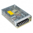
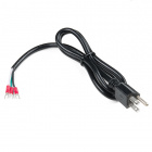
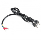
The following is the hookup table for connecting a wall adapter cable to a Mean Well power supply and then to your load. Ensure that the cable is not connected to a wall outlet when making the following connections between the cable and Mean Well power supply!
| 120VAC Outlet (North American Standard) | Mean Well Power Supply | Load (i.e. LED Strips) | Notes |
|---|---|---|---|
| LIVE/HOT Wire (Black) | ACL (Brown) | Input AC Voltage, Live/Hot wire | |
| NEUTRAL Wire (White) | ACN (Blue) | Input AC Voltage, Neutral Wire, Wider Blade on Wall Outlet Side | |
| V+ (Red) | 5V | Output Voltage (DC) | |
| V- (GND, Black) | GND | Output Ground (DC) |
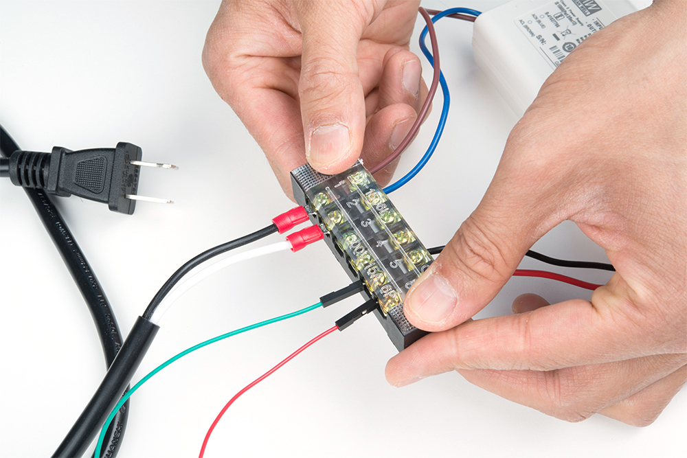
Connecting the AC Input Voltage w/ Screw Terminals
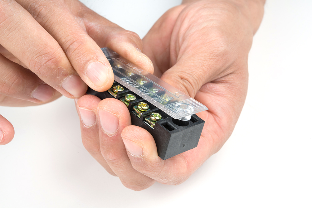
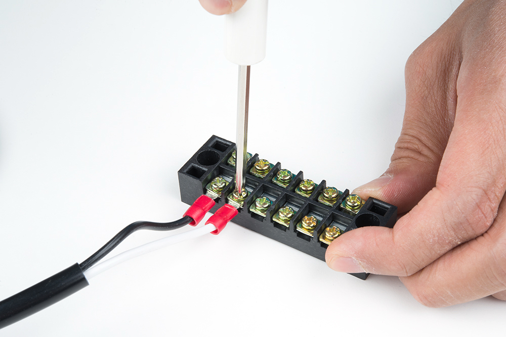
Before beginning, make sure the power cable is unplugged from the wall outlet. Carefully remove the plastic cover on the terminal block by wiggling it back and forth from the black housing.
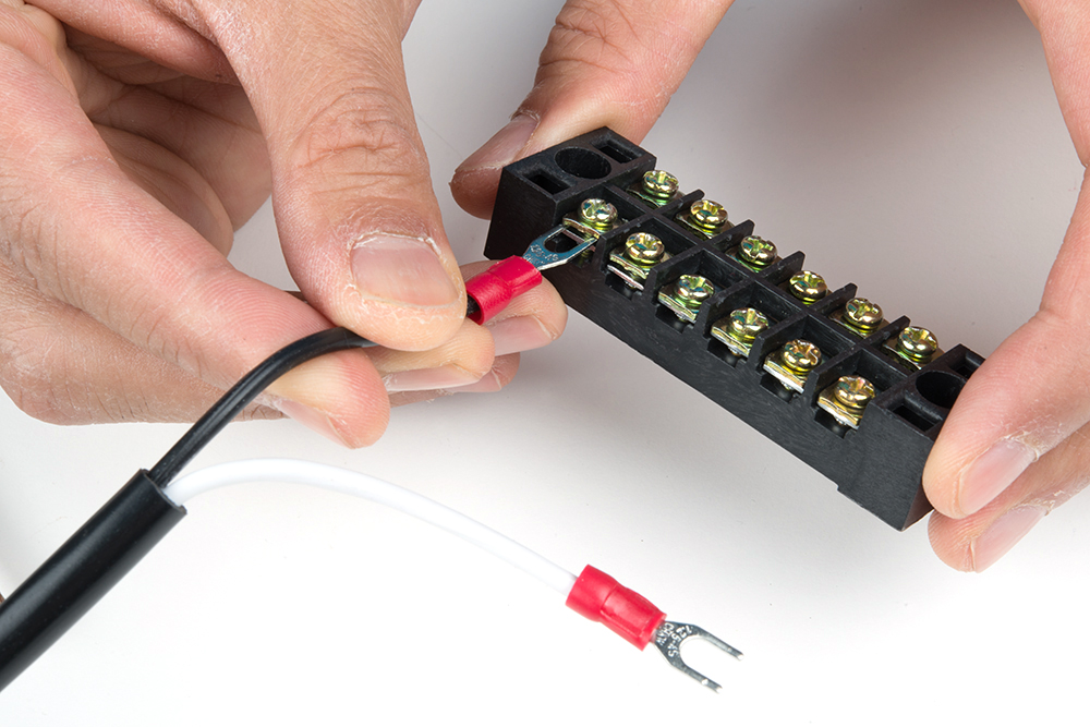
Insert the hot wire's spade connector into a terminal block between the metal plates.
 |
 |
Tighten the screw. Pull wire gently to see if it is secure.

Repeat for the neutral wire's spade connector.
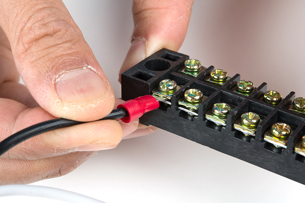
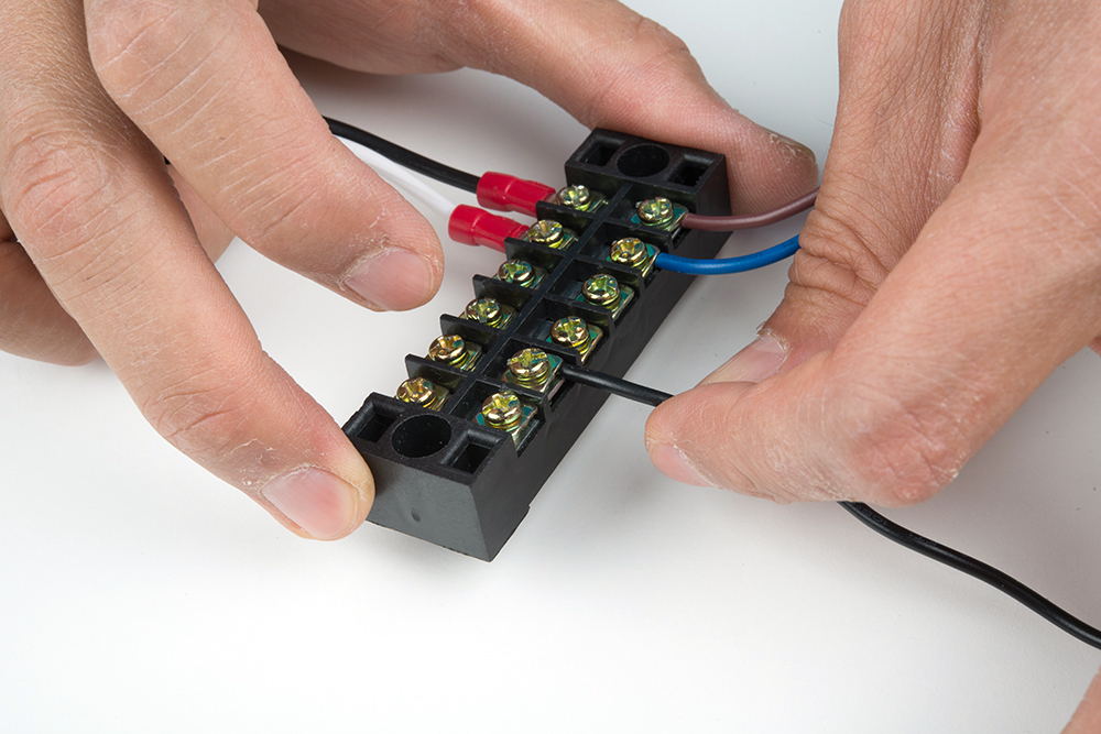
Connect the hot wire to the Mean Well's hot wire by inserting the wire between the metal plates and tightening the screw.
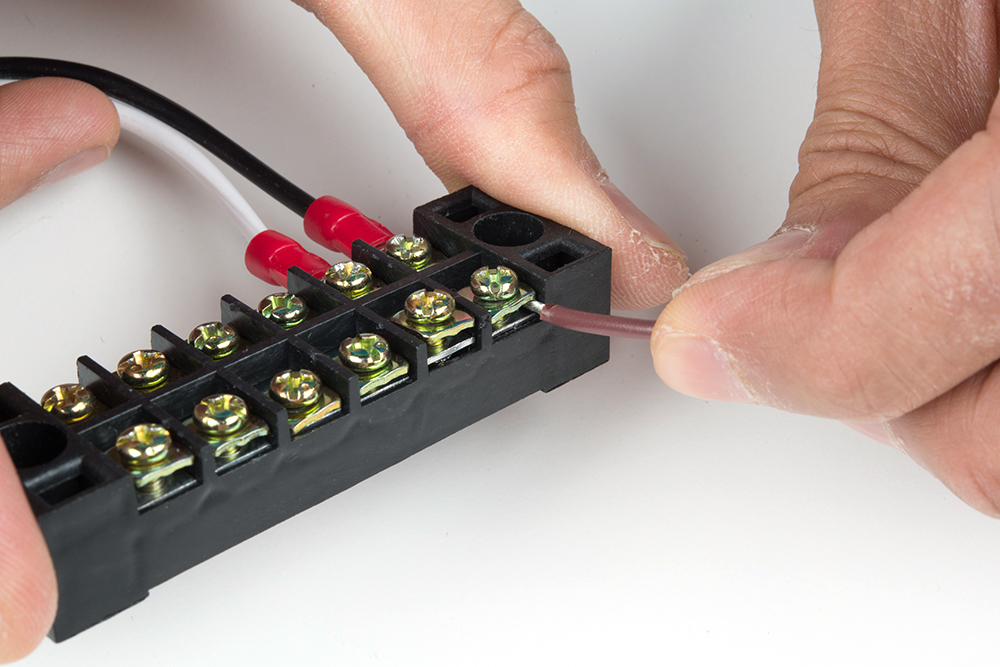
Remember to pull the wire gently to see if the connection is secure.
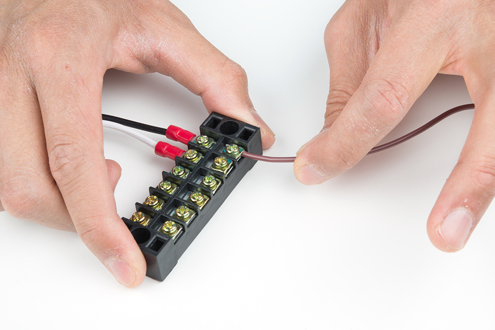
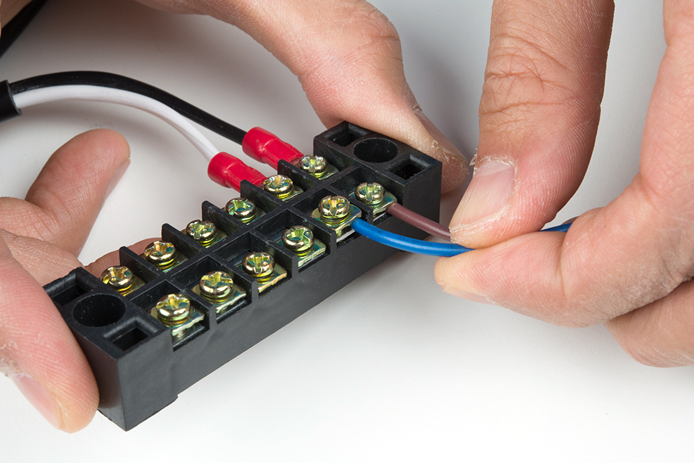
Repeat for the input neutral wire.
Connecting the DC Output Voltage w/ Screw Terminals
Connect your Mean Well power supply's output ground wire to one side of the terminal block.
Connect the output voltage's wire to another screw terminal.
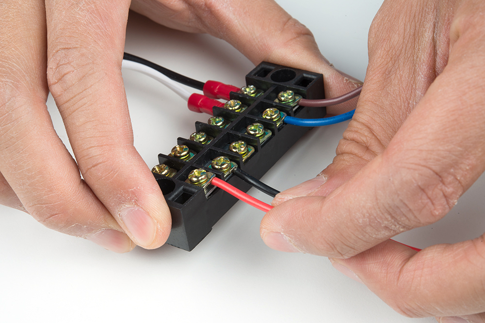
Connect your load wires to the other side of the Mean Well output voltage.
Other Methods of Connecting to the Mean Well Power Supply
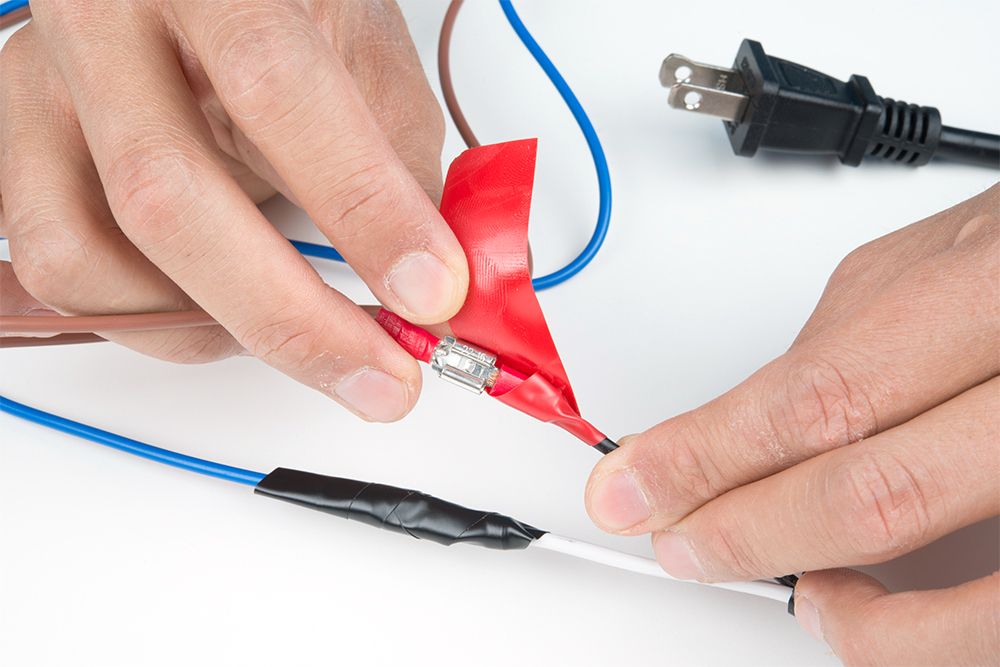
You can also splice the wires or use spade connectors depending on your preference. If you decide to connect with a spade connector, make sure that you are using the correct tool to properly crimp the connection. Needle nose pliers may not provide sufficient force to clamp the spade connector against the wires. Ensure that the power cable is unplugged from the wall outlet.
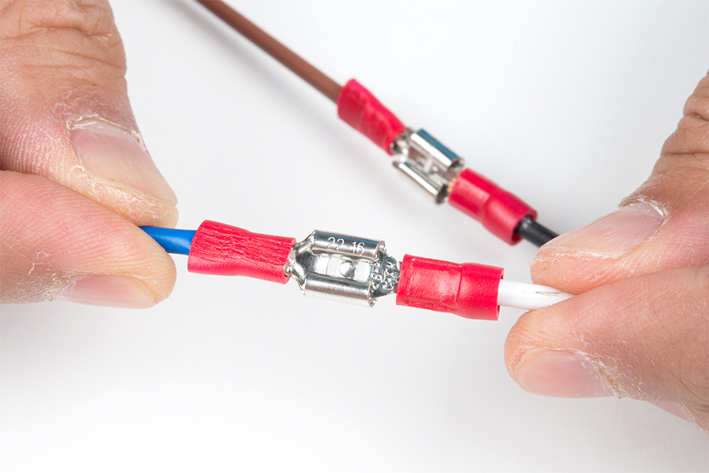
Remember to insulate your connections with electrical tape or heat shrink so that the connections are not exposed.
Once connected, make sure to test it out with a multimeter and surge protector before installing.
Testing the Output
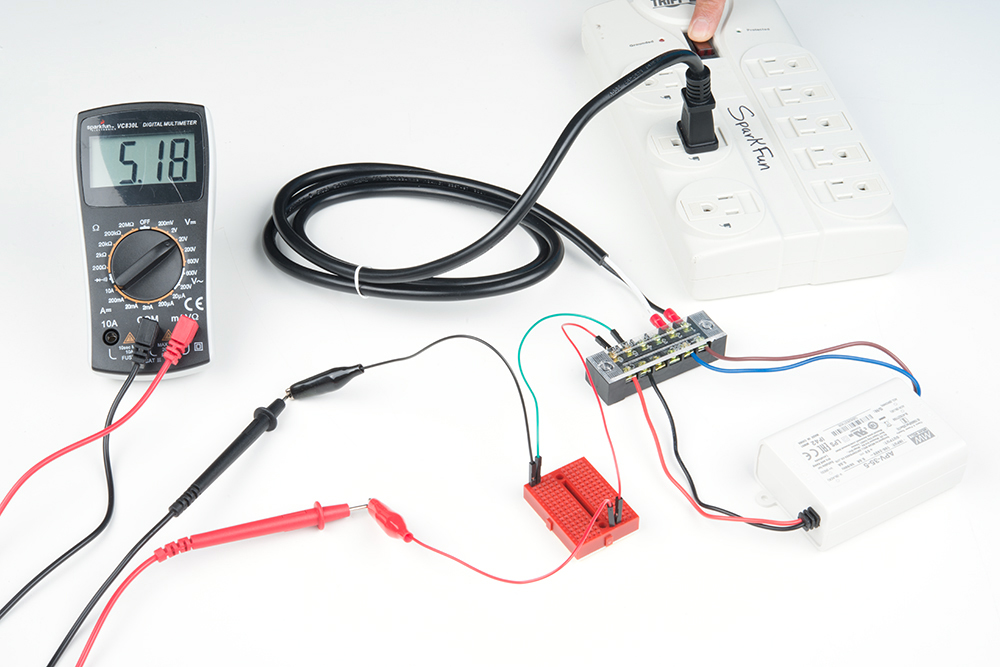
Let's test the power supply using a multimeter to see if we connected everything properly! To safely test, we will be using alligator clips, probes, and a breadboard to measure the output voltage to see if we get our expected voltage. If you are confident in your connections, you can also connect a multimeter's alligator clips directly to the output. Insert the two prong cable into a surge protector that is turned OFF. When ready, flip the switch on your surge protector to the ON position to provide power.
 |
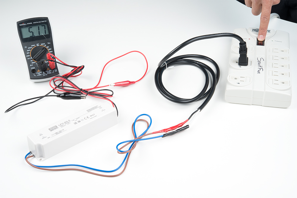 |
| Testing the APV-35 Series Output Voltage | Testing the LPV-60 Series Output Voltage |
If you are measuring a voltage that is close to your Mean Well power supply's output voltage rating, you are good to go!
Adding a Load
Remove power and connect your load to the output. In this case, I decided to power an addressable LED strip using an Arduino and custom built shield.
 |
 |
For safety and installation, make sure to add electrical tape around the exposed input voltage side and mount the electronics securely in an enclosure.
Power Large Loads and Daisy Chained LED Strips
When daisy chaining your addressable LED strips, there may be a voltage drop depending on the:
- amount of LEDs connected
- length of LED strip
- how bright the LEDs are set
- animation
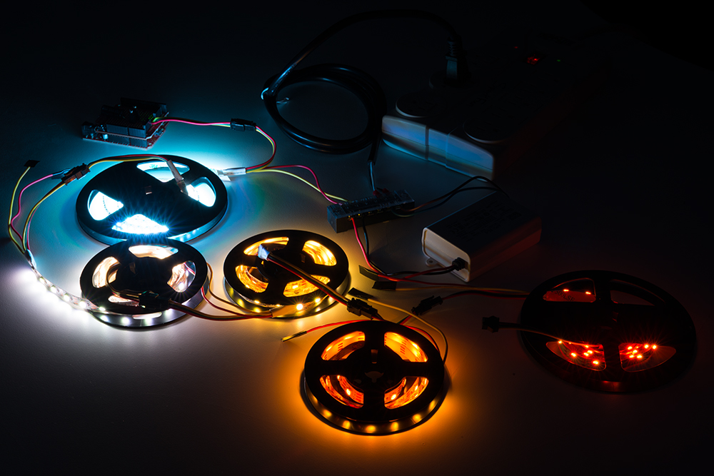
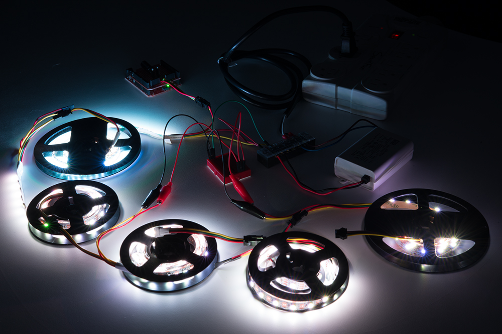
Below is an image of addressable LED strips daisy chained together and controlled by Arduino. The Arduino was programmed to turn on all the LEDs at full brightness using one 5V/25W power supply as an extreme case.
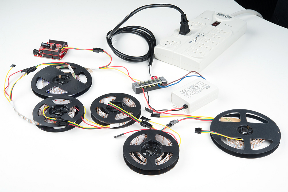
As you can see from the image below, the LEDs are not able to fully turn on after a certain length due to the voltage drop. This is due to the increased resistance as you move further away from the power supply. You may notice that not all the colors are turned on or the strip becomes dim. You can also check the voltage after each meter using a multimeter to see if there are any voltage drops if you are not able to visually see the voltage drops.
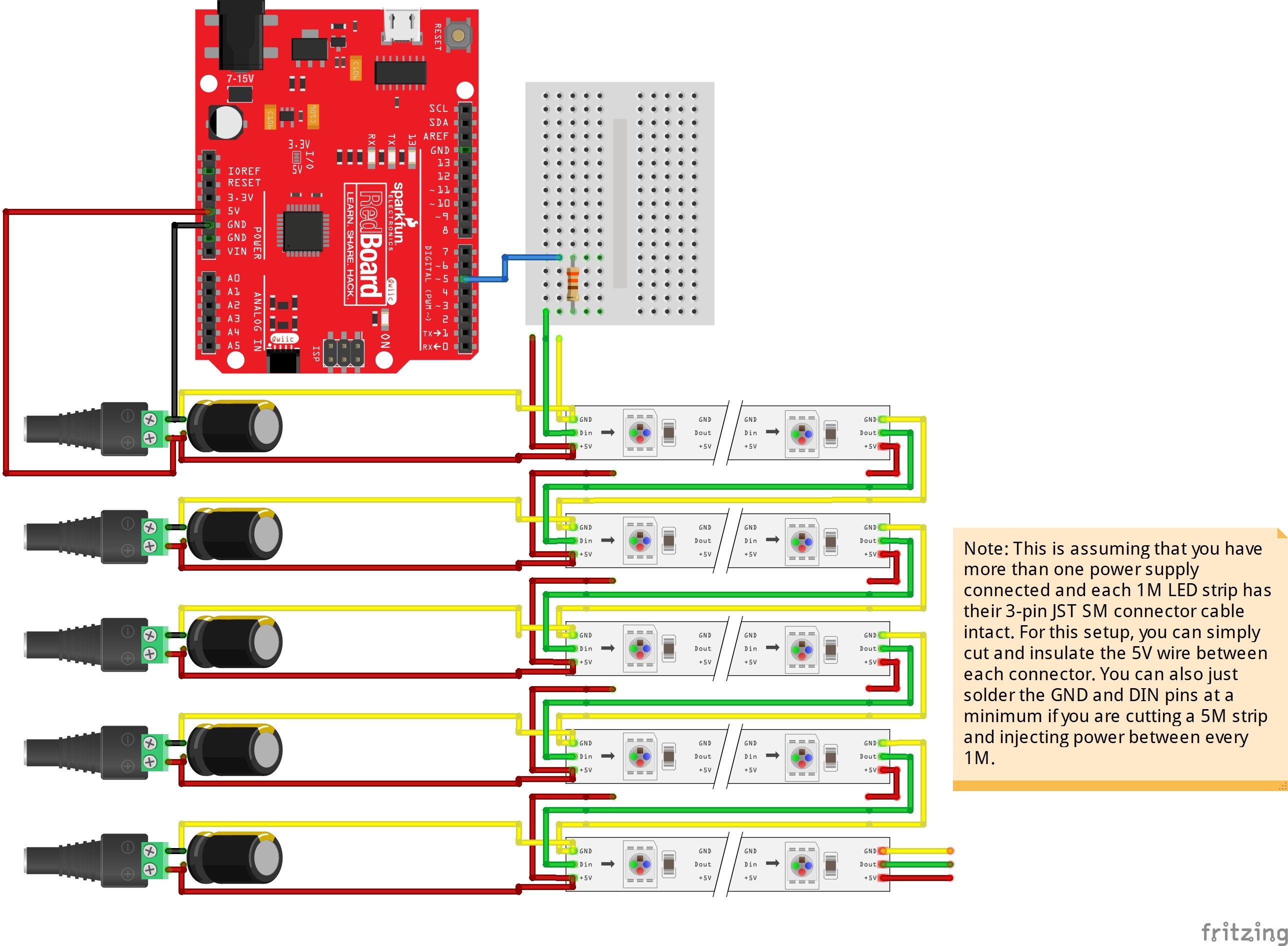
If you see voltage drops and the LED strip not properly turning on, you will need to connect the Mean Well's output between each LED strip's Vcc and GND after about 1, 2, or 5 meters. Your circuit may look similar to this setup if you daisy chain the LED strip and inject power between each cable.
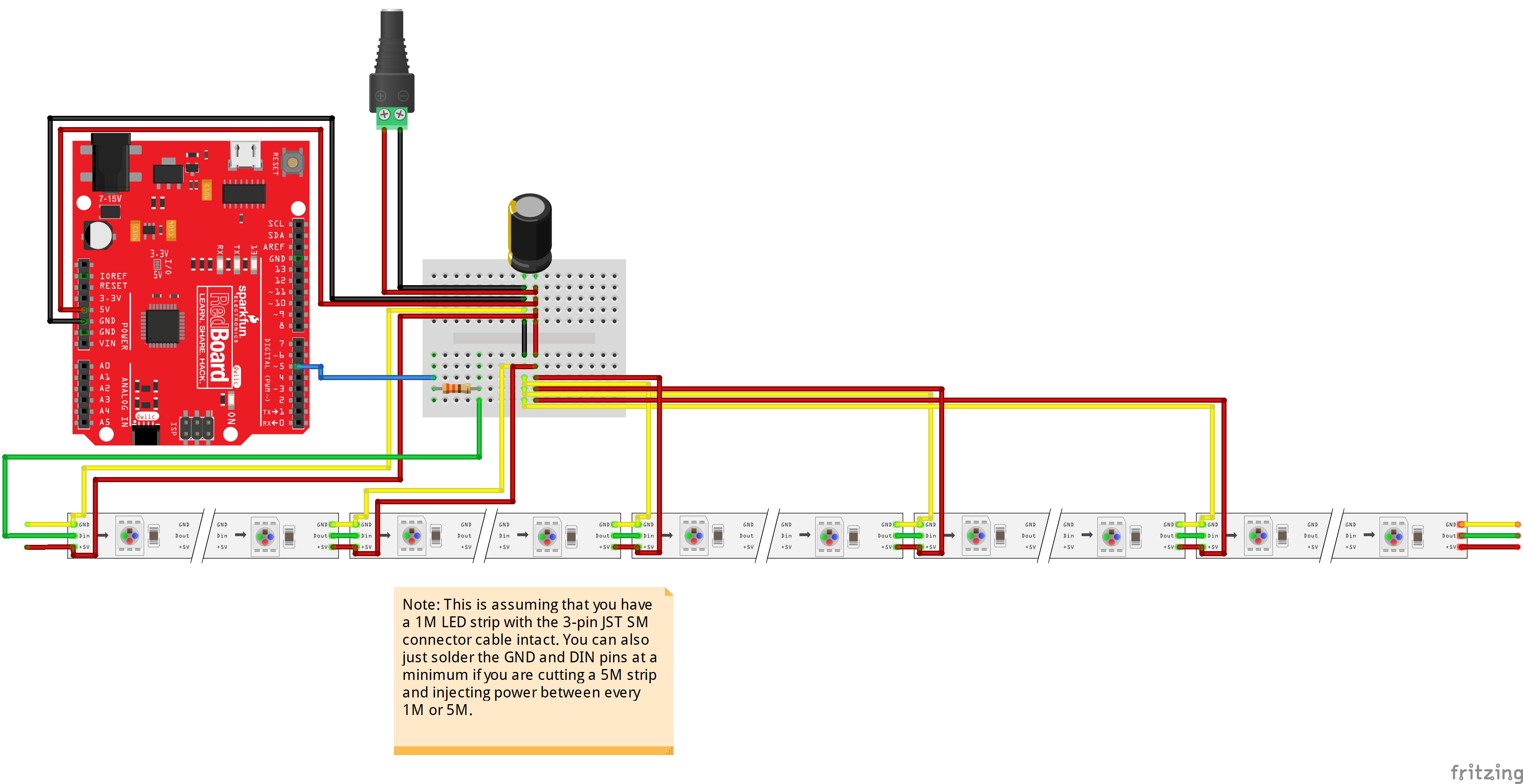
Once connected, your power supply should have a connection between each LED strip.
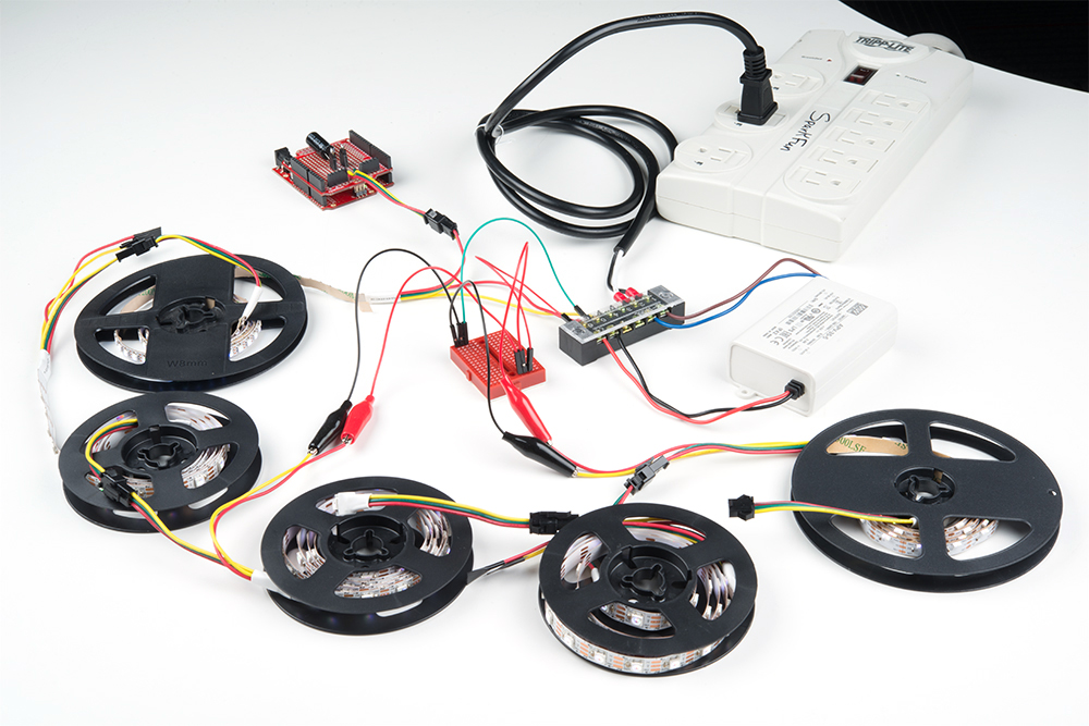
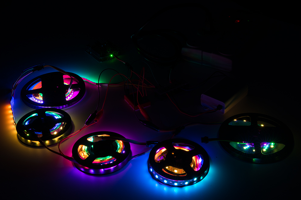
As you can see from the image below, the LEDs throughout the strip are able to fully turn on when connecting power between each LED strip.
Again, turning on all the LEDs at full brightness is an extreme case. You may be able get away with injecting power after more than a few meters if your setup uses a lower brightness setting and sequencing the LEDs.