How to Work with Jumper Pads and PCB Traces
Contributors:
 bboyho
What is a Jumper?
A jumper is an electrical connection designed to open or close a circuit between two or more points. Depending on the PCB, jumpers can be added into a design to change the board's default:
- Serial UART
- I2C Address
- SPI
- Voltage Level
- Pull-Up Resistor
- Mode
Jumper Pads
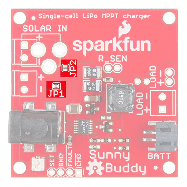
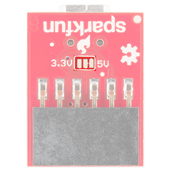
Below are a few examples of 1x2 and 1x3 jumper pads that are used with SparkFun boards. The spacing between pads are usually close together making it easy to add a solder.
 |
 |
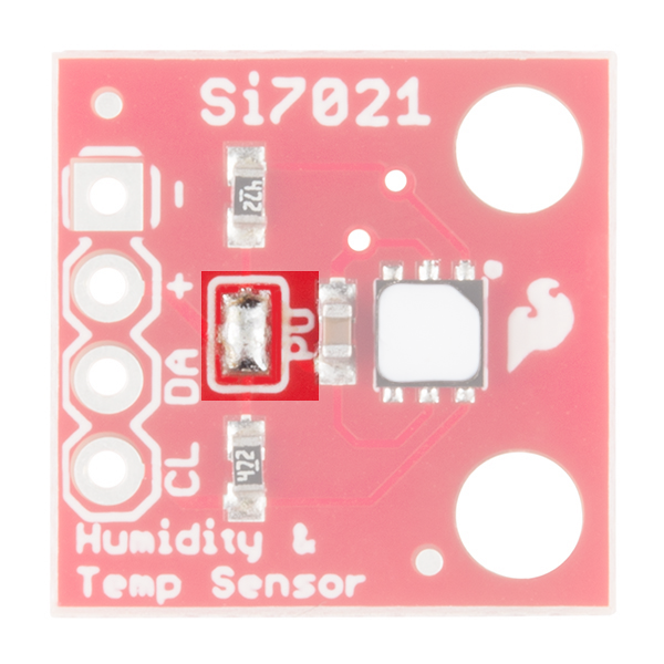 |
| Sunny Buddy w/ JP1 Closed Jumper and JP2 Open Jumper Pads | 5V FTDI w/ 1x3 Open and Closed Jumper Pads | Si7021 Humidity and Temperature Sensor w/ 1x3 Closed I2C Pull Up Jumper Pads |
Jumpers with Plated Through Hole Pads
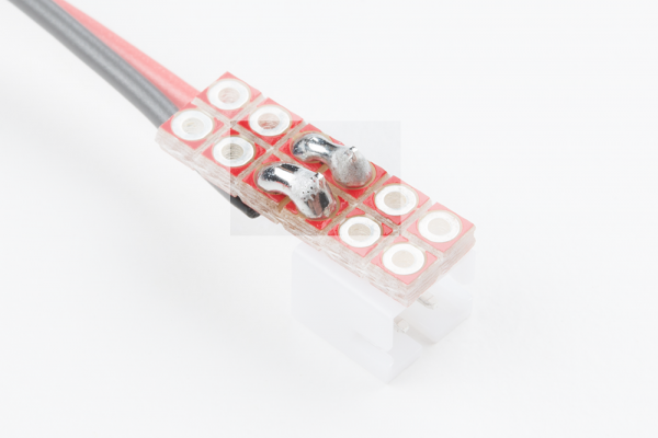
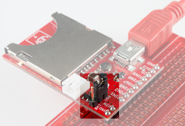
However, that may not always be the case for jumpers. Standard 0.1" pitched pins can have a wider gap or a development board may have a pin located in a different position. Additional solder, 2-pin jumper blocks, and jumper wires may be required to make a connection.
 |
 |
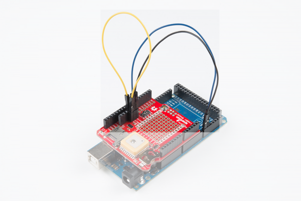 |
| Custom cable adapter using the snappable protoboard w/ solder jumpers between wires and connector. | Electric Imp Breakout w/ 2-Pin Jumper on Header | GPS Logger Shield w/ Software Serial Rerouted w/ Jumper Wires |