How to Work with Jumper Pads and PCB Traces
Contributors:
 bboyho
bboyho 
Cutting a Trace Between Jumper Pads
Locate the trace that you want to disconnect. The function of a jumper can vary depending on the board's design. For more information, try checking out the associated documentation for your board.
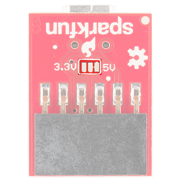
In this example, we will be looking at the 5V FTDI Basic Breakout to adjust the default voltage level from 5V to 3.3V. On the back of the board are three pads. If you look closely on the back of a 5V FTDI breakout, the center and right pads are connected together with a trace by default. On the 3.3V FTDI, the trace is connected to 3.3V by default.
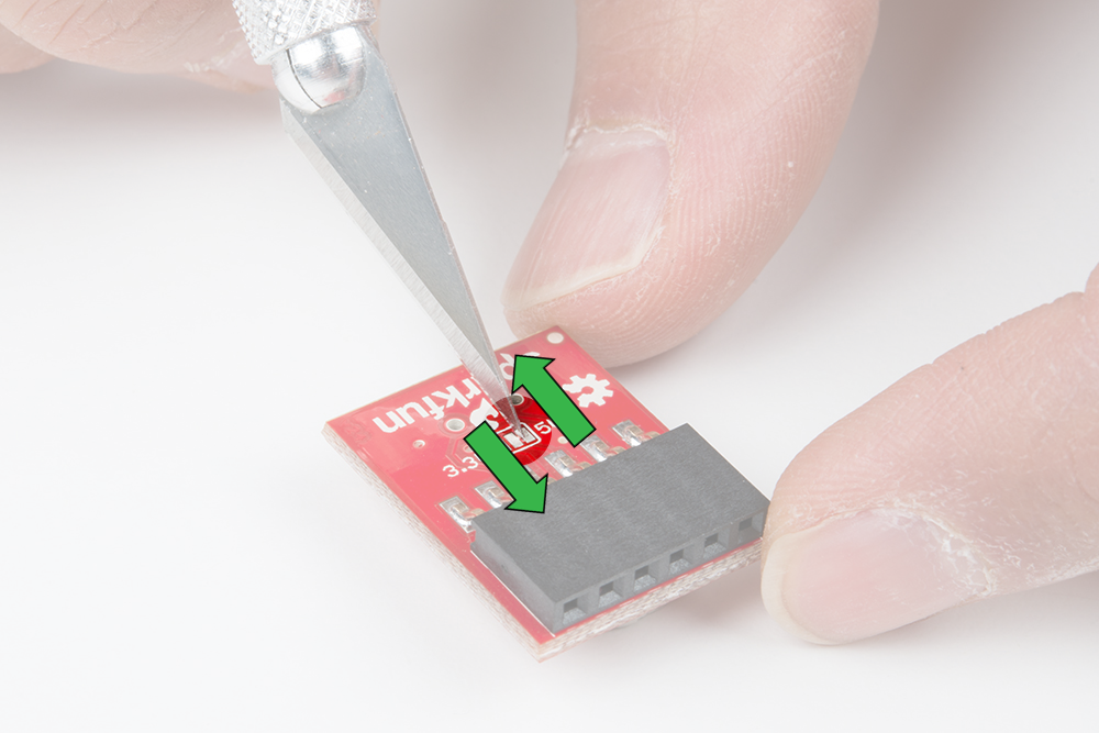
Using a hobby knife, carefully move the blade back and forth across the small trace to sever the connection under the red solder mask.
Caution! When cutting a trace, be careful not to cut any adjacent traces, pads, and your hand! The metal blade on a hobby knife is sharp so make sure to take your time.
There is a ceramic blade available as an alternative to reduce the risk of injury.
There is a ceramic blade available as an alternative to reduce the risk of injury.