Getting Started with the AutoDriver - v13
 SFUptownMaker
Multiple Board Example
There are some things to change to hook up multiple boards. This page will show you how to connect more than one AutoDriver to a RedBoard.
We're going to use the same sketch we used for the single board example. This sketch allows you to play music by controlling the step rate of your motor. The default song it plays is the first part of "Want You Gone" by Jonathon Coulton. I'm only including the main file and the support functions here; the notes.h and wantYouGone() function files are available on the board's GitHub page.
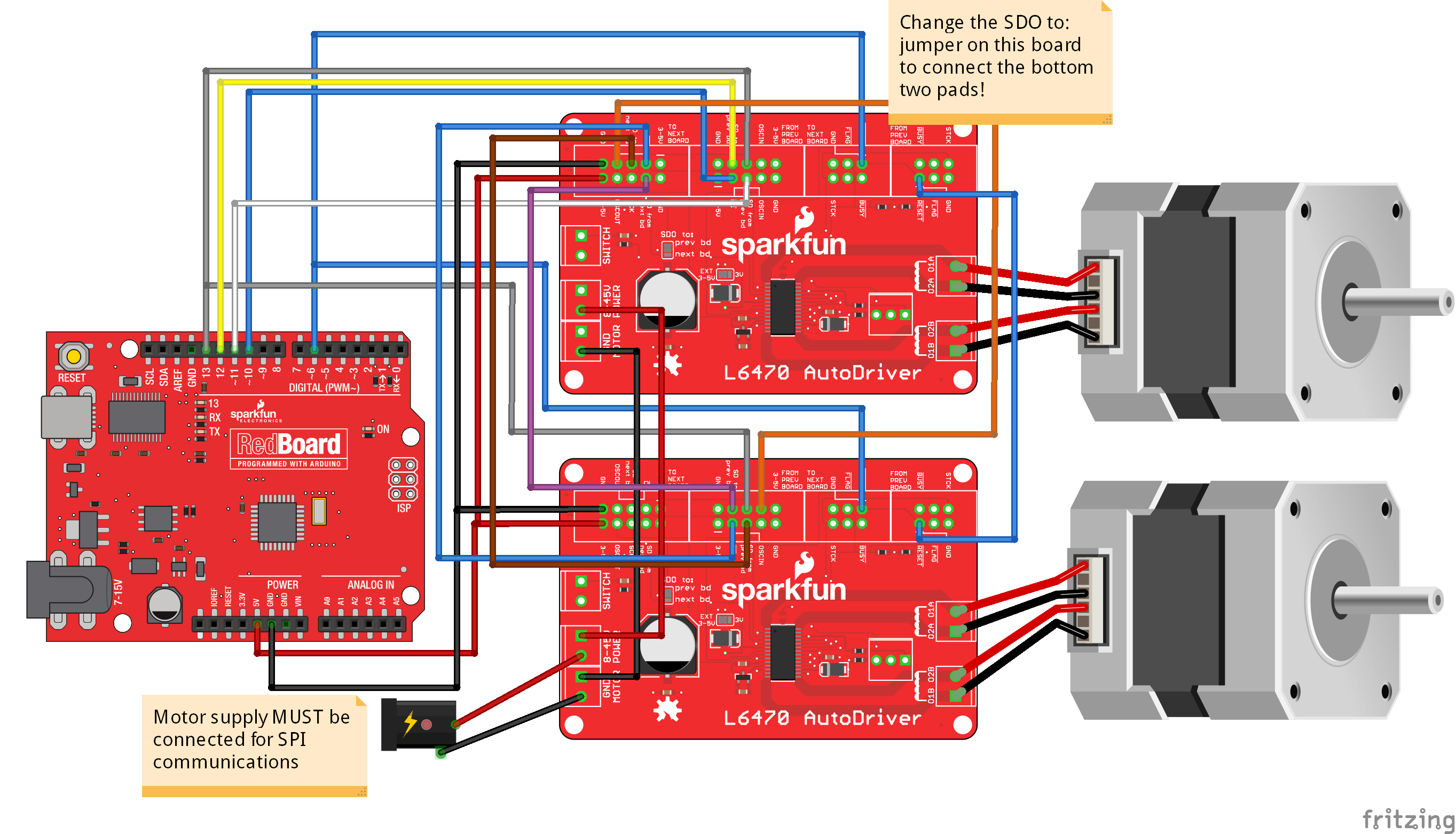
If you're using two boards, note the need to change the 'SDO to:' jumper setting to 'Next bd'! Failure to do so will result in failure of the sketch.
Because of the size and complexity of this sketch, it has been broken into several files. Please be sure you have all the files downloaded!
Setup() and Loop()
language:cpp
#include <SparkFunAutoDriver.h>
#include <SPI.h>
#include "SparkFunnotes.h"

// Test sketch for the L6470 AutoDriver library. This program instantiates three
//  AutoDriver boards and uses them to play Jonathon Coulton's "Want You Gone" from
//  the Portal 2 soundtrack. In a more general sense, it adds support for playing
//  music with stepper motors. Not all notes can be played, of course- at too high
//  a steps/sec rate, the motors will slip and dogs and cats will live together.


// Create our AutoDriver instances. The parameters are the position in the chain of
//  boards (with board 0 being located at the end of the chain, farthest from the
//  controlling processor), CS pin, and reset pin.
AutoDriver boardA(0, 10, 8);
AutoDriver boardB(1, 10, 8);

void setup()
{
  Serial.begin(9600);
  Serial.println("Hello world");
  // Start by setting up the SPI port and pins. The
  //  Autodriver library does not do this for you!
  pinMode(8, OUTPUT);
  pinMode(MOSI, OUTPUT);
  pinMode(MISO, INPUT);
  pinMode(13, OUTPUT);
  pinMode(10, OUTPUT);
  digitalWrite(10, HIGH);
  digitalWrite(8, LOW);       // This low/high is a reset of the L6470 chip on the
  digitalWrite(8, HIGH);      //  Autodriver board, and is a good thing to do at
                              //  the start of any Autodriver sketch, to be sure
                              //  you're starting the Autodriver from a known state.
  SPI.begin();
  SPI.setDataMode(SPI_MODE3);
  dSPINConfig();
}

// loop() waits for a character- any character- and then plays the song.
void loop()
{
  if (Serial.available() !=0)
  {
    Serial.read();
    Serial.println("Play it!");
    wantYouGone();
    Serial.println("Done playing!");
  }
}
In the main file, you can see that there's not much going on. We initiate two AutoDriver boards (as befits our hardware test setup described earlier), call a configuration function, initialize our SPI port and pins, then wait around for a user to request us to play the music.
Support Functions
// Support functions.

#define NOTE_DIVISOR 2  // My cheesy way of reducing the note frequencies to a range
                        //  that doesn't cause the motor to slip. I *could* rewrite
                        //  the wantYouGone() function to change the notes, but that
                        //  would be a lot of work.

int stepDir = 1;        // Direction flipping bit. Rather than all going one way,
                        //  they change directions. It looks cooler.

// To play a note, we start the motor spinning at the note's frequency in steps/s.
//  The run() function automagically calculates the appropriate value to feed to the
//  dSPIN part based on the desired steps/s.
void playNote(int note, int duration)
{
  if (stepDir == 1)  boardA.run(FWD, note/NOTE_DIVISOR);
  else               boardA.run(REV, note/NOTE_DIVISOR);
  if (stepDir == 1)  boardB.run(REV, note/NOTE_DIVISOR);
  else               boardB.run(FWD, note/NOTE_DIVISOR);
  delay(duration);
  stepDir*=-1;
  boardA.softStop();
  boardB.softStop();
  while (boardA.busyCheck());
}

// This is the configuration function for the two dSPIN parts. Read the inline
//  comments for more info.
void dSPINConfig(void)
{
  boardA.SPIPortConnect(&SPI);      // Before doing anything else, we need to
  boardB.SPIPortConnect(&SPI);      //  tell the objects which SPI port to use.
                                    //  Some devices may have more than one.

  boardA.configSyncPin(BUSY_PIN, 0);// BUSY pin low during operations;
                                    //  second paramter ignored.
  boardA.configStepMode(STEP_FS);   // 0 microsteps per step
  boardA.setMaxSpeed(10000);        // 10000 steps/s max
  boardA.setFullSpeed(10000);       // microstep below 10000 steps/s
  boardA.setAcc(10000);             // accelerate at 10000 steps/s/s
  boardA.setDec(10000);
  boardA.setSlewRate(SR_530V_us);   // Upping the edge speed increases torque.
  boardA.setOCThreshold(OC_750mA);  // OC threshold 750mA
  boardA.setPWMFreq(PWM_DIV_2, PWM_MUL_2); // 31.25kHz PWM freq
  boardA.setOCShutdown(OC_SD_DISABLE); // don't shutdown on OC
  boardA.setVoltageComp(VS_COMP_DISABLE); // don't compensate for motor V
  boardA.setSwitchMode(SW_USER);    // Switch is not hard stop
  boardA.setOscMode(EXT_16MHZ_OSCOUT_INVERT); // for boardA, we want 16MHz
                                    //  external osc, 16MHz out. boardB
                                    //  will be the same in all respects
                                    //  but this, as it will generate the
                                    //  clock.
  boardA.setAccKVAL(128);           // We'll tinker with these later, if needed.
  boardA.setDecKVAL(128);
  boardA.setRunKVAL(128);
  boardA.setHoldKVAL(32);           // This controls the holding current; keep it low.

  boardB.configSyncPin(BUSY_PIN, 0);// BUSY pin low during operations;
                                    //  second paramter ignored.
  boardB.configStepMode(STEP_FS);   // 0 microsteps per step
  boardB.setMaxSpeed(10000);        // 10000 steps/s max
  boardB.setFullSpeed(10000);       // microstep below 10000 steps/s
  boardB.setAcc(10000);             // accelerate at 10000 steps/s/s
  boardB.setDec(10000);
  boardB.setSlewRate(SR_530V_us);   // Upping the edge speed increases torque.
  boardB.setOCThreshold(OC_750mA);  // OC threshold 750mA
  boardB.setPWMFreq(PWM_DIV_2, PWM_MUL_2); // 31.25kHz PWM freq
  boardB.setOCShutdown(OC_SD_DISABLE); // don't shutdown on OC
  boardB.setVoltageComp(VS_COMP_DISABLE); // don't compensate for motor V
  boardB.setSwitchMode(SW_USER);    // Switch is not hard stop
  boardB.setOscMode(INT_16MHZ_OSCOUT_16MHZ); // for boardB, we want 16MHz
                                    //  internal osc, 16MHz out. boardA
                                    //  will be the same in all respects
                                    //  but this, as it will bring in and
                                    //  output the clock to keep them
                                    //  voth in phase.
  boardB.setAccKVAL(128);           // We'll tinker with these later, if needed.
  boardB.setDecKVAL(128);
  boardB.setRunKVAL(128);
  boardB.setHoldKVAL(32);           // This controls the holding current; keep it low.
}
The supportFunctions file has a good example of the settings used to configure the AutoDriver boards for this application, as well as a nice example of using the run() and softStop() functions to control the motion of the motor.
Other important items to note: we configure the oscillator on boardB (which, remember, we assigned to position 1) to generate a 16MHz signal on the oscillator out pin, and boardA to use the incoming signal and pass that signal to the next board (although. of course, there is no next board in this system). This will be the case in any chain of Autodriver boards: the highest numbered board should generate the clock, while all lower numbered boards use the input from the previous board and pass a clock signal to the next board. This ensures that all of the boards run at the same clock frequency and are in phase with one another.
Also take note of the SPIPortConnect() functions. You'll pass the same parameter to both of them, as they both use the same SPI port. The library takes care of all the under-the-hood stuff necessary to make sure the right board gets the right signals when you call a function later on.