First FPGA Project - Getting Fancy with PWM
Pulsing an LED
Armed with the PWM module from the component library, we can create a new module that will pulse an LED.
To pulse an LED we need to create values to feed to the PWM module that oscillate slowly between the minimum and maximum values. For simplicity, we are going to use a triangular waveform. You could get fancy and use something line a sine wave but this would be significantly more complicated.
By triangular waveform, I mean generating a counter value that linearly increases to the max value then linearly decreases to the minimum value before repeating.
So how can we efficiently create a triangular waveform? A free running counter will generate a saw-tooth waveform, meaning it linearly increases to the maximum then jumps to the minimum.
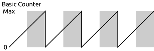
We can exploit this counter with a slight modification to create our waveform. First notice the gray shaded regions in the image above. These are where the MSB in the counter is 1.
If we remove the MSB from the counter we would see a waveform like this:

Notice the frequency has doubled and the max value is halved.
However, if we can flip the shaded regions we will have our triangular waveform.

This is great but how do we flip the value from the counter? One way is to simply subtract the value of the counter from max/2. However, there is a super efficient binary shortcut for this.
If instead of subtracting the value, we just invert the bits of the counter we get the same result. For example if we are counting from 0-7 the first three numbers are 000, 001, and 010. If we invert the bits that become 111, 110, 101, or 7, 6, 5. Simply by inverting each bit we can change the counter from counting up to counting down.
Putting this together into a module looks like this.
module pulse (
    input clk,  // clock
    input rst,  // reset
    output led  // output to led
  ) {

  .clk(clk) {
    .rst(rst) {
      pwm pwm(#WIDTH(8), #DIV(11));  // PWM component
      dff ctr[27];                   // counter
    }
  }

  always {
    led = pwm.pulse;    // connect the PWM output to the led

    ctr.d = ctr.q + 1;  // increment the counter

    pwm.update = 1;     // always update

    // connect the triangular waveform to the PWM module
    pwm.value = ctr.q[ctr.WIDTH-2-:pwm.value.WIDTH] ^ pwm.value.WIDTHx{ctr.q[ctr.WIDTH-1]};
  }
}
The line that does the inversion has some new syntax so let’s break that down.
First we need to select the bits of the counter that will be used for the PWM values. These are the eight MSBs of the counter excluding the first once since we are using that to know when to invert the value.
Every signal in Lucid has a constant WIDTH associated with it. This can be used to get how many bits make up the signal. So ctr.WIDTH is 27 in this case. We can use ctr.WIDTH-2 to get the second MSB.
We can then use pwm.value.WIDTH to get the width of the value input of pwm. Using the down-to syntax we can select pwm.value.WIDTH bits of ctr.q starting at ctr.WIDTH-2 and going down.
We are then doing a bitwise XOR using the ^ operator. This operator takes two signals of equal dimensions and XORs each of the corresponding bits together. We are using this since if you XOR a value with 0 it returns the value but if you XOR a value with 1 it inverts it.
We need to duplicate the MSB of our counter so that it is as many bits as pwm.value. To do this we use the duplication operator. This takes the format of num x{ value } where num is the number of times to duplicate value.
The space between num and x is optional but is typically written without it.
This line could’ve been written with numbers instead of using the WIDTH constants like this.
pwm.value = ctr.q[25-:8] ^ 8x{ctr.q[26]};
However, by using the WIDTH constants we can change the length of the counter or the pwm component without having to change anything else in our code.
We can use this module to drive an LED by adding it to our top-level module.
module au_top (
    input clk,              // 100MHz clock
    input rst_n,            // reset button (active low)
    output led [8],         // 8 user controllable LEDs
    input usb_rx,           // USB->Serial input
    output usb_tx           // USB->Serial output
  ) {

  sig rst;                  // reset signal

  .clk(clk) {
    // The reset conditioner is used to synchronize the reset signal to the FPGA
    // clock. This ensures the entire FPGA comes out of reset at the same time.
    reset_conditioner reset_cond;

    .rst(rst) {
      pulse pulse;
    }
  }

  always {
    reset_cond.in = ~rst_n; // input raw inverted reset signal
    rst = reset_cond.out;   // conditioned reset

    led = pulse.led;        // connect the LED to the pulser

    usb_tx = usb_rx;        // echo the serial data
  }
}
If you build and load this onto your board the first LED should now be slowly pulsing.