Detecting Colors with the SparkFun Tristimulus Color Sensor
Introduction
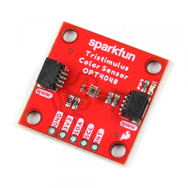
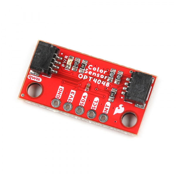
In this tutorial, we'll show you how to use the SparkFun Tristimulus Color Sensor - OPT4048DTSR (Qwiic) to detect and classify colors based on their CIE XYZ color space values. The sensor is capable of measuring the color intensity in the X, Y, and Z channels, which correspond to red, green, and blue components in a simplified form.
If you are looking for the full Hookup Guide for the SparkFun Tristimulus Color Sensor - OPT4048DTSR (Qwiic), click the button bellow. This guide only covers a simple project to get you started quickly, while the full Hookup Guide goes over every detail of the sensor.
Hardware Needed
To follow this experiment, you will need the following materials. While this is a simple project we wanted to make sure that you have everything you need to get started before we get to the code. For this simple project we chose the RedBoard Qwiic but you could choose from many of our development boards such as the Qwiic Pro Micro as well.
Software Setup
Installing the Required Libraries
- Install the SparkFun OPT4048 Library: Open the Arduino IDE and navigate to Sketch > Include Library > Manage Libraries. In the Library Manager, search for "OPT4048" and install the latest version from SparkFun.
Read Measurements with a Serial Monitor
Now that we've installed the Arduino library, it's time to upload our first sketch to make sure everything is working properly and you are able to read basic measurements with your Serial Monitor in the Arduino IDE.
For this example you will need the SparkFun Tristimulus Color Sensor - OPT4048DTSR (Qwiic), a SparkFun RedBoard Qwiic, a Qwiic Cable, and a USB Micro-B Cable.
Using the Qwiic system, assembling the hardware is simple. Connect the RedBoard to one of the SparkFun Tristimulus Color Sensor Qwiic ports using your Qwiic cables (please remember to insert this cable in the correct orientation). Then connect the RedBoard to your computer via the MicroUSB cable and voila! You're ready to rock!

Alternatively, you can copy and paste the code below into a shiny new Arduino sketch:
#include "SparkFun_OPT4048.h"  // Include the SparkFun OPT4048 library
#include <Wire.h>  // Include the Wire library for I2C communication

SparkFun_OPT4048 colorSensor;  // Create an instance of the OPT4048 color sensor

void setup() {
 Serial.begin(115200);  // Initialize serial communication at 115200 baud
 Serial.println("OPT4048 Color Sensing Example");  // Print a message to the serial monitor

 Wire.begin();  // Initialize the I2C bus

 if (!colorSensor.begin()) {  // Try to initialize the color sensor
   Serial.println("OPT4048 not detected - check wiring or I2C address!");
   while (1);  // Enter an infinite loop to halt the program
 }

 colorSensor.setBasicSetup();  // Apply basic setup configuration to the sensor

 Serial.println("Sensor initialized and ready!");  // Print a success message
}

void loop() {
  float x = colorSensor.getCIEx();  // Get the CIE X value from the sensor
  float y = colorSensor.getCIEy();  // Get the CIE Y value from the sensor
  float z = 1 - x - y;  // Approximate the CIE Z value (this is a simplification)

  Serial.print("CIEx: ");  // Print label for CIE X value
  Serial.print(x, 4);  // Print CIE X value with 4 decimal places
  Serial.print(" CIEy: ");  // Print label for CIE Y value
  Serial.print(y, 4);  // Print CIE Y value with 4 decimal places
  Serial.print(" CIEz: ");  // Print label for CIE Z value
  Serial.print(z, 4);  // Print approximated CIE Z value with 4 decimal places

  String detectedColor = classifyColor(x, y, z);  // Classify the color based on CIE values
  Serial.print(" Detected color: ");  // Print label for detected color
  Serial.println(detectedColor);  // Print the classified color

  delay(600);  // Wait for 600ms before the next reading (3 channels * 200ms conversion time)
}

String classifyColor(float x, float y, float z) {
  float total = x + y + z;  // Calculate the sum of x, y, and z
  float r = x / total;  // Calculate the relative red component
  float g = y / total;  // Calculate the relative green component
  float b = z / total;  // Calculate the relative blue component

  // The following if statements check the RGB ratios to classify the color
  if (r > 0.4 && g < 0.3 && b < 0.3) return "Red";
  if (r < 0.3 && g > 0.4 && b < 0.3) return "Green";
  if (r < 0.3 && g < 0.3 && b > 0.4) return "Blue";
  if (r > 0.3 && g > 0.3 && b < 0.3) return "Yellow";
  if (r > 0.3 && g < 0.3 && b > 0.3) return "Purple";
  if (r < 0.3 && g > 0.3 && b > 0.3) return "Cyan";
  if (r > 0.3 && g > 0.3 && b > 0.3) return "White";
  if (r < 0.1 && g < 0.1 && b < 0.1) return "Black";

  return "Unknown";  // If no color matches, return "Unknown"
}
Make sure you've selected the correct board and port in the Tools menu and then hit the upload button. Once the code has finished uploading, go ahead and open a Serial Monitor. Set the baud rate to 115200. You should see output like this:
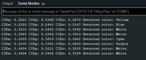
Interpreting the Results
- CIEx, CIEy, CIEz: These are the values from the CIE 1931 color space which represent the color's chromaticity.
- Detected Color: Based on the values, the code attempts to classify the color into a basic category like "Red," "Green," "Blue," etc.
The CIEx and CIEy values are going to fall somewhere between 0 and 1. Page 35 of the datasheet gives more detail on this, but generally speaking, you can map the predominant color of the space you're measuring using the following:
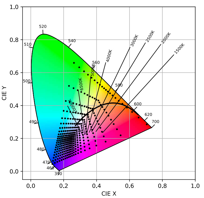
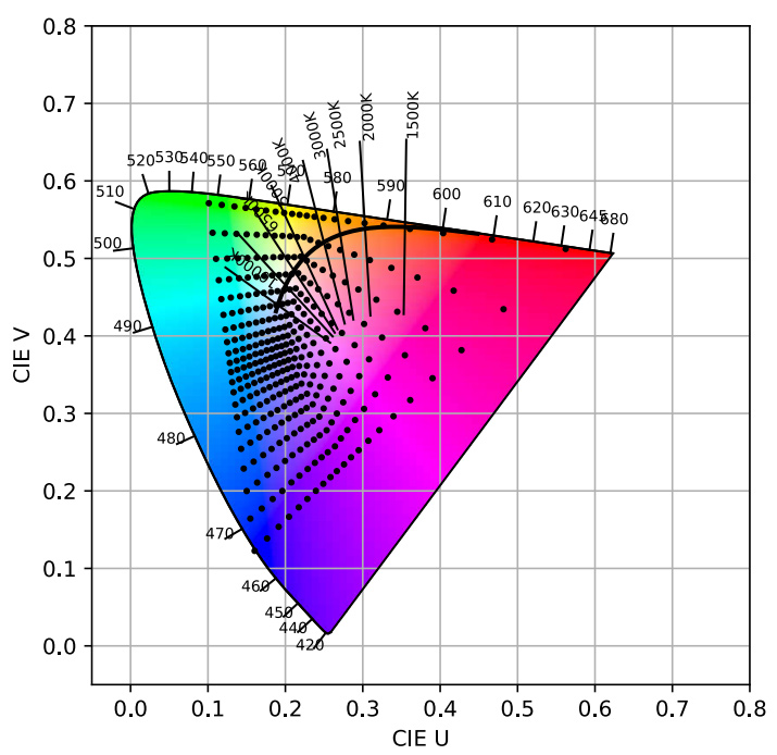
For more information on the CIE and CIY values, refer to the CIE 1931 Color Space Wiki Page.
If you see unexpected values or the sensor isn’t detected, double-check your wiring and ensure the sensor is properly connected to the I2C bus.
Conclusion
You've successfully set up the SparkFun Tristimulus Color Sensor to classify colors based on CIE XYZ values. This tutorial provides a foundation for more advanced color detection projects. You can now expand on this knowledge to create sophisticated color analysis systems or integrate the sensor into larger, more complex projects.