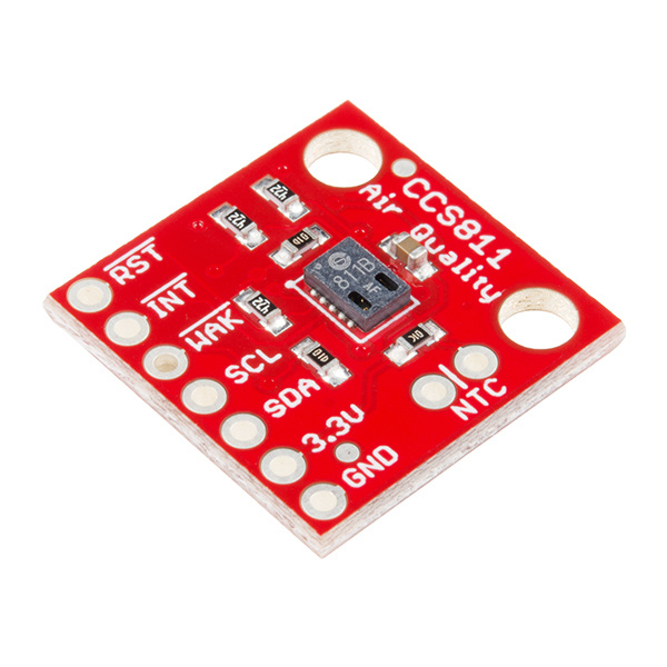
The CCS811 Air Quality Breakout is a digital gas sensor solution that senses a wide range of Total Volatile Organic Compounds (TVOCs), including equivalent carbon dioxide (eCO2) and metal oxide (MOX) levels. It is intended for indoor air quality monitoring in personal devices such as watches and phones, but we've put it on a breakout board so you can use it as a regular I2C device.
To follow along with this project tutorial, you will need the following materials:
If you aren't familiar with the following concepts, we recommend checking out these tutorials before continuing.
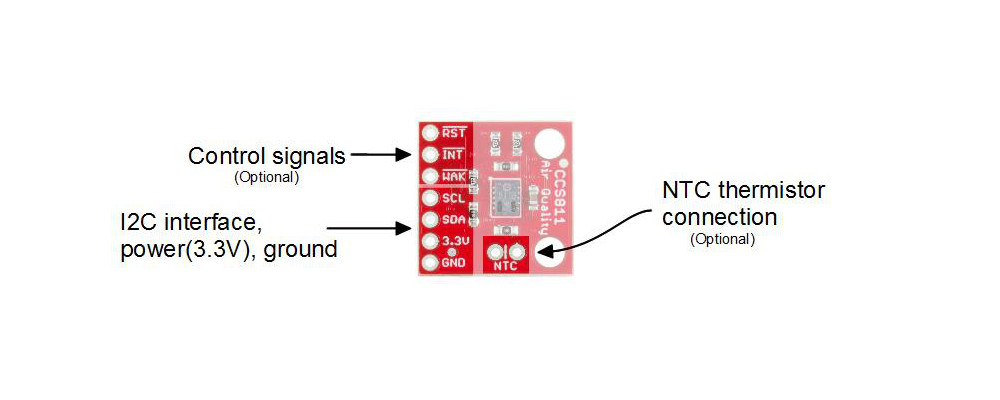
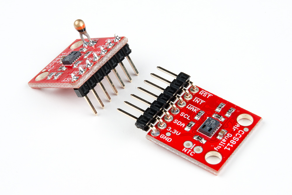
The CCS811 is supported by only a few passives, and so the breakout board is relatively simple. This section discusses the various pins on the board.

| Pin | Description | Direction |
|---|---|---|
| RST | Reset (active low) | In |
| INT | Interrupt (active low) | Out |
| WAK | Wake (active low) | In |
| SCL | Clock | In |
| SDA | Data | In |
| 3.3V | Power | In |
| GND | Ground | In |
| NTC (2 pins) | Negative thermal coefficient resistor | N/A |
The minimum required connections are power, ground SDA and SCL. Supply a regulated 3.3V between the board's 3.3V pin and ground terminals. The sensor consumes an average of 12mA of current.
The I2C bus has pull-up resistors enabled by default. If not desired, these can be removed by separating the "I2C PU" triple jumper on the bottom side with a hobby knife.
An I2C address can be either 0x5A or 0x5B. The "ADDR" jumper is connected with copper from the factory, corresponding to a default address of 0x5B. Close this jumper to use the address 0x5A.
Additionally, the three control lines RST, INT and WAK can be used to further the degree of control.
A thermistor can be used to determine the temperature of the CCS811's surroundings, which can be used to help compensate the readings. You'll need your own 10K NTC thermistor, such as our 10K Thermistor, soldered between the "NTC" pins. A thermistor is a nonpolarized device, so it can go in either way.
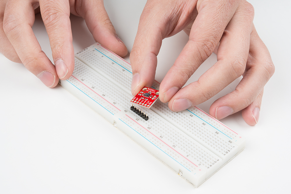
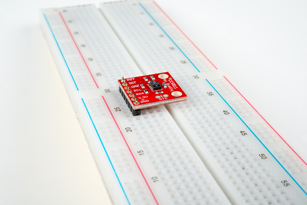
To prepare the sensor for the examples, attach seven pins from a Break Away Header to the through holes. Even though we only need the four I2C pins, we'll populate all of them for this guide in case we want to try them out.
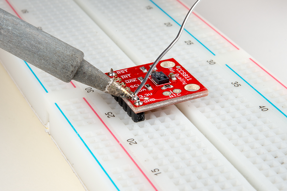
If you would like to use a thermistor to compensate for temperature, solder in a 10K Thermistor (Vishay part number NTCLE100E3103JB0).
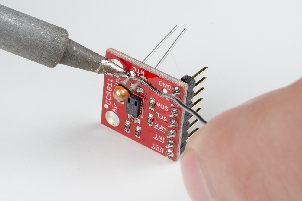
You're ready to start communicating with the CCS811! Here's an example with the NTC Thermistor populated, and one using right-angle headers instead.
To get the Arduino library, download from GitHub or use the Arduino Library Manager.
Download the GitHub repository
Visit the GitHub repository to download the most recent version of the library, or click the button below:
Use the Library Manager or install in the Arduino IDE
For help installing the library, check out our Installing an Arduino Library tutorial.
If you don't end up using the manager, you'll need to move the SparkFun_CCS811_Arduino_Library folder into a libraries folder within your Arduino sketchbook. If you downloaded the zip, you can remove "master" from the name, but it's not required.
The library is fairly normal to use compared with our other sensors. You'll have to include the library, create a sensor object in the global space, and then use functions of that object to begin and control the sensor. With this one, pass the I2C address to the object during construction.
To get the library included, and to take care of all the gritty compiler stuff, place the following at the beginning of the sketch before void setup()
language:c
#include <SparkFunCCS811.h>

#define CCS811_ADDR 0x5B //Default I2C Address
//#define CCS811_ADDR 0x5A //Alternate I2C Address

CCS811 myCCS811(CCS811_ADDR);
Now, functions of the object named myCCS811 can be called to set up and get data, while all the wire stuff is kept under the hood.
To make the sensor get ready during program boot, myCCS811.begin() must be called. Here's an example of the minimal usage of begin.
language:c
void setup()
{
    myCCS811.begin();
}
Then, in the main loop of the program, call sensor functions such as mySensor.readAlgorithmResults() to operate the sensor. The following snippet shows a simple check for data, to call on the sensor to calculate and get values, and to access those values. It doesn't do anything with the data, though! Check out the examples for fully functional code.
language:c
void loop()
{
  if (myCCS811.dataAvailable())
  {
    myCCS811.readAlgorithmResults();
    int tempCO2 = myCCS811.getCO2();
    int tempVOC = myCCS811.gettVOC();
  }
  else if (myCCS811.checkForStatusError())
  {
    while(1);
  }

  delay(1000); //Wait for next reading
}
The following functions exist for the CCS811 object.
Functions with scoped return type CCS811Core::status report an error state as defined in the literals section below. It is optional and can be used to determine success or failure of call.
bool begin( TwoWire = Wire ) --- Checks the ID register, checks for valid app data, starts the app, and establishes a drive mode.
CCS811Core::status beginWithStatus( TwoWire = Wire ) --- Checks the ID register, checks for valid app data, starts the app, and establishes a drive mode. Returns the status.
const char *CCS811::statusString(CCS811_Status_e stat) --- Returns a printable string of the status value.
CCS811Core::status readAlgorithmResults( void ) --- Call to cause the sensor to read its hardware and calculate TVOC and eCO2 levels.
bool checkForStatusError( void ) --- Returns true if there is an error pending. This checks the status register.
bool dataAvailable( void ) --- Returns true if a new sample is ready and hasn't been read.
bool appValid( void ) --- Returns true if there is a valid application within the internal CCS811 memory.
uint8_t getErrorRegister( void ) --- Returns the state of the ERROR_ID register.
uint16_t getBaseline( void ) --- Returns the baseline value.
CCS811Core::status setBaseline( uint16_t ) --- Apply a saved baseline to the CCS811.
CCS811Core::status enableInterrupts( void ) --- Enables the interrupt pin for data ready.
CCS811Core::status disableInterrupts( void ) --- Disables the interrupt pin.
CCS811Core::status setDriveMode( uint8_t mode ) --- Sets the drive mode (mode can be 0 through 4).
CCS811Core::status setEnvironmentalData( float relativeHumidity, float temperature ) --- Sets the environmental conditions for compensation.
uint16_t getTVOC( void ) --- Collect the last calculated TVOC value, in parts per billion (ppb).
uint16_t getCO2( void ) --- Collect the last calculated eC02 value, in parts per million (ppm).
Temperature compensation from an attached NTC thermistor is no longer supported on the CCS811 but these functions are still included in the library in case you are using an older version of this breakout (boards purchased in 2017).
void setRefResistance( float ) --- If you've changed the thermistor pull-up, call this to give the sensor the new resistor value. Otherwise, it will be 10000.
CCS811Core::status readNTC( void ) --- Cause the CCS811 to get and calculate a temperature from the thermistor input.
float getResistance( void ) --- Collect the last calculated resistance value of the NTC terminals.
float getTemperature( void ) --- Collect the last calculated temperature.
The CCS811 library defines the following special data type to deal with error states of functions. In most places the library can be used without paying attention to the function return types, but if they are needed, here are the values the data type status can hold:
language:c
// Return values
typedef enum
{
    CCS811_Stat_SUCCESS,
    CCS811_Stat_ID_ERROR,
    CCS811_Stat_I2C_ERROR,
    CCS811_Stat_INTERNAL_ERROR
    //...
} CCS811_Status_e;
To avoid the possibility of multiple libraries using the same status name, the enum is actually inside the scope of the CCS811 object, buried in the CCS811Core, which is the base class. Phew, don't worry about that too much; just place CCSCore:: before the status name when you want to use it, and use it like a regular enum (e.g., CCS811Core::CCS811_Status_e myLocalReturnStatus;). This just tells the compiler that the variable name is in a specific place. You'll also have to add the scope operator to the enum names.
Here's an example that shows how the status enum can be used:
language:c
CCS811Core::CCS811_Status_e returnCode = mySensor.beginCore();
Serial.print("beginCore exited with: ");
switch ( returnCode )
{
case CCS811Core::CCS811_Stat_SUCCESS:
  Serial.print("SUCCESS");
  break;
case CCS811Core::CCS811_Stat_ID_ERROR:
  Serial.print("ID_ERROR");
  break;
case CCS811Core::CCS811_Stat_I2C_ERROR:
  Serial.print("I2C_ERROR");
  break;
case CCS811Core::CCS811_Stat_INTERNAL_ERROR:
  Serial.print("INTERNAL_ERROR");
  break;
case CCS811Core::CCS811_Stat_GENERIC_ERROR:
  Serial.print("GENERIC_ERROR");
  break;
default:
  Serial.print("Unspecified error.");
}
The library also defines names for CCS811 registers, if you're using direct read and write functions. These are globally scoped and can be used anywhere.
language:c
//Register addresses
#define CSS811_STATUS 0x00
#define CSS811_MEAS_MODE 0x01
#define CSS811_ALG_RESULT_DATA 0x02
#define CSS811_RAW_DATA 0x03
#define CSS811_ENV_DATA 0x05
#define CSS811_NTC 0x06 (NTC compensation no longer supported)
#define CSS811_THRESHOLDS 0x10
#define CSS811_BASELINE 0x11
#define CSS811_HW_ID 0x20
#define CSS811_HW_VERSION 0x21
#define CSS811_FW_BOOT_VERSION 0x23
#define CSS811_FW_APP_VERSION 0x24
#define CSS811_ERROR_ID 0xE0
#define CSS811_APP_START 0xF4
#define CSS811_SW_RESET 0xFF
After you've got pins attached to your breakout board, the first example to use should be BasicReadings. Select it from examples or copy from below.
Connect the sensor as follows as a starting place for the examples.
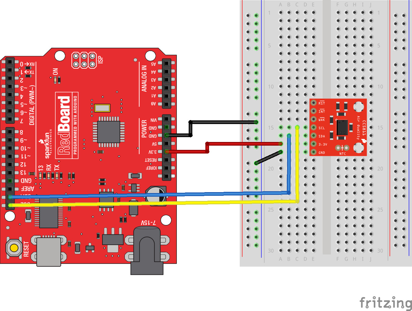
For this example, only 3.3V, GND, SDA and SCL are needed. The jumpers on the board are left in the default positions.
language:c
/******************************************************************************
  Read basic CO2 and TVOCs

  Marshall Taylor @ SparkFun Electronics
  Nathan Seidle @ SparkFun Electronics

  April 4, 2017

  https://github.com/sparkfun/CCS811_Air_Quality_Breakout
  https://github.com/sparkfun/SparkFun_CCS811_Arduino_Library

  Read the TVOC and CO2 values from the SparkFun CSS811 breakout board

  A new sensor requires at 48-burn in. Once burned in a sensor requires
  20 minutes of run in before readings are considered good.

  Hardware Connections (Breakoutboard to Arduino):
  3.3V to 3.3V pin
  GND to GND pin
  SDA to A4
  SCL to A5

******************************************************************************/
#include <Wire.h>

#include "SparkFunCCS811.h" //Click here to get the library: http://librarymanager/All#SparkFun_CCS811

#define CCS811_ADDR 0x5B //Default I2C Address
//#define CCS811_ADDR 0x5A //Alternate I2C Address

CCS811 mySensor(CCS811_ADDR);

void setup()
{
  Serial.begin(115200);
  Serial.println("CCS811 Basic Example");

  Wire.begin(); //Inialize I2C Hardware

  if (mySensor.begin() == false)
  {
    Serial.print("CCS811 error. Please check wiring. Freezing...");
    while (1)
      ;
  }
}

void loop()
{
  //Check to see if data is ready with .dataAvailable()
  if (mySensor.dataAvailable())
  {
    //If so, have the sensor read and calculate the results.
    //Get them later
    mySensor.readAlgorithmResults();

    Serial.print("CO2[");
    //Returns calculated CO2 reading
    Serial.print(mySensor.getCO2());
    Serial.print("] tVOC[");
    //Returns calculated TVOC reading
    Serial.print(mySensor.getTVOC());
    Serial.print("] millis[");
    //Display the time since program start
    Serial.print(millis());
    Serial.print("]");
    Serial.println();
  }

  delay(10); //Don't spam the I2C bus
}
At the beginning, an object is created in the global space CCS811 mySensor(CCS811_ADDR); and is constructed with the address as a parameter.
To get data from the sensor, mySensor.dataAvailable() is checked until a new reading is ready, mySensor.readAlgorithmResults(); is called to have the sensor process the reading, then mySensor.getCO2() and mySensor.getTVOC() are used to retrieve the calculated values for gas levels.
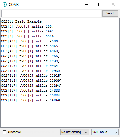
If everything is connected correctly, the serial window will report gas levels every second. Remember the sensor takes 20 minutes to properly warm up, so values reported will rise up in the early stages of operation!
Summary:
To get data from the CCS811, these minimum requirements must be met:
CCS811 object in the global space.begin() of your object (Return type monitoring optional).dataAvailable().readAlgorithmResults() to perform a measurement
.getCO2() to get the last equivalent CO2 reading (no I2C bus operation).getTVOC() to get the last TVOC reading (no I2C bus operation)The CCS811 has a couple extra control lines that are not part of the I2C bus, which can be utilized to improve the system. There's a pin to flag that data is ready, and a pin to make the sensor go to sleep.

To connect the interrupt line, connect it directly to an input pin. This is a 3.3V output from the sensor, so it's OK to drive the input logic of a 5V device from it. The example has nInt connected to pin 6.
To connect the wake stat line, use a voltage divider to divide the 5V coming from the Arduino down to something below 3.3V for the sensor. The example has nWake connected to pin 5 through a voltage divider made from two 4.7K resistors for a 2.5V output.
The example for these additional lines is called WakeAndInterrupt and is listed here:
language:c
/******************************************************************************
  WakeAndInterrupt.ino

  Marshall Taylor @ SparkFun Electronics

  April 4, 2017

  https://github.com/sparkfun/CCS811_Air_Quality_Breakout
  https://github.com/sparkfun/SparkFun_CCS811_Arduino_Library

  This example configures the nWAKE and nINT pins.
  The interrupt pin is configured to pull low when the data is
  ready to be collected.
  The wake pin is configured to enable the sensor during I2C communications

  Hardware Connections (Breakoutboard to Arduino):
  3.3V to 3.3V pin
  GND to GND pin
  SDA to A4
  SCL to A5
  NOT_INT to D6
  NOT_WAKE to D5 (For 5V arduinos, use resistor divider)
    D5---
         |
         R1 = 4.7K
         |
         --------NOT_WAKE
         |
         R2 = 4.7K
         |
        GND

  Resources:
  Uses Wire.h for i2c operation

  Development environment specifics:
  Arduino IDE 1.8.1

  This code is released under the [MIT License](http://opensource.org/licenses/MIT).

  Please review the LICENSE.md file included with this example. If you have any questions
  or concerns with licensing, please contact techsupport@sparkfun.com.

  Distributed as-is; no warranty is given.
******************************************************************************/
#include <SparkFunCCS811.h>

#define CCS811_ADDR 0x5B //Default I2C Address
//#define CCS811_ADDR 0x5A //Alternate I2C Address

#define PIN_NOT_WAKE 5
#define PIN_NOT_INT 6

CCS811 myCCS811(CCS811_ADDR);

//Global sensor object
//---------------------------------------------------------------
void setup()
{
  //Start the serial
  Serial.begin(9600);
  Serial.println();
  Serial.println("...");

  CCS811Core::status returnCode;

  //This begins the CCS811 sensor and prints error status of .begin()
  returnCode = myCCS811.begin();
  Serial.print("CCS811 begin exited with: ");
  printDriverError( returnCode );
  Serial.println();

  //This sets the mode to 60 second reads, and prints returned error status.
  returnCode = myCCS811.setDriveMode(2);
  Serial.print("Mode request exited with: ");
  printDriverError( returnCode );
  Serial.println();

  //Configure and enable the interrupt line,
  //then print error status
  pinMode(PIN_NOT_INT, INPUT_PULLUP);
  returnCode = myCCS811.enableInterrupts();
  Serial.print("Interrupt configuation exited with: ");
  printDriverError( returnCode );
  Serial.println();

  //Configure the wake line
  pinMode(PIN_NOT_WAKE, OUTPUT);
  digitalWrite(PIN_NOT_WAKE, 1); //Start asleep

}
//---------------------------------------------------------------
void loop()
{
  //Look for interrupt request from CCS811
  if (digitalRead(PIN_NOT_INT) == 0)
  {
    //Wake up the CCS811 logic engine
    digitalWrite(PIN_NOT_WAKE, 0);
    //Need to wait at least 50 us
    delay(1);
    //Interrupt signal caught, so cause the CCS811 to run its algorithm
    myCCS811.readAlgorithmResults(); //Calling this function updates the global tVOC and CO2 variables

    Serial.print("CO2[");
    Serial.print(myCCS811.getCO2());
    Serial.print("] tVOC[");
    Serial.print(myCCS811.getTVOC());
    Serial.print("] millis[");
    Serial.print(millis());
    Serial.print("]");
    Serial.println();

    //Now put the CCS811's logic engine to sleep
    digitalWrite(PIN_NOT_WAKE, 1);
    //Need to be asleep for at least 20 us
    delay(1);
  }
  delay(1); //cycle kinda fast
}


//printDriverError decodes the CCS811Core::status type and prints the
//type of error to the serial terminal.
//
//Save the return value of any function of type CCS811Core::status, then pass
//to this function to see what the output was.
void printDriverError( CCS811Core::status errorCode )
{
  switch ( errorCode )
  {
    case CCS811Core::SENSOR_SUCCESS:
      Serial.print("SUCCESS");
      break;
    case CCS811Core::SENSOR_ID_ERROR:
      Serial.print("ID_ERROR");
      break;
    case CCS811Core::SENSOR_I2C_ERROR:
      Serial.print("I2C_ERROR");
      break;
    case CCS811Core::SENSOR_INTERNAL_ERROR:
      Serial.print("INTERNAL_ERROR");
      break;
    case CCS811Core::SENSOR_GENERIC_ERROR:
      Serial.print("GENERIC_ERROR");
      break;
    default:
      Serial.print("Unspecified error.");
  }
}

//printSensorError gets, clears, then prints the errors
//saved within the error register.
void printSensorError()
{
  uint8_t error = myCCS811.getErrorRegister();

  if ( error == 0xFF ) //comm error
  {
    Serial.println("Failed to get ERROR_ID register.");
  }
  else
  {
    Serial.print("Error: ");
    if (error & 1 << 5) Serial.print("HeaterSupply");
    if (error & 1 << 4) Serial.print("HeaterFault");
    if (error & 1 << 3) Serial.print("MaxResistance");
    if (error & 1 << 2) Serial.print("MeasModeInvalid");
    if (error & 1 << 1) Serial.print("ReadRegInvalid");
    if (error & 1 << 0) Serial.print("MsgInvalid");
    Serial.println();
  }
}
Notice that this example doesn't poll dataAvailable() to check if data is ready; instead it reads the state of a digital input. When the input is low, data is ready in the sensor and readAlgorithmResults(), then .getCO2() and getTVOC() are used as normal.
The WAK pin can be used to control the logic engine on the CCS811 to save a bit of power. When the WAK pin is low (or disconnected), the I2C bus will respond to commands, but when the pin is high it will not. Tens of microseconds are required to wake or sleep, so in this example, commands are wrapped with a 1ms delay.
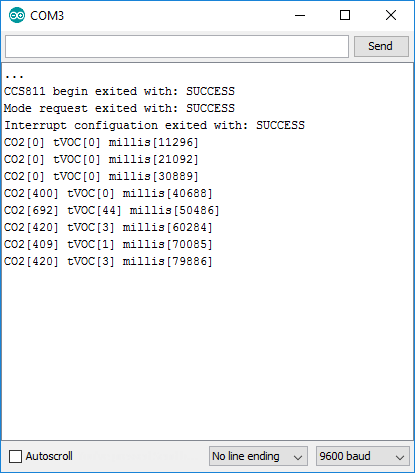
The terminal displays the calculation every 10 seconds. You can see that it take a few samples for the algorithm to spit out data, even at a slow rate of acquisition. Between the sampling, power is decreased as much as possible.
Summary:
To use WAK,
To use INT,
To have the CCS811 compensate for pressure and temperature conditions, obtain those metrics and pass to the sensor object with setEnvironmentalData.
The examples from the library show three different sources of data that can be used to calibrate the CCS811:
This guide only shows the example that uses randomized data, as it can be used without additional components yet still illustrate the effects of different climates.
From Arduino Library and Usage,
status_t setEnvironmentalData( float relativeHumidity, float temperature ) --- Sets the environmental conditions for compensation.
A starting place for working with the compensation is the setEnvironmentalReadings example. After the same configuration from the basic example, this sketch applies a random temperature and humidity, then takes 10 reads and repeats.
language:c
/******************************************************************************
setEnvironmentalReadings.ino

Marshall Taylor @ SparkFun Electronics

April 4, 2017

https://github.com/sparkfun/CCS811_Air_Quality_Breakout
https://github.com/sparkfun/SparkFun_CCS811_Arduino_Library

Hardware Connections (Breakoutboard to Arduino):
  3.3V to 3.3V pin
  GND to GND pin
  SDA to A4
  SCL to A5

Generates random temperature and humidity data, and uses it to compensate the CCS811.
This just demonstrates how the algorithm responds to various compensation points.
Use NTCCompensated or BME280Compensated for real-world examples.

Resources:
Uses Wire.h for i2c operation

Development environment specifics:
Arduino IDE 1.8.1

This code is released under the [MIT License](http://opensource.org/licenses/MIT).

Please review the LICENSE.md file included with this example. If you have any questions
or concerns with licensing, please contact techsupport@sparkfun.com.

Distributed as-is; no warranty is given.
******************************************************************************/
float temperatureVariable = 25.0; //in degrees C
float humidityVariable = 65.0; //in % relative

#include <Wire.h>
#include "SparkFunCCS811.h"

#define CCS811_ADDR 0x5B //Default I2C Address
//#define CCS811_ADDR 0x5A //Alternate I2C Address

CCS811 myCCS811(CCS811_ADDR);

void setup()
{
    Serial.begin(9600);
    Serial.println("CCS811 EnvironmentalReadings Example");

    //This begins the CCS811 sensor and prints error status of .begin()
    CCS811Core::status returnCode = myCCS811.begin();
    Serial.print("begin exited with: ");
    printDriverError( returnCode );
    Serial.println();

}

void loop()
{
    Serial.println();
    //Randomize the Temperature and Humidity
    humidityVariable = (float)random(0, 10000)/100; //0 to 100%
    temperatureVariable = (float)random(500, 7000)/100; // 5C to 70C
    Serial.println("New humidity and temperature:");
    Serial.print("  Humidity: ");
    Serial.print(humidityVariable, 2);
    Serial.println("% relative");
    Serial.print("  Temperature: ");
    Serial.print(temperatureVariable, 2);
    Serial.println(" degrees C");
    myCCS811.setEnvironmentalData(humidityVariable, temperatureVariable);

    Serial.println("Environmental data applied!");
    myCCS811.readAlgorithmResults(); //Dump a reading and wait
    delay(1000);
    //Print data points
    for( int i = 0; i < 10; i++)
    {
        if (myCCS811.dataAvailable())
        {
            //Calling readAlgorithmResults() function updates the global tVOC and CO2 variables
            myCCS811.readAlgorithmResults();

            Serial.print("CO2[");
            Serial.print(myCCS811.getCO2());
            Serial.print("] tVOC[");
            Serial.print(myCCS811.getTVOC());
            Serial.print("] millis[");
            Serial.print(millis());
            Serial.print("]");
            Serial.println();
        }
        else if (myCCS811.checkForStatusError())
        {
            //If the CCS811 found an internal error, print it.
            printSensorError();
        }
        delay(1000); //Wait for next reading
    }
}


//printDriverError decodes the CCS811Core::status type and prints the
//type of error to the serial terminal.
//
//Save the return value of any function of type CCS811Core::status, then pass
//to this function to see what the output was.
void printDriverError( CCS811Core::status errorCode )
{
    switch( errorCode )
    {
    case CCS811Core::SENSOR_SUCCESS:
        Serial.print("SUCCESS");
        break;
    case CCS811Core::SENSOR_ID_ERROR:
        Serial.print("ID_ERROR");
        break;
    case CCS811Core::SENSOR_I2C_ERROR:
        Serial.print("I2C_ERROR");
        break;
    case CCS811Core::SENSOR_INTERNAL_ERROR:
        Serial.print("INTERNAL_ERROR");
        break;
    case CCS811Core::SENSOR_GENERIC_ERROR:
        Serial.print("GENERIC_ERROR");
        break;
    default:
        Serial.print("Unspecified error.");
    }
}

//printSensorError gets, clears, then prints the errors
//saved within the error register.
void printSensorError()
{
    uint8_t error = myCCS811.getErrorRegister();

    if( error == 0xFF )//comm error
    {
        Serial.println("Failed to get ERROR_ID register.");
    }
    else
    {
        Serial.print("Error: ");
        if (error & 1 << 5) Serial.print("HeaterSupply");
        if (error & 1 << 4) Serial.print("HeaterFault");
        if (error & 1 << 3) Serial.print("MaxResistance");
        if (error & 1 << 2) Serial.print("MeasModeInvalid");
        if (error & 1 << 1) Serial.print("ReadRegInvalid");
        if (error & 1 << 0) Serial.print("MsgInvalid");
        Serial.println();
    }
}
If you have a BME280 sensor, they work great for getting the compensation parameters. Use the example BME280Compensated to see compensation using another sensor.
Connecting the two devices is as simple as putting them on the bus together.

View BME280Compensated.ino on github, or use the example from Arduino.
Alternately, an NTC resistor can be placed in the provided PTH terminals, and the example PTHCompensated can be used to see how the internal ADC is used to calibrate for temperature only.
There is one caveat to this method: no humidity data! Partially compensated is better than uncompensated, so punch in an average humidity for your area, or leave the example's default at 50 percent.
View NTCCompensated.ino on github, or use the example from Arduino.
Now that you've successfully got your CCS811 breakout up and running, and have scientifically proved which family member is the smelliest, here are some additional resources:
Also, the following examples are included with the library but not discussed. They may help you on your way!
Need some inspiration for your next project? Check out some of these sensor-related tutorials:
Or maybe check out our tests using the sensor at SparkFun!
learn.sparkfun.com | CC BY-SA 3.0 | SparkFun Electronics | Niwot, Colorado