Build an Auduino Step Sequencer
 Nick Poole
"You Spelled Arduino Wrong"
Kids these days, with their techno musics... am I right? Back in my day a synthesizer took up a whole room. Nowadays you can download one on your computerphone and be dubstepping by lunchtime.
Okay, I kind of am one of those kids. I can't get enough 'bleeps' and 'bloops'. So, when I came across the Auduino project, a grain synthesizer for Arduino, I was excited to put one together. And I did! And it was great! But that's not what this tutorial is about, because there are plenty of well documented builds on the Auduino site already. No, today we're going to take Auduino to the next level with the help of an Arduino Mega and a little code modification.
The original Auduino is a simple grain synthesizer: You twiddle the knobs and it makes a sound. Don't get me wrong, you can spend hours doing that... there's just not much composition in it. We'll be turning this basic synthesizer into a step sequencer, allowing us to program 8 different sounds and play them in a repeated loop.
Before we start changing things up, let's make sure we understand what Auduino looks like when you download it.
Suggested Reading
This project builds upon a few other concepts and skills. Feel free to read up on any with which you are unfamiliar.
Parts I Used
Understanding the Framework
The beauty of Auduino is that it's elegantly written. There are no libraries to install, just a single sketch to download and unzip into its own folder. Heck, the whole thing compiles to only about 2KB! Instead of dumping that code out here and sifting through it, I'll try to abbreviate and give you sort of a wireframe view of how it works:
The top of the sketch is mainly used as a space for declaring global variables where the oscillator parameters will be stored. There's also a section that defines hardware dependent functions like PWM_INTERRUPT based on what hardware is detected by the compiler. After that, there are a few frequency mapping tables for the grain repetition frequency, the sketch uses a pentatonic mapping by default, which is nice because it makes it impossible to play a really sour note.
Next, we happen upon a procedure called AudioOn() which sets up the PWM timer. This is another hardware dependent setting.
Finally, we get to the familiar setup() routine, which is refreshingly straight-forward. All that happens here is that we put the PWM output (the audio out pin) in OUTPUT mode. Then the audioOn() procedure gets the PWM timer rolling, and we finish up by setting up our status LED.
The main loop of the sketch reads the analog inputs that are used to control the synth parameters. The controller will basically read and re-read the analog inputs until a preset timer overflows, and then the SIGNAL(PWM_INTERRUPT) procedure will launch. That's where all of the action happens.
SIGNAL is a procedure that runs every time that the timer defined by PWM_INTERRUPT overflows. This ensures that the synthesizer runs at a set frequency, regardless of what's happening in the main loop. We'll use this to our advantage, when we make our modifications later. If you want to understand exactly how this routine creates the wild and wacky sounds you're hearing, then you'll need to poke around the Auduino Wiki; algorithmic synthesis can be a challenging concept.
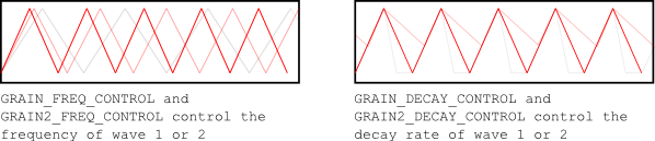
In short, the sound is comprised of two triangle waves which are calculated based on the analog inputs. There are two analog inputs for each wave: one controls the frequency of the wave, and the other controls the decay.
These waves have the same static duration, and the combined waves over the length of that duration comprise what's called a grain.
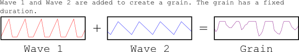
Finally there's an analog input that controls the frequency at which this "grain" is repeated. The result is a mashup of the repetition frequency and the original grain.
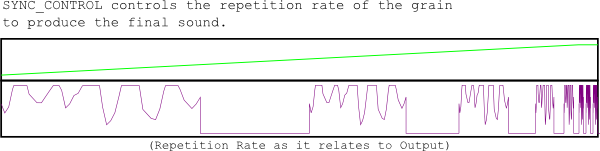
The Auduino Wiki claims that it sounds a lot like a single oscillator with a pair of resonating bandpass filters, and it does indeed. In fact, you could be forgiven for thinking of the frequency and decay knobs as frequency and resonance ('Q') knobs. However, because the effect is achieved through granular synthesis, some really interesting stuff happens when frequencies approach the extreme limits of the timer.
To accomplish this musical magic, the SIGNAL() procedure performs a handful of fancy bitwise operations, which make the code difficult to understand at first glance but make it very fast. So fast, in fact, that there's plenty of room in between timer overflows for us to add a few features...
Modifying the Framework
Now that we have a basic understanding of how the standard Auduino sketch works, we can start adding some of our own procedures to the main loop. First let's lay out what it is that we're trying to accomplish.
This tutorial is all about building a "step sequencer," a synthesizer that will hold a number of different parameters and play them back in sequence. This means that, along with more analog inputs, we'll also need:
- Global Variables to hold all of the parameters for each step
- Controls for selecting and changing steps in the sequence (step editor)
- A Mechanism for advancing through all steps in the sequence at a set rate (playback)
- A Control for changing the step rate (tempo)
I threw in another cool feature: the ability to shift the parameters on all steps in the sequence at once. That way I can setup a sequence and run it while I sweep the filters around. Also, I can pitch-shift the entire sequence.
You can download the complete altered sketch here, if you're not into copy/paste.
Let's go through the new code and figure out where all of these changes are gonna live:
First, we'll need to establish a heaping handful of global variables...
language:c
int tempo = 100000;
int pattern = 0;
int counter = 0;

int a1 = 0; int a2 = 0; int a3 = 0; int a4 = 0; int a5 = 0;
int b1 = 0; int b2 = 0; int b3 = 0; int b4 = 0; int b5 = 0;
int c1 = 0; int c2 = 0; int c3 = 0; int c4 = 0; int c5 = 0;
int d1 = 0; int d2 = 0; int d3 = 0; int d4 = 0; int d5 = 0;
int e1 = 0; int e2 = 0; int e3 = 0; int e4 = 0; int e5 = 0;
int f1 = 0; int f2 = 0; int f3 = 0; int f4 = 0; int f5 = 0;
int g1 = 0; int g2 = 0; int g3 = 0; int g4 = 0; int g5 = 0;
int h1 = 0; int h2 = 0; int h3 = 0; int h4 = 0; int h5 = 0;

int live_sync_phase = 0;
int live_grain_phase = 0;
int live_grain_decay = 0;
int live_grain2_phase = 0;
int live_grain2_decay = 0;
The "tempo" variable will dictate how many loop cycles can elapse before we move to the next step in the sequence. The user will access this variable directly using an analog input. Next, we setup a variable called "pattern," which would be better thought of as "step." It controls which step in the 8-step sequence we're currently playing. We also need to create a counter, which will keep track of how many loop cycles we've executed. This will be compared to "tempo" during each iteration, so we know when to advance one step in the sequence.
The big block of alphanumerically labeled integer variables will be used to store the five grain synthesizer parameters (1-5) for each of the eight steps (a-h). This could be accomplished using a table as well. This way, it's obvious to the beginner what's going on later, because we won't be calling stuff from tables.
Finally, there is a set of five variables that contain what I call the "live" parameters -- the adjustments that are made to the entire 8-step sequence during play.
Now that we've created all of our global variables, we can start configuring our hardware. I added these chunks to the setup procedure:
language:c
  pinMode(39, OUTPUT); digitalWrite(39, LOW);
  pinMode(41, OUTPUT); digitalWrite(41, LOW);
  pinMode(43, OUTPUT); digitalWrite(43, LOW);
  pinMode(45, OUTPUT); digitalWrite(45, LOW);
  pinMode(47, OUTPUT); digitalWrite(47, LOW);
  pinMode(49, OUTPUT); digitalWrite(49, LOW);
  pinMode(51, OUTPUT); digitalWrite(51, LOW);
  pinMode(53, OUTPUT); digitalWrite(53, LOW);

  pinMode(24, INPUT); digitalWrite(24, HIGH);
  pinMode(26, INPUT); digitalWrite(26, HIGH);
  pinMode(28, INPUT); digitalWrite(28, HIGH);
  pinMode(30, INPUT); digitalWrite(30, HIGH);
  pinMode(32, INPUT); digitalWrite(32, HIGH);
  pinMode(34, INPUT); digitalWrite(34, HIGH);
  pinMode(36, INPUT); digitalWrite(36, HIGH);
  pinMode(38, INPUT); digitalWrite(38, HIGH);
The first eight lines correspond to the eight status LEDs that indicate the user's position in the sequence. The second set of eight are the eight buttons used to select a step in the sequence for editing. All of the LEDs are declared as outputs and default to the LOW position. Whereas, all of the buttons are declared as inputs, and the internal pull-up resistors are set for each.
And now, the main loop. I'll explain as much as I can in the comments:
language:c
void loop() {


  counter++;

/* Most of the time, the main loop will just advance the counter while we continue generating noise. Each iteration, we check the counter against our "tempo" parameter to find out if it's time yet to jump to the next step. */

  if(counter>tempo){ //If it's time to advance to the next step:


//Housecleaning: Just a few things to get out of the way since the counter is "full"

  counter=0; //Reset the counter variable
  if(pattern==8){pattern=0;} //Make sure we're not about to go to imaginary step 9.
  pattern++; //Let all of the following code know that we're setting up for the next step
  //Turn off all of the step indicator lights in preparation for lighting the correct one.
  digitalWrite(39, LOW);digitalWrite(41, LOW);digitalWrite(43, LOW);digitalWrite(45, LOW);
  digitalWrite(47, LOW);digitalWrite(49, LOW);digitalWrite(51, LOW);digitalWrite(53, LOW);


 //Live Tweaks: Read the analog inputs associated with each "live" parameter.

  live_sync_phase = map(analogRead(14),0,1023,-500,500);
  live_grain_phase = map(analogRead(10),0,1023,-200,200);
  live_grain_decay = map(analogRead(9),0,1023,-20,20);
  live_grain2_phase = map(analogRead(8),0,1023,-200,200);
  live_grain2_decay = map(analogRead(11),0,1023,-50,50);


//Tempo Control: Read the analog inputs associated with the "tempo" parameter.
  tempo = map(analogRead(15),0,1023,1000,32000);


//Grab the parameters for the step that we're now in. We'll use a series of case
//statements switched on the "pattern" variable that we incremented earlier.

/* In each of the case routines below you'll notice that we're addressing
each of the existing Auduino parameters and making them equal to the stored
parameter plus the associated "live" parameter. */

  switch(pattern){

    case 1:
    syncPhaseInc = a1 + live_sync_phase; grainPhaseInc = a2 + live_grain_phase; grainDecay = a3 + live_grain_decay; grain2PhaseInc = a4 + live_grain2_phase; grain2Decay = a5 + live_grain2_decay; digitalWrite(53, HIGH); break;
    case 2:
    syncPhaseInc = b1 + live_sync_phase; grainPhaseInc = b2 + live_grain_phase; grainDecay = b3 + live_grain_decay; grain2PhaseInc = b4 + live_grain2_phase; grain2Decay = b5 + live_grain2_decay; digitalWrite(51, HIGH); break;
    case 3:
    syncPhaseInc = c1 + live_sync_phase; grainPhaseInc = c2 + live_grain_phase; grainDecay = c3 + live_grain_decay; grain2PhaseInc = c4 + live_grain2_phase; grain2Decay = c5 + live_grain2_decay; digitalWrite(49, HIGH); break;
    case 4:
    syncPhaseInc = d1 + live_sync_phase; grainPhaseInc = d2 + live_grain_phase; grainDecay = d3 + live_grain_decay; grain2PhaseInc = d4 + live_grain2_phase; grain2Decay = d5 + live_grain2_decay; digitalWrite(47, HIGH); break;
    case 5:
    syncPhaseInc = e1 + live_sync_phase; grainPhaseInc = e2 + live_grain_phase; grainDecay = e3 + live_grain_decay; grain2PhaseInc = e4 + live_grain2_phase; grain2Decay = e5 + live_grain2_decay; digitalWrite(45, HIGH); break;
    case 6:
    syncPhaseInc = f1 + live_sync_phase; grainPhaseInc = f2 + live_grain_phase; grainDecay = f3 + live_grain_decay; grain2PhaseInc = f4 + live_grain2_phase; grain2Decay = f5 + live_grain2_decay; digitalWrite(43, HIGH); break;
    case 7:
    syncPhaseInc = g1 + live_sync_phase; grainPhaseInc = g2 + live_grain_phase; grainDecay = g3 + live_grain_decay; grain2PhaseInc = g4 + live_grain2_phase; grain2Decay = g5 + live_grain2_decay; digitalWrite(41, HIGH); break;
    case 8:
    syncPhaseInc = h1 + live_sync_phase; grainPhaseInc = h2 + live_grain_phase; grainDecay = h3 + live_grain_decay; grain2PhaseInc = h4 + live_grain2_phase; grain2Decay = h5 + live_grain2_decay; digitalWrite(39, HIGH); break;
  }

//Check to see if the user is trying to change the step parameters.
//This series of statements simply check for a button press from each of
//the step buttons and call a function to change the indicated step.

    if(digitalRead(24)==LOW){changeStep(1);}
    if(digitalRead(26)==LOW){changeStep(2);}
    if(digitalRead(28)==LOW){changeStep(3);}
    if(digitalRead(30)==LOW){changeStep(4);}
    if(digitalRead(32)==LOW){changeStep(5);}
    if(digitalRead(34)==LOW){changeStep(6);}
    if(digitalRead(38)==LOW){changeStep(7);}
    if(digitalRead(36)==LOW){changeStep(8);}
}}
Hopefully that wasn't too confusing. Basically the main loop just counts up until the counter hits the "tempo" value, then it pops over to the next step in the sequence, loading up the parameters for that step and being sure to reset to step 1 when it passes step 8. Finally, it checks for user input from the step change buttons. If there's a button press (meaning that the user wants to change the step for that button) we call a function to alter the appropriate parameters and pass it the number of the step that we want to change:
language:c
void changeStep(int step_num){

/* The first thing we do is to turn off all indicator lights so that we can properly indicate which step we're currently editing. */

  digitalWrite(39, LOW);digitalWrite(41, LOW);digitalWrite(43, LOW);digitalWrite(45, LOW);
  digitalWrite(47, LOW);digitalWrite(49, LOW);digitalWrite(51, LOW);digitalWrite(53, LOW);

// Then indicate the appropriate step.

    switch(step_num){

    case 1:
    digitalWrite(53, HIGH); break;
    case 2:
    digitalWrite(51, HIGH); break;
    case 3:
    digitalWrite(49, HIGH); break;
    case 4:
    digitalWrite(47, HIGH); break;
    case 5:
    digitalWrite(45, HIGH); break;
    case 6:
    digitalWrite(43, HIGH); break;
    case 7:
    digitalWrite(41, HIGH); break;
    case 8:
    digitalWrite(39, HIGH); break;
  }


/* This next chunk of code is fairly similar to the unaltered Auduino sketch. This allows
us to continue updating the synth parameters to the user input. That way, you can dial in
the sound of a particular step. The while-loop traps the program flow here until the user
pushes button 1. As the code currently stands, "live" parameters aren't applied while in
the step editor but you could easily add the live parameters below. */


while(1){

  counter++;
  if(counter>tempo){

  counter=0;
  syncPhaseInc = mapPentatonic(analogRead(SYNC_CONTROL));

  grainPhaseInc  = mapPhaseInc(analogRead(GRAIN_FREQ_CONTROL)) / 2;
  grainDecay     = analogRead(GRAIN_DECAY_CONTROL) / 8;
  grain2PhaseInc = mapPhaseInc(analogRead(GRAIN2_FREQ_CONTROL)) / 2;
  grain2Decay    = analogRead(GRAIN2_DECAY_CONTROL) / 4;

//Here we read the button 1 input and commit the step changes to the appropriate parameters.

  if(digitalRead(24)==LOW && step_num==1){
    a1 = syncPhaseInc; a2 = grainPhaseInc; a3 = grainDecay; a4 = grain2PhaseInc; a5 = grain2Decay;
    return;}

  else if(digitalRead(24)==LOW && step_num==2){
    b1 = syncPhaseInc; b2 = grainPhaseInc; b3 = grainDecay; b4 = grain2PhaseInc; b5 = grain2Decay;
    return;}

  else if(digitalRead(24)==LOW && step_num==3){
    c1 = syncPhaseInc; c2 = grainPhaseInc; c3 = grainDecay; c4 = grain2PhaseInc; c5 = grain2Decay;
    return;}

  else if(digitalRead(24)==LOW && step_num==4){
    d1 = syncPhaseInc; d2 = grainPhaseInc; d3 = grainDecay; d4 = grain2PhaseInc; d5 = grain2Decay;
    return;}

  else if(digitalRead(24)==LOW && step_num==5){
    e1 = syncPhaseInc; e2 = grainPhaseInc; e3 = grainDecay; e4 = grain2PhaseInc; e5 = grain2Decay;
    return;}

  else if(digitalRead(24)==LOW && step_num==6){
    f1 = syncPhaseInc; f2 = grainPhaseInc; f3 = grainDecay; f4 = grain2PhaseInc; f5 = grain2Decay;
    return;}

  else if(digitalRead(24)==LOW && step_num==7){
    g1 = syncPhaseInc; g2 = grainPhaseInc; g3 = grainDecay; g4 = grain2PhaseInc; g5 = grain2Decay;
    return;}

  else if(digitalRead(24)==LOW && step_num==8){
    h1 = syncPhaseInc; h2 = grainPhaseInc; h3 = grainDecay; h4 = grain2PhaseInc; h5 = grain2Decay;
    return;}

    }
  }
}
With these pieces of code added, the Auduino sketch should now act as an 8-step sequencer.
Now that we have the firmware nailed down, let's get our hardware sorted. After all, a solid 32% of the fun is purely in turning the knobs and pushing the buttons.
Buttons and Knobs
Alright, now it's time to put together the front panel! This will be the interface that we use to adjust synth parameters and edit steps. Looking back at the code, you'll note that we have a number of analog inputs, digital inputs, and digital outputs. We can handle the analog inputs with 10k linear potentiometers. By forming a voltage divider across the potentiometer, we make it possible to dial in any voltage to the analog pin and read its position using the Arduino. The digital inputs will just be buttons to ground, since the Arduino has internal pull-up resistors. Finally, LEDs will act as our outputs.
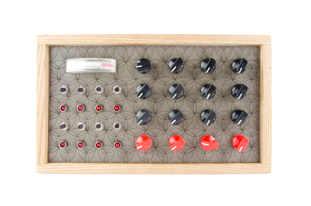
I built the front panel of my synthesizer out of chipboard, which I coated in clear enamel for rigidity. You can make it from anything you want: acrylic, wood, sheet metal, so long as it's rigid enough to hold all of the components in place. I started by just mounting all of my controls and making sure that they were all oriented correctly before wiring them up.

You'll notice there's a rectangular hole in my front panel above the step indicator lights. That's for a VU Meter that I dug up at a local surplus shop. It isn't even a VU Meter. It was apparently for indicating the operating voltage of some huge piece of equipment... anyway, I just drove it off the audio output with a diode to prevent EMF related problems and drop the line voltage into the operating range of the gauge. I won't go into any more detail about that since I'll never be able to track down a part number for you on that, and, if you go find your own, it will undoubtedly have its own special operating range.
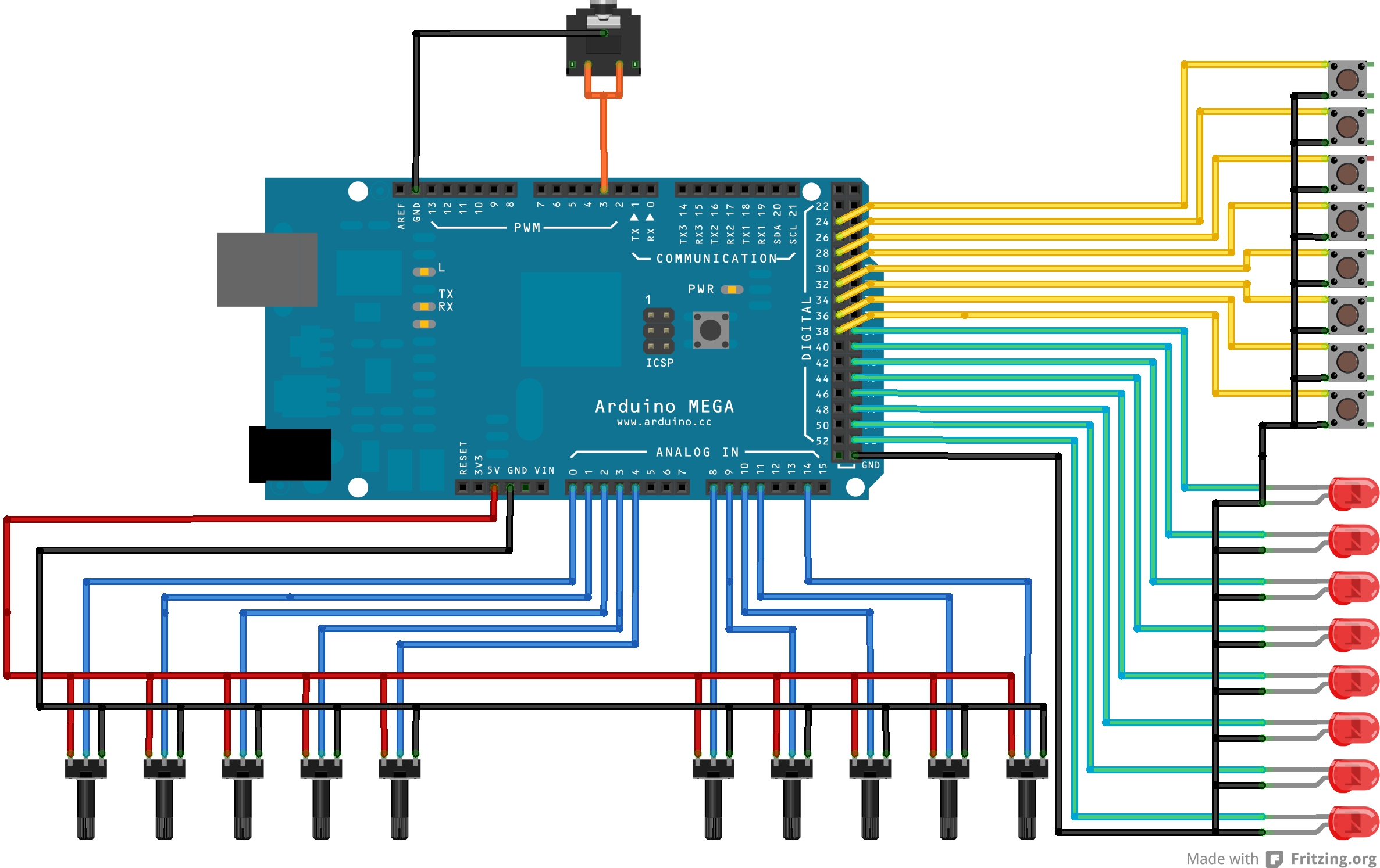
The next order of business is to wire everything. It helps to consult the code to figure out to which pin on the Arduino everything is supposed to connect. Each potentiometer gets a 5V and a GND connection. Then the center pin (the wiper) is connected to the appropriate analog input. Each LED is connected to its respective digital output as well as GND. Each button is connected to a digital input and a GND. Finally, connect the audio output to pin 13 and GND. If you're using a stereo output jack, you can tie both channels together. In this configuration, the audio jack will output 5V audio instead of standard 1V line level. Most amplifiers and headphones don't care, but just keep it in mind. I've put together the drawing below to help you wrap your head around things:
I have a bunch more potentiometers than I really need on mine because I kind of designed the panel before I knew how the synth was going to work. You could always add some filters, though, and connect them to the leftover pots.
Along with the front panel, you'll need some kind of power connection. Our Wall Adapter Power Supplies work well for that and plug directly into the Arduino. Once I stuffed everything into the enclosure, it looked like this:
And then it was time to jam...
Beautiful Music
Time to Jam. Check it out!
As you can hear, this thing makes an impressive array of sounds for what it is. It's hard to tell from the video but the panel is laid out as follows (Left to Right):
Top Row: Grain 1 Phase, Grain 1 Decay, Grain 2 Phase, Grain 2 Decay
Second Row: N/A, N/A, N/A, Sync Phase (Freq)
Third Row: Global 1 Phase, Global 1 Decay, Global 2 Phase, Global 2 Decay
Bottom Row: Step Tempo, Global Phase (Freq), N/A, N/A
Resources and Going Further
Hope you enjoyed this project and I hope you get around to building your own! If you do, link us some pictures in the discussion section of this tutorial, we'd love to see them!
If you're building your own version of this, you can find more information on Auduino here. You can also download my altered version of the sketch here.
Check out some of our other audio related tutorials: