It's a common occurrence in any office -- you're on Facebook or browsing SparkFun when all of a sudden your boss walks in to see that you're not working.
This project aims to avoid that embarrassment and frowns from management. The Boss Alarm alerts you of anyone walking into your office and automatically changes the active program on your computer. The sensors are inconspicuously hidden in cute woodland creatures that are guaranteed to brighten up your office and definitely not creep out any of your coworkers!
The Boss Alarm uses an infrared breakbeam sensor made with a few common components. The design is based on schematics from this article with a few modifications.
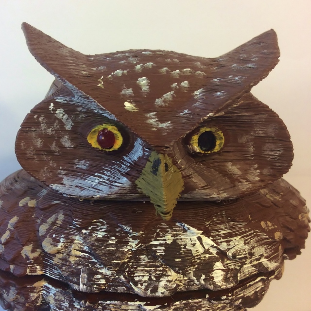
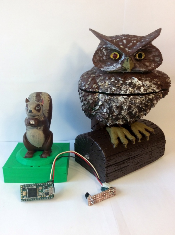
There are three components to the Boss Alarm. There is a transmitter (hidden in the squirrel) that sends an invisible beam to the owl. The owl contains an infrared receiver (namely, the TSOP38238 IR Receiver Diode) and also another infrared transmitter. The last component is another IR receiver connected to a Teensy 3.2.
The Teensy is configured as a USB keyboard device. When the beam between the owl and the squirrel is broken, the owl sends a signal to the Teensy. When the Teensy receives this signal, it simply sends the Alt+Tab keyboard command to your computer to change the active program. If you are on a different operating system, you can change the key commands to whatever you want (for example, Windows Key + D to minimize all programs). You can trigger practically anything using this project.
Check out a video of the project in action below:
You're going to need a few things to build this project yourself.
Along with those parts, you will need a few other parts and tools:
If you plan on installing the electronics in the woodland creature enclosures, you will also need access to a 3D printer and a hot glue gun. You may also wish to paint them.
I highly recommend obtaining some sort of oscilloscope for troubleshooting, but it is not necessary to complete this project. You may also want to acquire a decent multimeter for diagnosing any issues you encounter.
You may need to read up on a few subjects to wrap your head around this project:
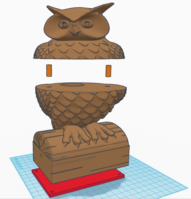
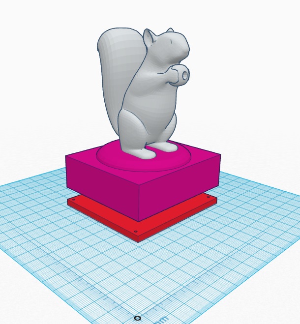
I am more of an engineer than an artist, so I sourced the basic owl and squirrel models from Autodesk's 123Dapp website. The original artist's page for the owl can be found here. And the squirrel's artist can be found here.
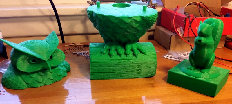
I modified the models a bit to fit the electronics inside. The owl was too tall for my printer to handle so I separated it into two parts and used printed pegs to align them. This also aids in assembly later on and isn't too noticeable. I used Autodesk's free, online program, Tinkercad, to create the models.
You should start the printer now, the models take a while to print!
The transmitter is a simple astable 555 timer circuit. The 555 timer is a popular and versatile (and some might say dated) IC found in many hobbyist projects.
The parts you need for this component of the project are:
Here's the circuit diagram:

The infrared receivers we are using have built-in filtering that makes them very reliable for digital communication. However, in order for the receivers to see our infrared beam we need to modulate it (turn it off and on) at 38kHz.
When operated in astable mode, the 555 timer will oscillate between high and low voltage at a frequency determined by external resistors and capacitors. If you want to learn more about how to work with a 555 timer, there are several websites dedicated to the chip.
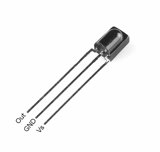
Let me remind you of the pinout for the infrared receiver:
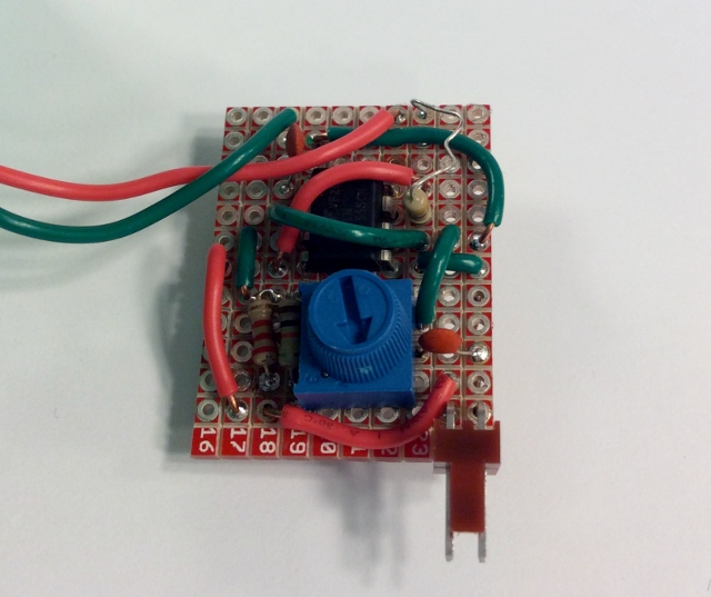
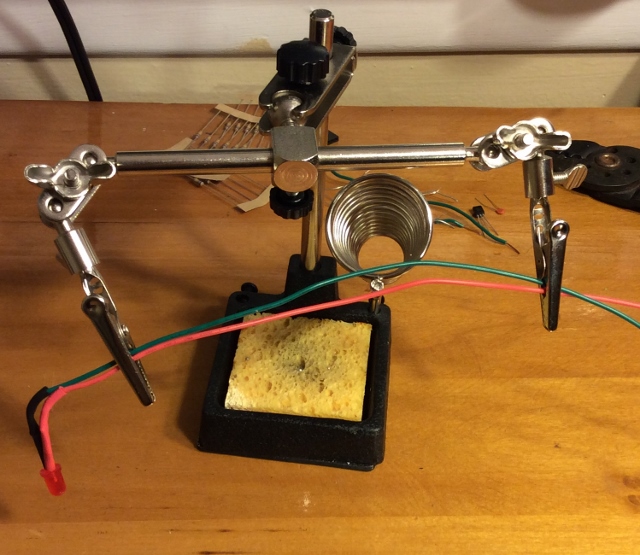
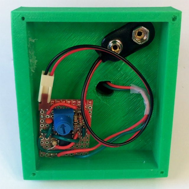
Solder together the circuit in the diagram, try to keep it a bit compact so it fits in the model nicely! The squirrel can accommodate a 9V battery and a circuit board about 1.25 X 1 and 0.5 inches tall.
Don't solder the infrared LED directly on the board. Instead, solder some longer-than-you-think-you-need wires onto the LED's terminals making sure to note which one is the anode (+) and which is the cathode (-).
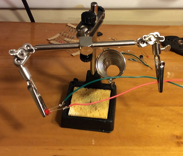
To avoid short circuits, you should put some shrink wrap tubing on the soldered connections. You can use a heat gun or a blow dryer to shrink the tubing. I used a lighter but be careful not to melt the LED or yourself.
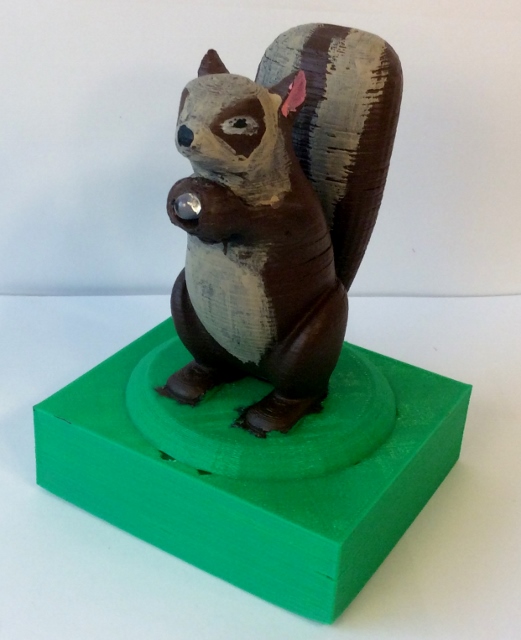
If you are using the printed models, I recommend painting them so they blend into your desk's knick-knacks better.
You can install the infrared LED in the squirrel's acorn. You may need to drill out the hole a bit to make the LED fit. Feed the wires through the model until they come out the bottom and then use a little hot glue to keep the LED in place. Tuck the wires away, and then no one will notice the squirrel is actually a nark!
Here's the circuit schematic for the owl:

The circuit for the owl may look really complicated but it's not! The owl transceiver operates in a way similar to the squirrel transmitter. Only instead of having one 555 timer circuit, the owl has TWO! Let's go through it step by step.
The owl has a 555 timer operating in monostable mode and another operating in astable mode. The IR Receiver Diode is an active low device. This means that, when it receives a signal, the output pin is pulled low. This works great with our 555 timer since the trigger pin needs to be pulled low to activate the monostable circuit.
The monostable circuit is designed to hold the output high for approximately 1 second (this timing isn't crucial) when triggered by the IR Receiver.
The next part of the circuit is our reset transistor. There are two current-limiting resistors (1kΩ for the base, 220Ω for the Red eye LED) and a 10kΩ pull-down resistor on the transistor's emitter.
Notice that the emitter is also connected to the reset pin of the second 555 timer. In most astable applications, you tie the reset pin to the supply voltage so the chip is always on. However, in this project we only want the owl to send a signal to the computer when someone walks by.
In this configuration, when the output of the first 555 is low, the transistor will be off. The pull-down resistor makes sure the voltage seen by the second 555 timer's reset pin is around 0V, keeping it off. When the circuit is triggered, the red LED and the transistor turn on. Since the transistor is conducting, the voltage at the emitter becomes high enough to enable the second 555 timer for about 1 second.
The second 555 timer is designed to operate in astable mode at 38kHz just like the circuit in the squirrel. This sends another infrared signal to your computer telling it that someone walked by!
The additional circuits shown in the schematic are the 5V regulator circuit and the infrared receiver filtering circuit. The regulator simply takes the 9 volts from the battery and outputs a stable 5V source that plays nicely with our infrared receiver. The filtering circuit has a couple capacitors that help stabilize the output of the receiver and a pull-up resistor to keep the output high when the receiver is off.
The parts you need for this component of the project are:
Build the circuit according to the included schematic. Make sure not to solder the red and infrared LEDs or the infrared receiver. Just like with the squirrel, solder on some long wires to these, and cover the connections with shrink tubing.

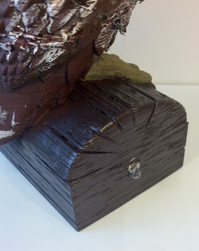
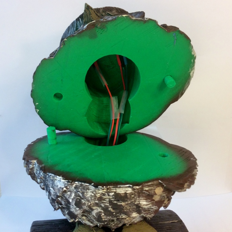
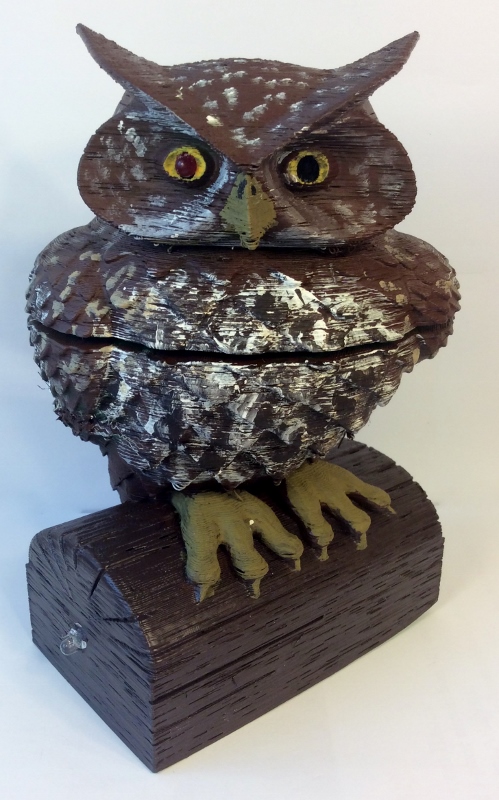
Paint the owl however you want; I went with a classic brown woodland owl. Again, you may need to drill out the mounting holes to get the parts to fit. It's best to do this before painting the models to avoid scratching the paint off.
When your model is prepped, you can install the components. The infrared LED is mounted in the hole on the side of the log. The Red LED goes in either eye of the owl. The IR receiver goes in the other eye of the owl. Solder the components to the board, and it should be all set!
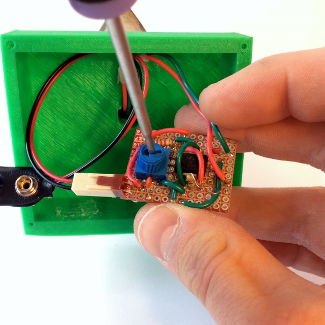
You may have noticed each astable 555 timer circuit includes a potentiometer. This allows us to fine-tune the frequency at which the circuit oscillates. We want it to be as close to 38kHz as possible so the receiver can see it in full strength.
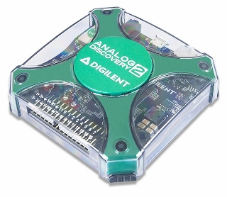
This is where an oscilloscope comes in handy. This nice piece of kit lets you visualize voltage waveforms in (pretty much) real time. My current oscilloscope is a USB-based one called the Analog Discovery 2 by Digilent. This device not only acts as a 2-channel oscilloscope but also has a 2-channel function generator, a variable power supply, a pattern generator for digital circuits, and a logic analyzer! I prefer actual lab equipment but the Analog Discovery is nice for how compact and affordable it is.
Use a small screwdriver to adjust the potentiometer. When you have it tuned just right, you may want to hot glue the knob in place so it doesn't get changed accidentally. Make sure to repeat this procedure for each transmitter circuit!
To tune the circuit without an oscilloscope, you can just play with the potentiometer until the circuit operates reliably. The IR receiver will work with frequencies that are close enough to 38kHz.
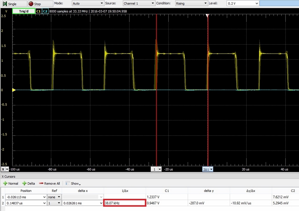
If you are lucky enough to have access to an oscilloscope, this part becomes very easy. Simply hook your probe up to the output pin of the astable 555 timer, and the waveform should appear. You can adjust the potentiometer until the frequency is about 38kHz.
With the equipment mentioned above, measure the frequency of the wave using vertical cursors, and place them one period apart. The inverse of the difference between them will be your frequency (the oscilloscope usually does this calculation for you).
If you're just getting started with the oscilloscope, you should read this guide.
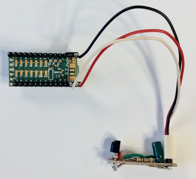
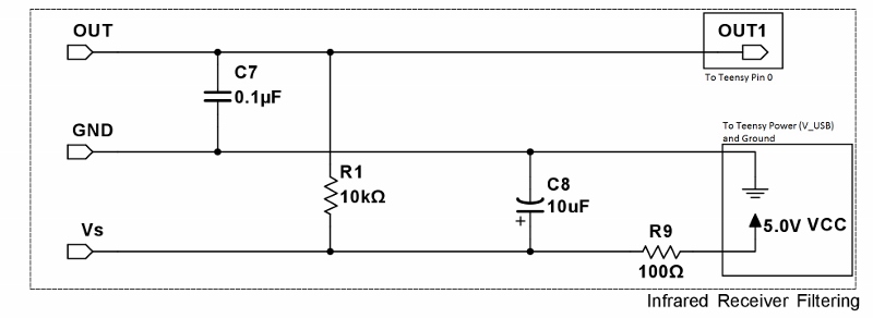
The computer receiver is just a copy of the IR filtering circuit used in the owl hooked up to a Teensy 3.2.
The parts you need for this component of the project are:
Here's the schematic again:
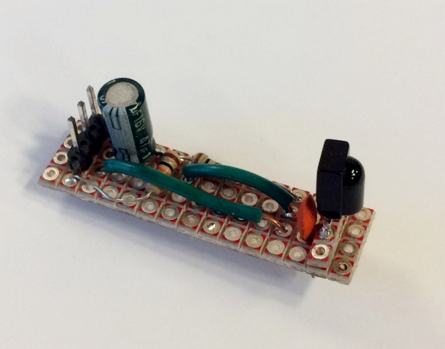
First, solder headers on your Teensy board, if you haven't already.
Solder together the IR filtering circuit, and use a connector to tie the Teensy's power and ground pins to the appropriate pins on the infrared receiver. Make sure to use the V_USB pin to get a 5V source rather than the 3.3V source on the Teensy. Connect the output of the receiver to pin 0 on the Teensy.
Plug the Teensy into your computer, and get ready to program it! If you haven't used the Teensy before, read this guide to get started.
The Teensy is like an Arduino, but it has a unique feature -- it can be configured as a USB device. This lets your computer "see" the Teensy as another device and automatically load the drivers for it. For example, you can configure the Teensy as a USB keyboard (as in this project), and, when you plug it in, your computer will see it as a keyboard -- no special software required!
The code used in this project is almost identical to the Teensy's USB keyboard example sketch. We simply treat the output of the IR receiver as a switch and send key presses/releases on the falling/rising edge of the receiver's output.
language:c
/* Title: Boss Alarm
 * Date: 3/14/2016
 * Author: Don Beckstein

   Note: You must select Keyboard from the "Tools > USB Type" menu

*/

#include <Bounce.h>

// Helps us debounce the output from the IR receiver (helps suppress false-alarms)
Bounce button0 = Bounce(0, 100);

//Change these to set the key combination used
unsigned const int modifierKey = MODIFIERKEY_ALT;
unsigned const int combinationKey = KEY_TAB;

//If you're on Mac you can try this code (I haven't tested it)
//unsigned const int modifierKey = MODIFIERKEY_GUI;
//unsigned const int combinationKey = KEY_TAB;

//If you want it to show your desktop on Windows instead of switch windows, use this code:
//Sends Windows Key + D
//unsigned const int modifierKey = MODIFIERKEY_GUI;
//unsigned const int combinationKey = KEY_D;

void setup() {
  // Configure the pins for input mode with internal pullup resistors.
  pinMode(0, INPUT_PULLUP);

}

void loop() {

  //Update the buttons
  button0.update();

  //Press keyboard keys when the IR Receiver is triggered
  if (button0.fallingEdge()) {

    //Send the key commands
    Keyboard.set_modifier(modifierKey);
    Keyboard.send_now();
    Keyboard.set_key1(combinationKey);
    Keyboard.send_now();
  }

  //Release the keyboard keys when the trigger returns to normal
  if (button0.risingEdge()) {

    //Release keys
    Keyboard.set_modifier(0);
    Keyboard.set_key1(0);
    Keyboard.send_now();
  }
}
The default key combination is ALT+Tab to switch between programs on Windows. If you have multiple monitors you might want all programs to be minimized. I included a few different key combinations in the code, you can uncomment/comment lines of code to suit your needs. I also included a key combination that should work on Mac. If you want to make your own key command, this page provides a reference to the Teensy's defined keys.
Make sure to click Tools->Board->Teensy 3.2 and Tools->USB Type->Keyboard+Mouse+Joystick to set up your Teensy correctly. Load the Boss Alarm code onto your Teensy, and it should be all set!
The squirrel and owl should be placed across from each other at the same height for best operation. Make sure the IR LED in the owl is pointing towards your computer! The Boss Alarm should work well for typical small office spaces.
Remember that light can reflect (including infrared, we just can't see it)! You may find that the IR signal coming from the squirrel gets picked up by your Teensy receiver causing false-alarms. If this happens, reposition the squirrel so it is angled away from your Teensy receiver.
Plug in the Teensy board, and that's it!
The Boss Alarm will change your active program using Alt-Tab. Make sure the last program you had selected was work-related. Excel has some nice templates that certainly look business-y.
The Boss Alarm has the unintended benefit that when your boss walks away, it will trigger again and return your active program to whatever you were doing before!
Now you can browse SparkFun at work without fear of your boss finding out. :)
Though it may seem like something out of a spy movie, you likely use this kind of technology every day. The infrared receiver in the owl's eye is the same you will find if you open up any modern TV or DVD player. That's right -- remote controls use this to send key presses!

Infrared communication has applications beyond breakbeam sensors and remote controls. NASA is using infrared lasers to speed up data transmission to and from Mars! It is also used in modern fiber-optic communication systems. For more on infrared communication, read this page on Wikipedia.
Infrared is one of my favorite communication methods to use in my projects. It is a pretty lightweight, cheap, and versatile platform. All it takes is a common IR LED and an IR receiver diode.
Another project I made for a hackathon was a multi-user chatroom that transferred messages across the room using infrared! My team even transmitted a picture over the channel. We called it IRC (pun intended, InfraRed Chat).
You can use this design as a basis for a number of other projects! See if you can modify the circuits to trigger other things using an infrared breakbeam sensor.
Aside from those mentioned in the tutorial, here are a few resources I used along the way:
If you are having trouble with the Teensy, browse through the board's website to find more information and tutorials.
If you have any interest in microelectronics, you might like this article on the internals of the 555 timer!
For more project ideas, check out these other great SparkFun tutorials.
learn.sparkfun.com | CC BY-SA 3.0 | SparkFun Electronics | Niwot, Colorado