Big Easy Driver Hookup Guide
 Toni_K
 Introduction
The Big Easy Driver gives you the capability to drive stepper motors that pull up to 2A/phase. This driver defaults to 16 step microstepping mode, and gives you control of motor speed and location.
Materials Required
To follow along with this tutorial, we recommend you have access to the following materials. You may not need everything though depending on what you have. Add it to your cart, read through the guide, and adjust the cart as necessary.
You can either solder screw terminals or standard headers for attaching things to the Big Easy Driver. The best option for you will depend on your application.
Suggested Reading
If you aren't familiar with the following concepts, we recommend reviewing them before beginning to work with the Big Easy Driver.
How to Solder: Through-Hole Soldering
Battery Technologies
How to Power a Project
Working with Wire
Installing Arduino IDE
Motors and Selecting the Right One
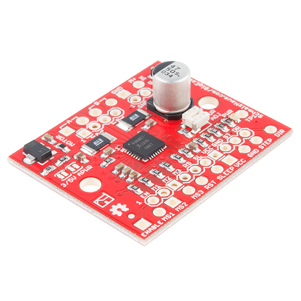
Hardware Overview
The Big Easy Driver is designed around the Allegro A4988 motor driver. Each pin present on the board has two connection points. The first, which are the pins closest to the center of the board, are spaced out to fit standard 0.1" headers. The secondary connection points are closest to the edge of the board, and are spaced to fit 2-pin screw terminals. You can use whichever pin connections work best for your project. Functionality between the two sets does not change.
Pin Descriptions
Several pins of the A4988 IC are broken out on the Big Easy Driver, allowing direct connection to a bi-polar stepper motor, as well as a microcontroller.
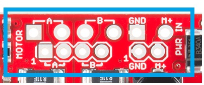
Board Top Pins
Coil A+: DMOS Full Bridge 1 Output B. Half of connection point for bi-polar stepper motor coil A.
Coil A-: DMOS Full Bridge 1 Output A. Other half of connection point for bi-polar stepper motor coil A.
Coil B+: DMOS Full Bridge 2 Output B. Half of connection point for bi-polar stepper motor coil B.
Coil B-: DMOS Full Bridge 2 Output A. Other half of connection point for bi-polar stepper motor coil B.
GND: Ground.
M+: Power supply. 8V - 35V.
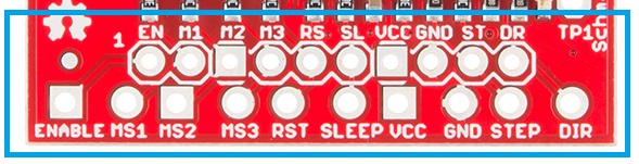
Bottom Pins
ENABLE: Logic Input. Enables the FET functionality within the motor driver. If set to HIGH, the FETs will be disabled, and the IC will not drive the motor. If set to LOW, all FETs will be enabled, allowing motor control.
MS1: Logic Input. Microstep Select 1 has a pull-up resistance of 20 kOhms. See truth table below for HIGH/LOW functionality.
MS2: Logic Input. Microstep Select 2 has a pull-up resistance of 20 kOhms. See truth table below for HIGH/LOW functionality.
MS3: Logic Input. Microstep Select 3 has a pull-up resistance of 20 kOhms. See truth table below for HIGH/LOW functionality.
| MS1 | MS2 | MS3 | Microstep Resolution | Excitation Mode |
|---|---|---|---|---|
| L | L | L | Full Step | 2 Phase |
| H | L | L | Half Step | 1-2 Phase |
| L | H | L | Quarter Step | W1-2 Phase |
| H | H | L | Eigth Step | 2W1-2 Phase |
| H | H | H | Sixteenth Step | 4W1-2 Phase |
RST: Logic Input. When set LOW, all STEP commands are ignored and all FET functionality is turned off. The translator is set to the Home state as well. This must be set HIGH to enable functionality of the motor driver.
SLEEP: Logic Input. When set to LOW, the A4988 enters sleep mode, and disables functionality of the FETs, internal current regulator and charge pump. When switching this pin to HIGH to wake up the IC, allow 1 ms of delay before sending a STEP signal. The IC will return the FETs to the home microstepping position found in the diagrams on page 14 of the datasheet upon receiving a HIGH signal on this pin.
VCC: Logic Supply.
GND: Ground.
STEP: Logic Input. Any transition on this pin from LOW to HIGH will trigger the motor to step forward one step. Direction and size of step is controlled by DIR and MSx pin settings.
DIR: Logic Input. This pin determines the direction of motor rotation. Changes in state from HIGH to LOW or LOW to HIGH only take effect on the next rising edge of the STEP command.
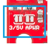
Solder Jumpers
There are two solder jumpers present on the board.
APWR - This solder jumper allows the user to use VCC as a power supply for external devices. The Big Easy Driver requires 15mA to operate, and the voltage regulator that outputs VCC can only supply 100mA. Keep this in mind when planning to power any additional devices off of VCC.
5V/3.3V - This jumper allows the user to set the configuration of VCC between 3.3V or 5V. With the jumper open, VCC will be 5V. If the jumper is closed, VCC is 3.3V.
Potentiometer
The potentiometer on board is included to allow users the ability to select the current provided to the motor. It ranges from 0mA to 2000mA (2A). This will require you to be aware what current range your motor can handle - check the motor's data sheet for the current settings.
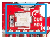
If you can't find this information, have no fear -- you can still find the proper setting for the potentiometer. First, set it to the lowest setting of the potentiometer. Keep in mind that the potentiometer is delicate, so be careful to not force the potentiometer past the mechanical stops when turning it. Once you have the motor being driven at a slow, yet steady speed, slowly turn the potentiometer and pay attention to the motor's behavior. You should find a sweet spot where the motor doesn't skip or jerk between steps.
Hardware Hookup
Connect Motor Coil Wires
You will need to determine the wire pairs for each coil on the motor you plan to use. The most reliable method to do this is to check the datasheet for the motor.
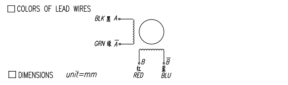
However, if you are using a 4-wire or 6-wire stepper motor, it is still possible to determine the coil wire pairs without the datasheet.
For a 4-wire motor, take one wire and check its resistance against each of the three remaining wires. Whichever wire shows the lowest resistance against the first wire is the pair mate. The remaining two wires should show similar resistance between the two of them.
For a 6-wire motor, you will need to determine which of three the wires go together for one coil. Pick one wire, and test this against all other wires. Two wires should show some resistance between them and the first wire picked, while the other three will show no connection at all. Once the three wires for one coil have been determined, find two of the three that show the highest resistance between them. These will be your two coil wires. Repeat for the second group of three wires.
Once you have determined the coil wire pairs, you will need to attach them to the Big Easy Driver. The first coil pair should be plugged into Coil A+ and Coil A-, while the second coil pair plugs into Coil B+ and Coil B-. There is no polarity on the coils, so you don't need to worry about plugging in a coil backwards on the board. In our example, we are using a 4-coil motor. The connections between the Big Easy Driver and motor are as follows.
Big Easy Driver → Motor
- A+ → Red Wire
- A- → Green Wire
- B+ → Blue Wire
- B- → Yellow Wire
Connect a Power Supply
Once your motor is connected, you can then connect a power supply to the Big Easy Driver. You can use any kind of power supply (desktop, wall adapter, battery power, etc.), but verify that whatever choice you go with is capable of providing up to 2A and falls in the range of 8V to 35V.
Power supplies with a current limiting feature: If you use a power supply that has a current limiting feature, you need to either disable that feature, or turn the maximum current level up to a point above what you expect your motor to draw. If your power supply attempts to limit current to the Big Easy Driver, it can damage the board.
Connect the power supply to M+ and GND. REMEMBER to disconnect the power before connecting/disconnecting your motor.
Connect a Microcontroller
For this example, we will be using an Arduino Uno R3. However, any microcontroller that works at 3.3V or 5V logic and has digital I/O will work for this example.
Here are the following pin connections for our example.
Uno → Big Easy Driver
- D2 → STEP
- D3 → DIR
- D4 → MS1
- D5 → MS2
- D6 → MS3
- D7 → ENABLE
- GND → GND
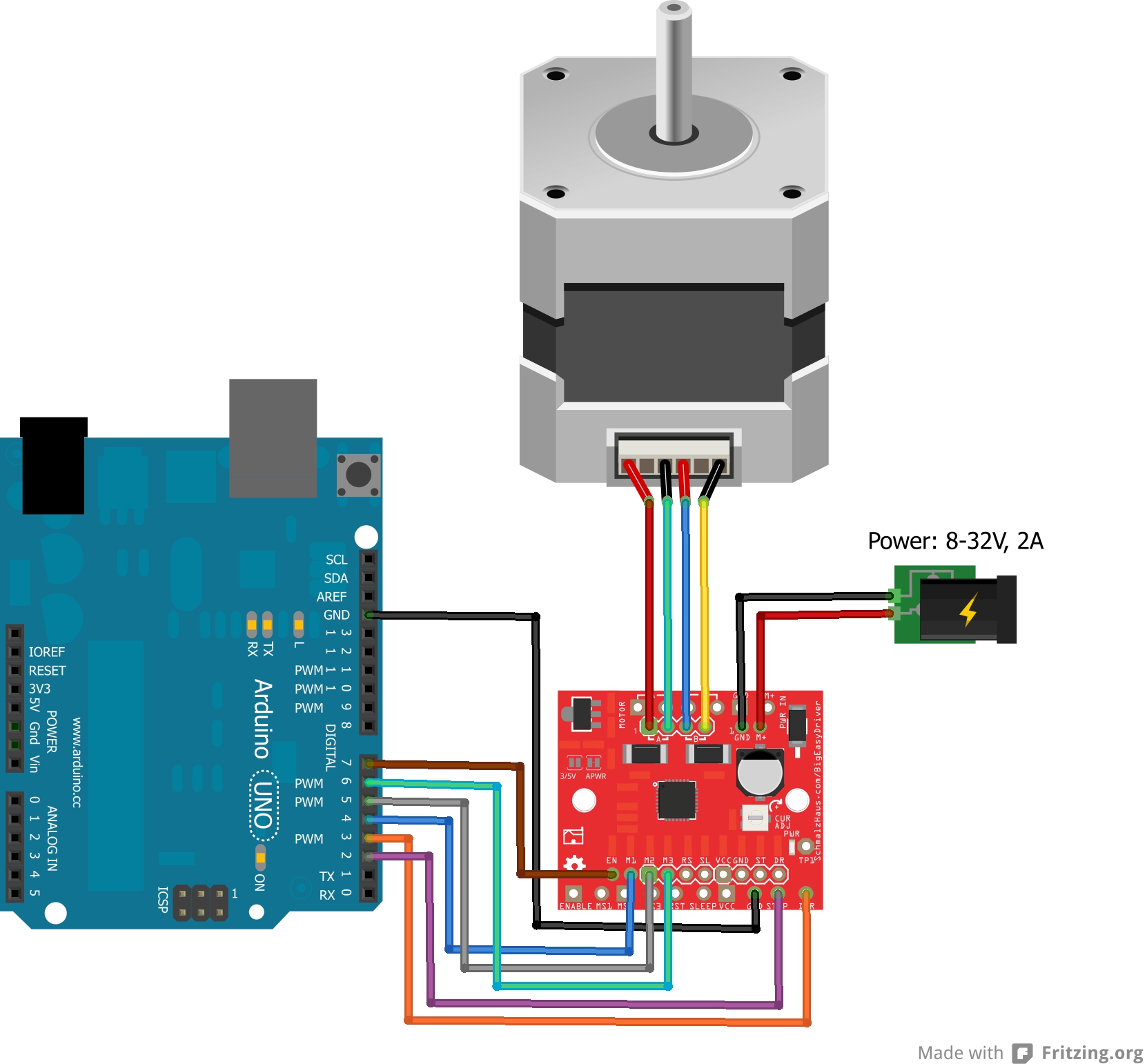
Final Circuit
Once everything is connected, your setup should look like this:
Arduino Code
Basic Arduino Example
Now that you have the hardware hooked up and ready to go, it's time to get the code uploaded. For the most up-to-date code available, please check the GitHub repository. Or download the Arduino code from the link below. Navigate to Big_Easy_Driver > Firmware > SparkFun_Big_ Easy_Driver_Basic_Demo > SparkFun_Big_Easy_Driver_Basic_Demo.ino example and open it in the Arduino IDE.
The first section of the sketch defines all of the pin connections between the Arduino and the Big Easy Driver. It also sets these pins as outputs, and puts them to the proper logic levels to begin driving the motor.
language:c
//Declare pin functions on Arduino
#define stp 2
#define dir 3
#define MS1 4
#define MS2 5
#define MS3 6
#define EN  7

//Declare variables for functions
char user_input;
int x;
int y;
int state;

void setup() {
  pinMode(stp, OUTPUT);
  pinMode(dir, OUTPUT);
  pinMode(MS1, OUTPUT);
  pinMode(MS2, OUTPUT);
  pinMode(MS3, OUTPUT);
  pinMode(EN, OUTPUT);
  resetBEDPins(); //Set step, direction, microstep and enable pins to default states
  Serial.begin(9600); //Open Serial connection for debugging
  Serial.println("Begin motor control");
  Serial.println();
  //Print function list for user selection
  Serial.println("Enter number for control option:");
  Serial.println("1. Turn at default microstep mode.");
  Serial.println("2. Reverse direction at default microstep mode.");
  Serial.println("3. Turn at 1/16th microstep mode.");
  Serial.println("4. Step forward and reverse directions.");
  Serial.println();
}
One thing worth noting is that the code also initializes the serial connection at 9600 bps. This enables the user (you!) to control the motor's functionality and debug your circuit if needed.
The main loop of the code is pretty simple. The Arduino scans the serial port for input from the user. When it is received, it's compared to the four possible functions for the motor, which are triggered from user input. If no valid input is received, the Arduino prints an error over the serial port. After the requested function is completed, the pins on the Big Easy Driver are reset to the defaults.
language:c
//Main loop
void loop() {
  while(Serial.available()){
      user_input = Serial.read(); //Read user input and trigger appropriate function
      digitalWrite(EN, LOW); //Pull enable pin low to set FETs active and allow motor control
      if (user_input =='1')
      {
         StepForwardDefault();
      }
      else if(user_input =='2')
      {
        ReverseStepDefault();
      }
      else if(user_input =='3')
      {
        SmallStepMode();
      }
      else if(user_input =='4')
      {
        ForwardBackwardStep();
      }
      else
      {
        Serial.println("Invalid option entered.");
      }
      resetBEDPins();
  }
}
Driving Stepper Motor in Forward
The first of the four functions this demo sketch enables is a basic example to show the motor spinning in one direction. The direction pin is held LOW, which for our sketch, we define as the 'forward' direction. The sketch then transitions the step pin HIGH, pauses, and then pulls it LOW. Remember, the motor only steps when the step pin transitions from LOW to HIGH, thus we have to switch the state of the pin back and forth. This is repeated 1000 times, and then the Arduino requests more user input to determine the next motor activity.
language:c
//Default microstep mode function
void StepForwardDefault()
{
  Serial.println("Moving forward at default step mode.");
  digitalWrite(dir, LOW); //Pull direction pin low to move "forward"
  for(x= 0; x<1000; x++)  //Loop the forward stepping enough times for motion to be visible
  {
    digitalWrite(stp,HIGH); //Trigger one step forward
    delay(1);
    digitalWrite(stp,LOW); //Pull step pin low so it can be triggered again
    delay(1);
  }
  Serial.println("Enter new option");
  Serial.println();
}
Driving Stepper Motor in Reverse
The reverse function works exactly the same as the forward function. The only difference is that instead of pulling the direction pin LOW, we set it HIGH, thus switching the direction of the motor spin. One thing you can try on either of these first two functions is modifying the motor speed by changing the value in delay(). It is currently set to 1 microsecond, making each step pulse take 2 microseconds. Increasing the delay will slow down the motor, while decreasing the delay will speed up the motor.
language:c
//Reverse default microstep mode function
void ReverseStepDefault()
{
  Serial.println("Moving in reverse at default step mode.");
  digitalWrite(dir, HIGH); //Pull direction pin high to move in "reverse"
  for(x= 0; x<1000; x++)  //Loop the stepping enough times for motion to be visible
  {
    digitalWrite(stp,HIGH); //Trigger one step
    delay(1);
    digitalWrite(stp,LOW); //Pull step pin low so it can be triggered again
    delay(1);
  }
  Serial.println("Enter new option");
  Serial.println();
}
Microstepping
The third function shows off the different microstepping functionality that the Big Easy Driver provides. To enable the motor to step in 1/16th microsteps, we must set MS1, MS2, and MS3 HIGH. This sets the logic of the board to 1/16th microstep mode. If you want to have the motor step at a different microstep mode, change the settings for one of the MS# pins. Check the truth table in the Hardware Overview section, if you need a reminder of what settings are enabled by the various pin states.
language:c
// 1/16th microstep foward mode function
void SmallStepMode()
{
  Serial.println("Stepping at 1/16th microstep mode.");
  digitalWrite(dir, LOW); //Pull direction pin low to move "forward"
  digitalWrite(MS1, HIGH); //Pull MS1,MS2, and MS3 high to set logic to 1/16th microstep resolution
  digitalWrite(MS2, HIGH);
  digitalWrite(MS3, HIGH);
  for(x= 0; x<1000; x++)  //Loop the forward stepping enough times for motion to be visible
  {
    digitalWrite(stp,HIGH); //Trigger one step forward
    delay(1);
    digitalWrite(stp,LOW); //Pull step pin low so it can be triggered again
    delay(1);
  }
  Serial.println("Enter new option");
  Serial.println();
}
Forward and Reverse
The final motor function available shows how the motor can change direction on the fly. The function works just as the forward and reverse functions above, but switches between states quickly. This example will step the motor 1000 steps forward and then reverse 1000 steps. This allows you to precisely move something with the motor in one direction, and return to the starting position exactly. Precise position control is a great benefit of stepper motors!
language:c
//Forward/reverse stepping function
void ForwardBackwardStep()
{
  Serial.println("Alternate between stepping forward and reverse.");
  for(x= 1; x<5; x++)  //Loop the forward stepping enough times for motion to be visible
  {
    //Read direction pin state and change it
    state=digitalRead(dir);
    if(state == HIGH)
    {
      digitalWrite(dir, LOW);
    }
    else if(state ==LOW)
    {
      digitalWrite(dir,HIGH);
    }

    for(y=0; y<1000; y++)
    {
      digitalWrite(stp,HIGH); //Trigger one step
      delay(1);
      digitalWrite(stp,LOW); //Pull step pin low so it can be triggered again
      delay(1);
    }
  }
  Serial.println("Enter new option");
  Serial.println();
}
Once the requested action is completed, the pins must be set back to the default state to prevent unexpected or unwanted motor behavior. We use the resetBEDPins() function to achieve this.
language:c
//Reset Easy Driver pins to default states
void resetBEDPins()
{
  digitalWrite(stp, LOW);
  digitalWrite(dir, LOW);
  digitalWrite(MS1, LOW);
  digitalWrite(MS2, LOW);
  digitalWrite(EN, HIGH);
}
Additional Examples
In addition to the example here, you can also install the AccelStepper Library. There are some additional examples with this library that may be beneficial to you for use with your Big Easy Driver. Download this and install the library in your Arduino libraries directory.
You can also find some additional examples on Brian's Easy Driver examples page. The examples work for both the Easy Driver and Big Easy Driver.
Resources and Going Further
Check out these additional resources for more information and other project ideas.
- Schematic (PDF)
- Eagle Files (ZIP)
- A4988 Datasheet
- Arduino AccelStepper Library
- Schmalz Haus Big Easy Driver Homepage
- Autonomous Vehicle Competition
- GitHub Repository
Now that you've successfully got your Big Easy Driver up and running, it's time to incorporate it into your own project! Looking for inspiration, check out some of these blog posts.
If you have any feedback, please visit the comments or contact our technical support team at TechSupport@sparkfun.com.