ATX Power Connector (4-Pin) Breakout Hookup Guide
Hardware Assembly
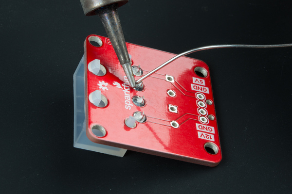
You'll need to solder the connectors of your choice to the breakout. If you have not soldered before, check out our tutorial below for tips!
How to Solder: Through-Hole Soldering
Soldering the Input Connector
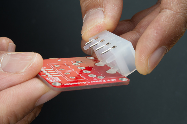
You'll need to decide on an ATX connector to solder on the breakout board. The board is compatible with both right angle and vertical connectors. We'll be using the right angle connector since the board is available in SparkFun's catalog. When inserting the right angle connector, make sure to insert the support legs first before inserting the pins into the through hole pads.
 |
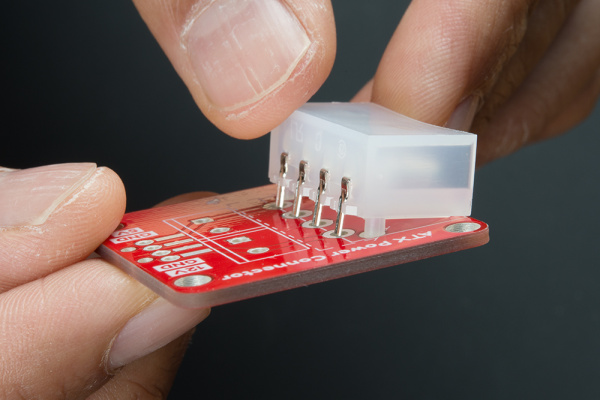 |
| Insert Support Leg into Breakout | Sliding Pins into Breakout |
Once you have chosen the ATX connector of your choice, solder each pin to the breakout.
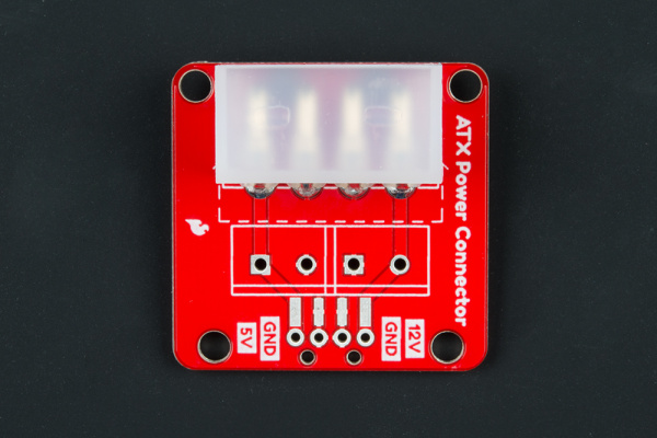
Your board should look similar to the image to the left for the right angle connector. If you happen to have a vertical connector from a different distributor, your board should look similar to the image on the right.
 |
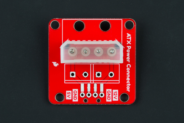 |
| Right Angle Connector Soldered | Vertical Connector Soldered |
Soldering the Output Connector
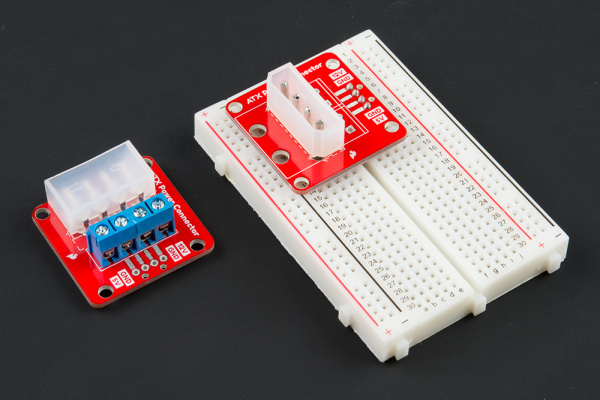
Depending on your application, you can solder screw terminals or header pins to the breakout. With the screw terminals you can easily secure fork connectors or wires. If you choose the screw terminal route, you may need to strip wires before tightening the screws down for each respective pin. Should you decide to solder straight header pins, you can insert the board into a breadboard or protoboard. There is also an option to solder right angle SMD headers to the board as well depending on your application. Below are a few configurations depending on the connector and header that you choose. Remember, the SparkFun catalog only has the right angle connector available.
