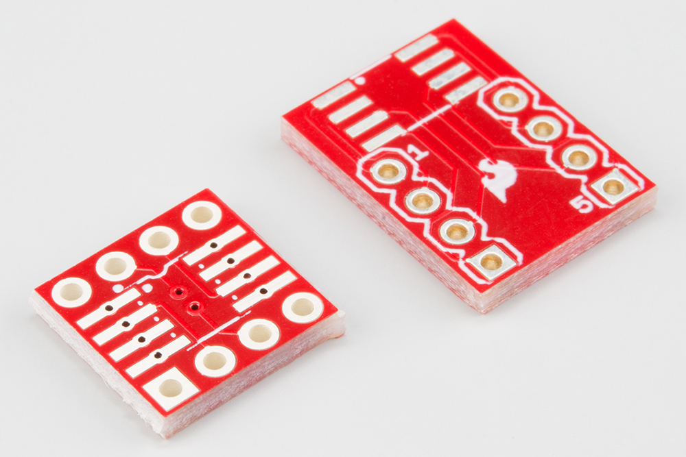
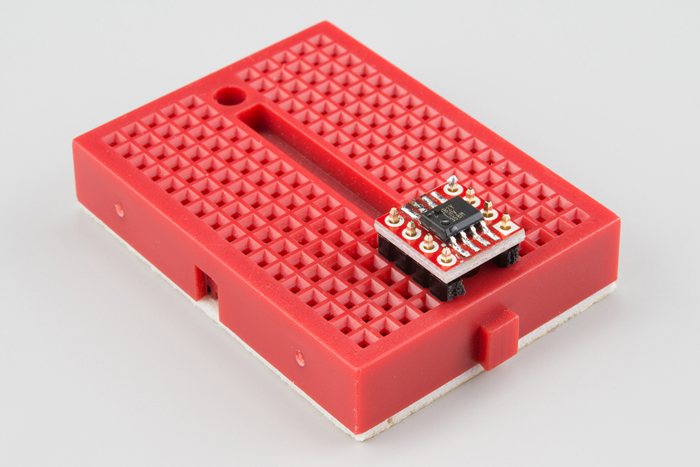
The SparkFun 8-Pin SOIC to DIP Adapter is a small PCB that lets you adapt SOIC packages into a DIP footprint. These are useful for modding and upgrading devices that use 8-pin DIP ICs, when the upgraded IC is only available in a SOIC footprint. You can also use it for prototyping, to make SOIC packages compatible with solderless breadboards.
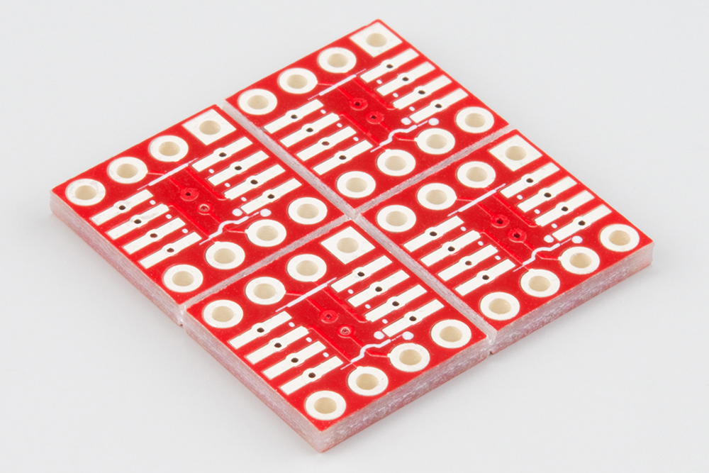
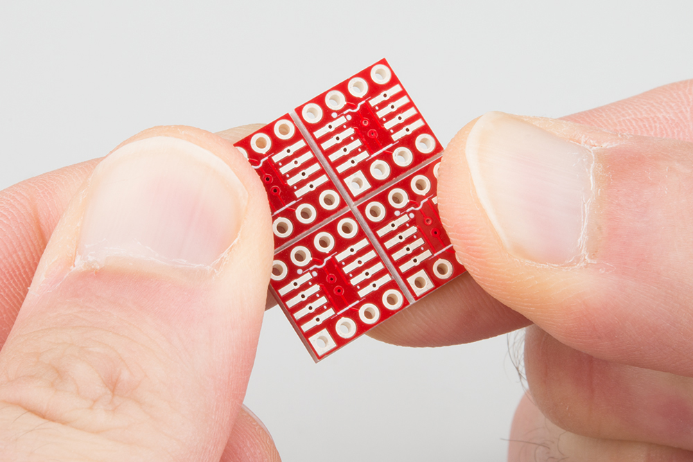
The updated version of this adapter comes as a small array of PCBs -- if you're adapting one chip, you're likely to adapt more than one. The PCBs easily snap apart, resulting in four individual boards.
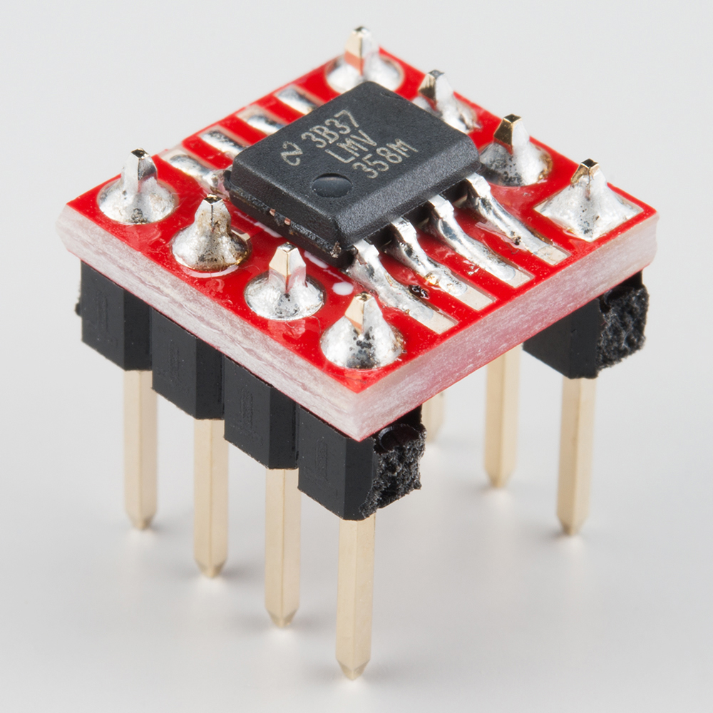
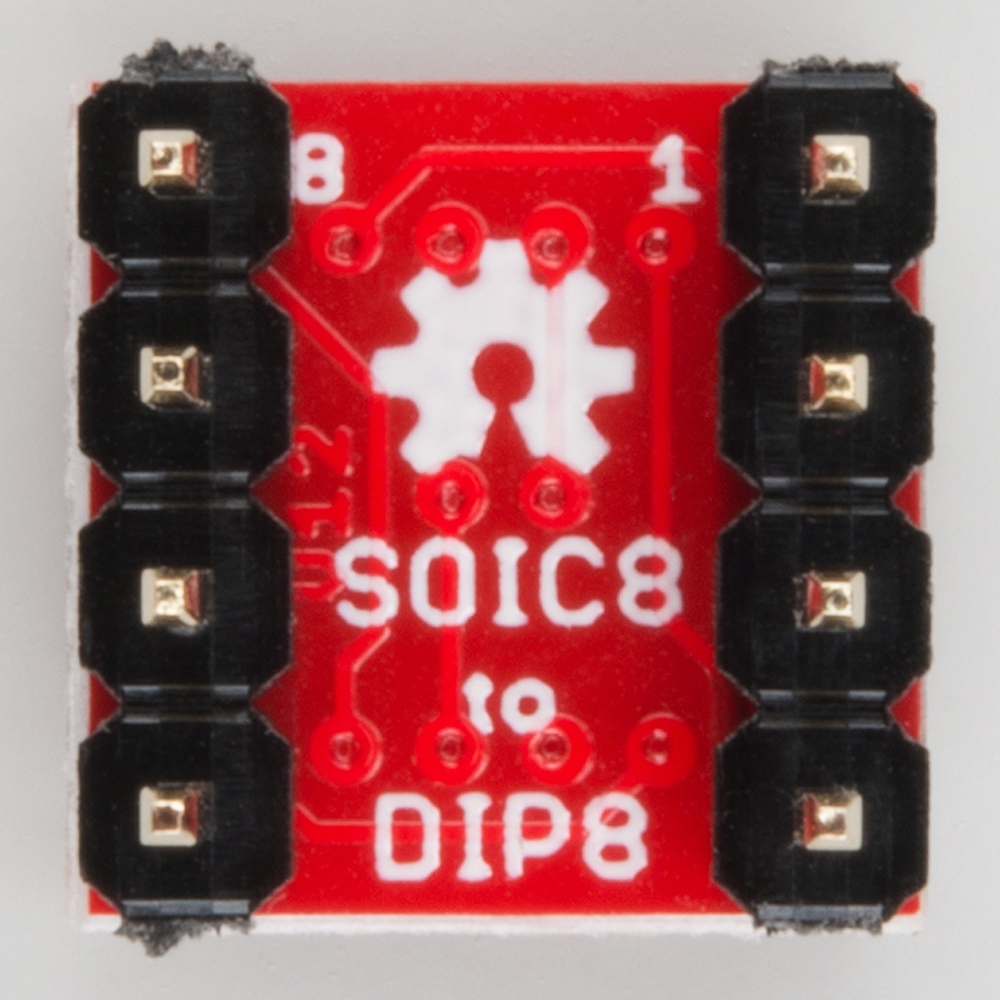
The SOIC land pattern on the board has also been improved from its predecessor. The pads are very long, in order to accomodate both narrow and wide packages. The SOIC lands are staked down with plated through-holes, to prevent lifting during rework. The SOIC is also contained entirely within the DIP outline, for situations with no extra clearance around the IC.
Check out any of the links below, if you are unfamiliar with a given topic.
Assembling the adapter is fairly straightforward, but there are a couple of tricks that make it easier.
To build up an adapter, you'll need the following pieces.
The following tools are also recommended.
The array of boards was scored when it was manufactured. If you bend along the scores, the boards snap apart easily.
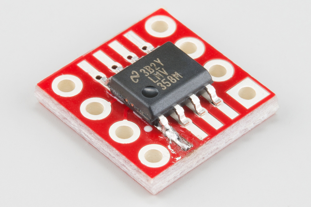
It's easiest to solder the IC in place before you mount the headers, so you don't have to work around the protruding pins.
If this is your first time soldering surface mount ICs, patience and a steady hand are the key to good solder joints.
First, heat one corner land (aka pad) on the PCB.
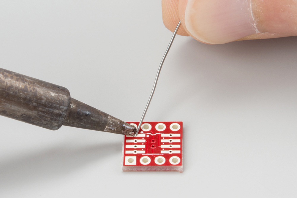
Once it's hot, flow a little solder onto it.

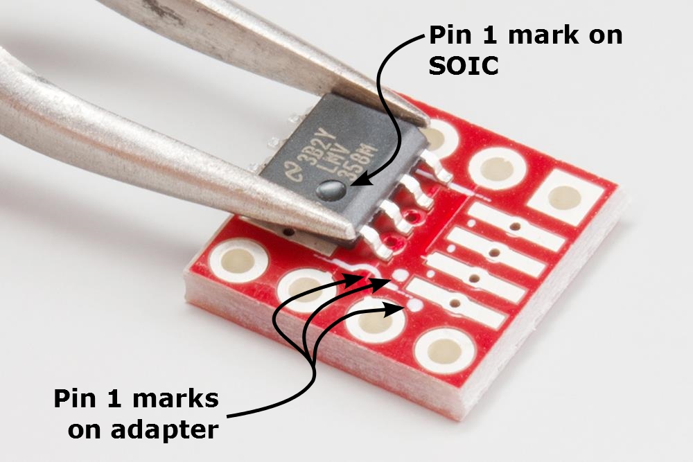
Pin 1 of the IC is usually marked with a small dimple in the IC body, or that end of the chip is marked with a notch. Line these marks up with the corresponding marks in the silkscreen. The silkscreen actually has three marks, a notch at one end of the IC, a dot within the IC outline, and a dot just outside the IC (which remains visible once the IC is soldered down).
Grab the IC with the tweezers, and orient it over the footprint. Reheat the solder blob from the previous step, so the IC lead adheres to it. Press the IC down flat before the solder cools.
At this point, it doesn't have to be a perfect solder fillet, but the IC should be sitting flat on the board, and all of the leads should align with the PCB pads. If the alignment isn't good, or if pin one is the wrong way around, reheat the solder, and adjust the placement. This becomes a lot harder to fix after more pads get soldered down.
With the chip properly aligned, you can work your way around the chip, soldering each lead. It works best if you use the tip of the soldering iron to heat the IC lead and the PCB land at the same time, then flow a tiny bit of solder to join them.
When you get back to the first lead, you can reheat the joint, flow a little more solder, and make sure the leave a neat fillet.
With the IC in place, now you can solder on the header pins. It's easier if you have a jig that can hold the pins while you solder. It turns out that a solderless breadboard has a bunch of holes with the proper alignment!
Start by breaking off the 4-pin segments off the header. Insert them into the breadboard, two rows apart.
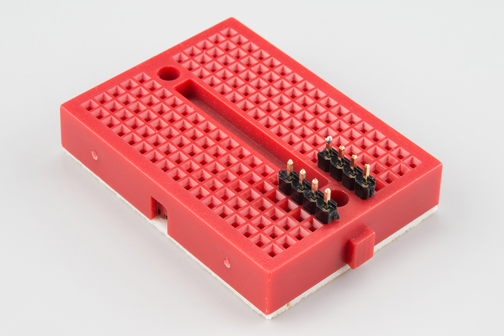
Set the PCB over the headers. Take care to keep the pins aligned straight up and down.
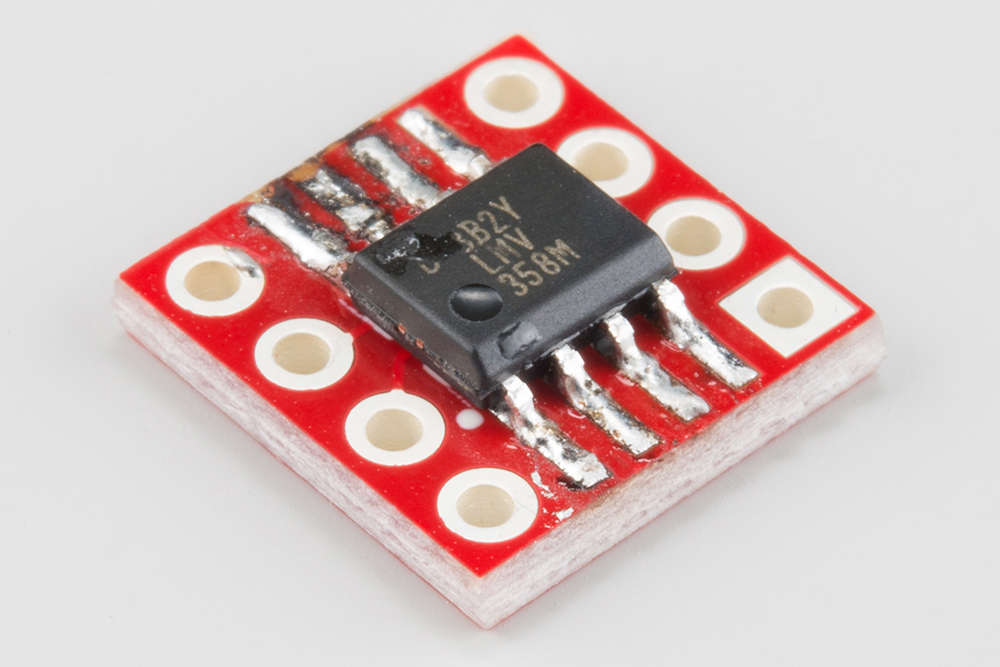
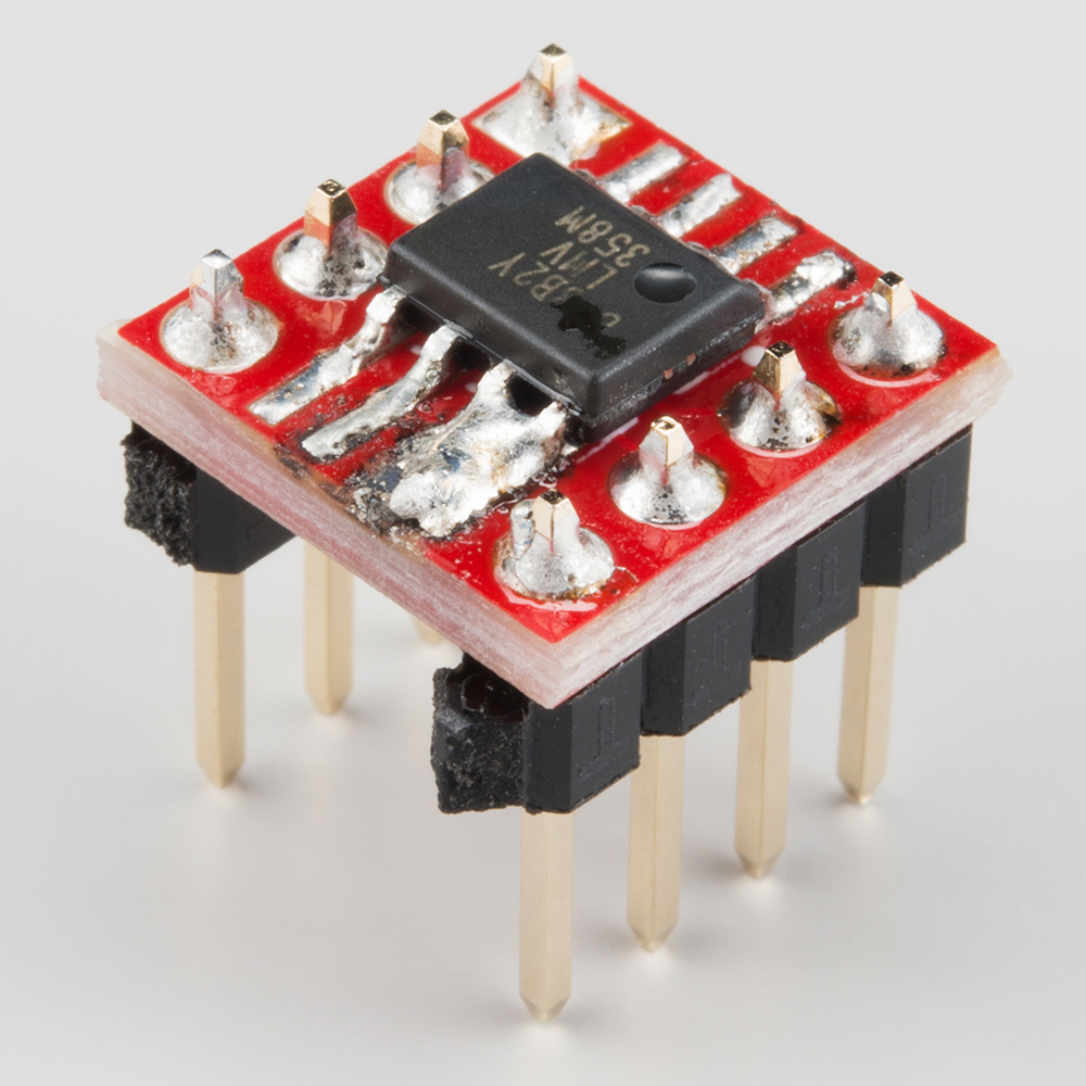
Work your way around the PCB, soldering each pin from the top of the board. When it's complete, it should look like the board below.
Once you've finished soldering, look at the solder joints. If they appear to have a yellow or brown coating on or around them, the board has flux residue (under a magnifying glass, it might look like burnt sugar). Water soluble flux is acidic, and can cause problems with long-term reliability, so it's best to clean it off.
You'll have to check the documentation for your solder for the proper cleaning methodology. Some flux is water soluble, while some requires a solvent like isopropyl alcohol or acetone.
Before we jump into applications of the SOIC-to-DIP adapter board, let's take a moment to doublecheck our work.
A quick visual inspection can help spot solder bridges, or solder joints that didn't flow properly. It's also a good time for one last check, to make certain that pin one of the SOIC is properly oriented.
For a little extra confidence, you can also use a multimeter in continuity mode, to verify that the legs of the SOIC are connected to the pins.
The pins of the DIP footprint are rotated 90° in relation to the pins of the SOIC. We covered the pin-1 markings for the SOIC in the assembly section.
Pin 1 of the DIP footprint is marked two ways.
First, the solder pad for pin 1 is square, while the others are round.
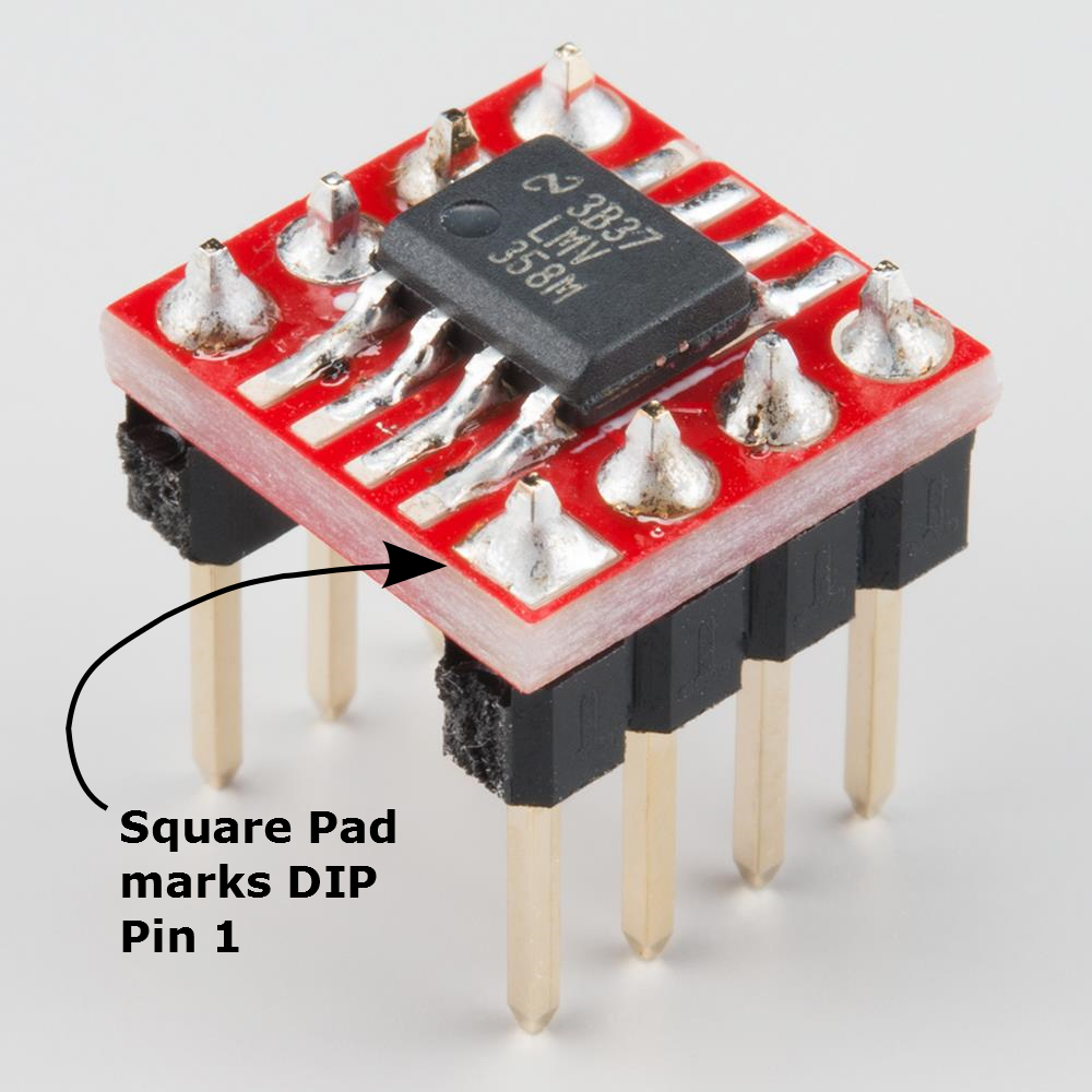
Second, pins 1 and 8 are marked in the legend silkscreened on the bottom of the board.
This adapter is useful when you want to build a breadboard prototype using a chip that's only available in SOIC. It allows the chip to properly fit the rows of the breadboard.
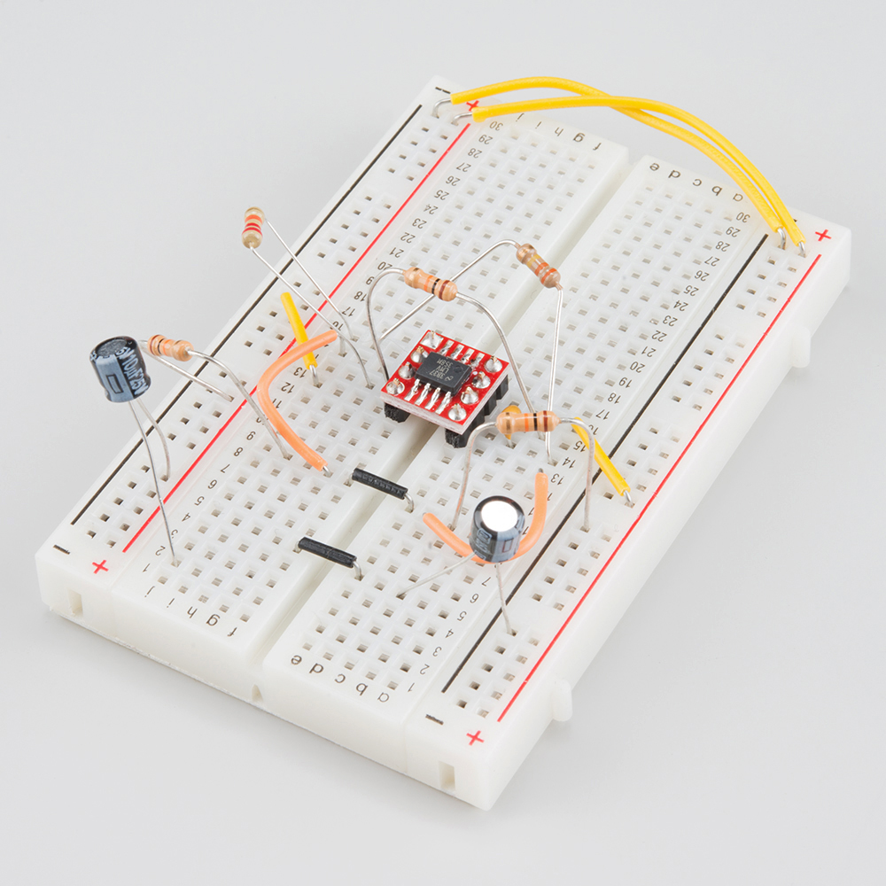
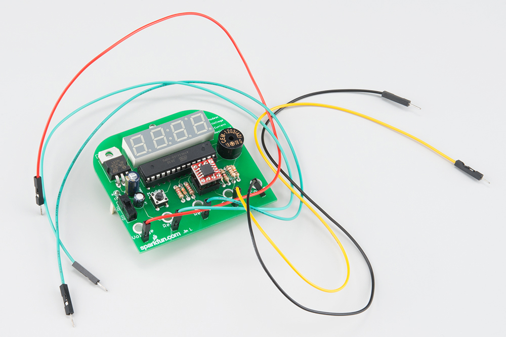
Another common use of a SIOC-to-DIP adapter is upgrading or modifying existing equipment.
At one time, this was a way to update the BIOS on a PC motherboard, though more recently DIP-8 EPROMS have been less prevalent, and surface-mount memories are more commonplace, which are usually reprogrammable without being removed from the motherboard.
Chip substitution is also a common practice among hi-fi and pro audio enthusiasts, sometimes called chip rolling or POOGE-ing (Progressive Optimization Of Generic Equipment). Many of these devices are filled with single or dual operational amplifiers in DIP-8 packages. It can be an easy, inexpensive upgrade for an older device to put in newer opamps, which feature lower distortion, less intrinsic noise, and lower DC-offset. Sometimes these newer amplifiers are only available in surface-mount packages, such as the Texas Instruments OPA1641/1642.
When doing modifications of this sort, there are a couple of things to be aware of.
This board is a redesign of the now retired 8-Pin SOIC-DIP adapter.
If you're debugging SOIC-8 based designs, you might find the SOIC-8 test clip to be useful.
We also offer a number of other surface mount to through-hole conversion boards:
learn.sparkfun.com | CC BY-SA 3.0 | SparkFun Electronics | Niwot, Colorado