$14.50
The TB6612FNG is an easy and affordable way to control motors. The TB6612FNG is capable of driving two motors at up to 1.2A of constant current. Inside the IC, you'll find two standard H-bridges on a chip allowing you to not only control the direction and speed of your motors but also stop and brake. This guide will cover in detail how to use the TB6612FNG breakout board. The library for this guide will also work on the RedBot Mainboard as well since it uses the same motor driver chip.
To follow along with the motor driver example in this tutorial, here are the basic components you will need:
Before continuing with this guide, you may want to check out any topics from the list below that sound unfamiliar.
Before we get started, let's talk about how to find a motor driver for your needs.
The first step is to figure out what type of motors you are using and to research their specifications. Picking a motor driver for a motor that is not powerful enough isn't helpful. Also, keep in mind there are different motor types (stepper, DC, brushless), so make sure you are looking for the correct type of motor driver.
You will need to spec your motor driver and make sure its current and voltage range are compatible with your motor(s).
First, you need to make sure your motor driver can handle the rated voltage of your motors. While you can usually run motors a bit above their ratings, it tends to reduce the lifespan of the motor.
Current draw is the second factor. Your motor driver needs to be capable of driving as much current as your motors will pull. As a general rule, go straight to the stalled current number for a motor (the current draw present when you are holding the motor still). A motor will pull the maximum current when it is stalled. Even if you don't plan on stalling your motor in your project, this is a safe number to use. If your motor driver can't handle that much current, then it is time to find a new motor driver (or motor). You may also notice motor drivers often have max continuous current and max peak current listed. These specs are worth noting depending on your application and how much stress your motor will endure.
This guide covers the TB6612FNG motor driver which has a supply range of 2.5V to 13.5V and is capable of 1.2A continuous current and 3.2A peak current (per channel), so it works pretty well with most of our DC motors. If the TB6612FNG does not fit your project's specifications, check out our various other motor driver boards.
As with any board, there are other things to consider such as the logic voltage, which is basically the voltage it uses to talk to your microcontroller, and heat dissipation. While these things definitely need to be considered, they are relatively easy to fix with things like level shifters and heat sinks. However, if your motor is trying to pull more current than your driver can handle, there isn't much you can do to fix it.
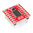
Let's discuss the pinout for the TB6612FNG breakout. We basically have three types of pins: power, input, and output, and they are all labeled on the back of the board.
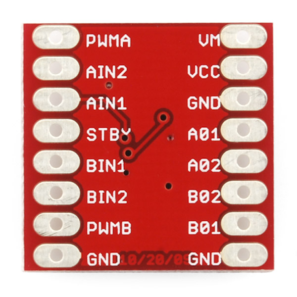
Each pin and its function is covered in the table below.
| Pin Label | Function | Power/Input/Output | Notes |
|---|---|---|---|
| VM | Motor Voltage | Power | This is where you provide power for the motors (2.2V to 13.5V) |
| VCC | Logic Voltage | Power | This is the voltage to power the chip and talk to the microcontroller (2.7V to 5.5V) |
| GND | Ground | Power | Common Ground for both motor voltage and logic voltage (all GND pins are connected) |
| STBY | Standby | Input | Allows the H-bridges to work when high (has a pulldown resistor so it must actively pulled high) |
| AIN1/BIN1 | Input 1 for channels A/B | Input | One of the two inputs that determines the direction. |
| AIN2/BIN2 | Input 2 for channels A/B | Input | One of the two inputs that determines the direction. |
| PWMA/PWMB | PWM input for channels A/B | Input | PWM input that controls the speed |
| A01/B01 | Output 1 for channels A/B | Output | One of the two outputs to connect the motor |
| A02/B02 | Output 2 for channels A/B | Output | One of the two outputs to connect the motor |
Now, for a quick overview of how to control each of the channels. If you are using an Arduino, don't worry about this too much as the library takes care of all of this for you. If you are using a different control platform, pay attention. When the outputs are set to High/Low your motor will run. When they are set to Low/High the motor will run in the opposite direction. In both cases, the speed is controlled by the PWM input.
| In1 | In2 | PWM | Out1 | Out2 | Mode |
|---|---|---|---|---|---|
| H | H | H/L | L | L | Short brake |
| L | H | H | L | H | CCW |
| L | H | L | L | L | Short brake |
| H | L | H | H | L | CW |
| H | L | L | L | L | Short brake |
| L | L | H | OFF | OFF | Stop |
For this demo, we'll use a small chassis with the included motors and wheels as well as an Arduino Pro Mini.
The first step is to find a power supply. While it is best to find one that will work with the motors and logic, that is not always possible. Sometimes your motors want 24V, but your microcontroller only wants 5V. In that case, it is probably easiest to use 2 power supplies. For this demo, we'll be using the 4xAA battery holder that comes with the Actobitty chasis. The battery holder should output 6V since each alkaline AA battery is 1.5V (NiMH AAs are only 1.2V). The Arduino Pro Mini can handle up to about 12V on the RAW power line, which it will regulate down to 5V.
The next step is to connect everything using your preferred project platform. We're using a piece of the snappable protoboard with female headers, so we can just plug in the motor driver and Arduino Pro Mini. If you are using different pins, or a different microcontroller, remember that the PWM pins of the motor driver need to be PWM pins on your microcontroller.
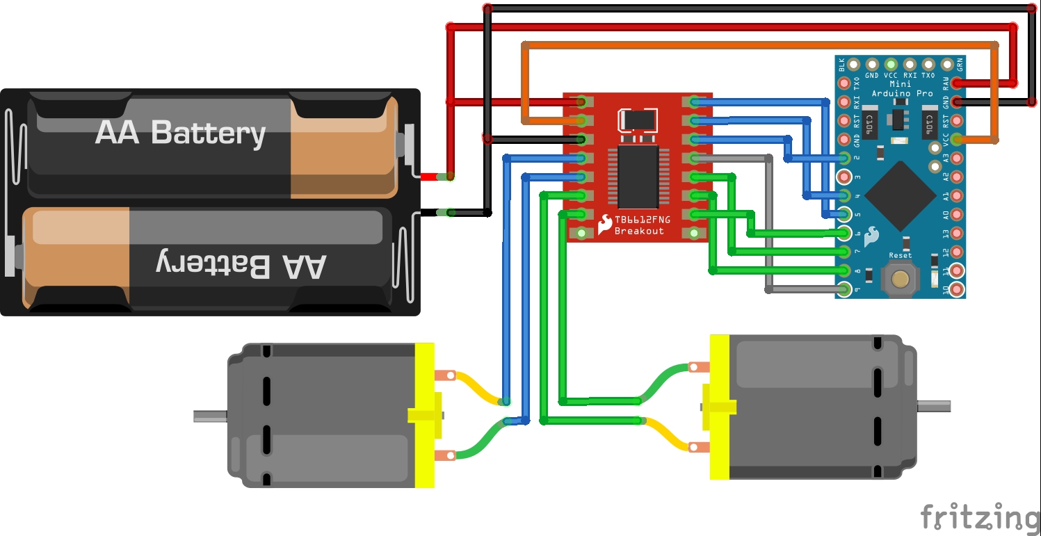
Here is a Fritzing diagram showing how all the connections were made.
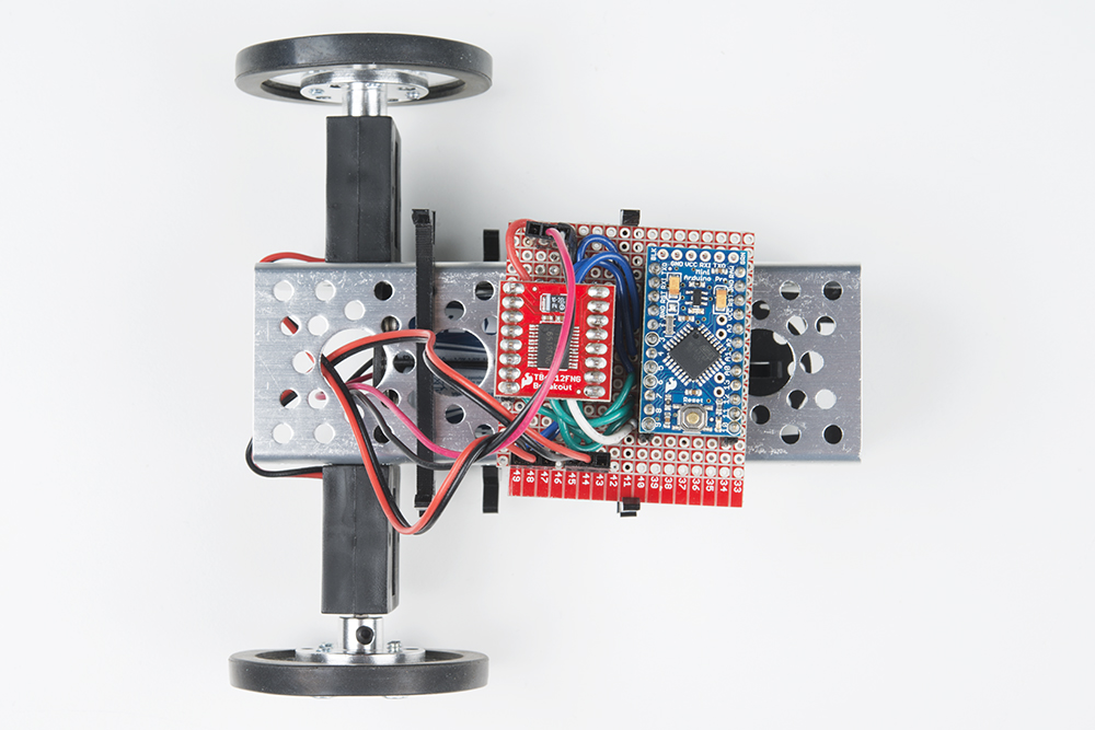
Here is the final project assembled on the Actobitty chassis.
Final step is uploading the code. First we must download and install the library. If you are unfamiliar with installing an Arduino library, check out our tutorial.
Download the library using the link below, or grab the latest version from our GitHub repository.
Once the library is installed, you can find the example code under File->Examples->TB6612, and upload the code to your Arduino. We'll get into the code in a minute. In the mean time, you can see it goes through a few basic commands to get you familiar with the library. Keep in mind, in the example code, each command has another command immediately after it that does the opposite and should bring it back to home should your robot should run too far away (I was able to run mine on a notebook without it falling off).
Here we have a basic library. There are two main parts. First, you can send commands like forward, and it will propel your bot forward. This means the right wheel is going clockwise and the left wheel is going counterclockwise. Which way is clockwise and which is counterclockwise depends on which wire of your motor is connected to which of the inputs. This means the forward function might not actually propel the robot forward the first time. You can swap the motor wires if you want, but that is often not possible. The easier solution is to fix this in the software. Near the top of the example code, you will see two constants labeled offset. You can change this from 1 to -1 to swap the configuration of that motor.
language:c
// these constants are used to allow you to make your motor configuration
// line up with function names like forward.  Value can be 1 or -1
const int offsetA = 1;
const int offsetB = 1;
The second part of the library is individual motor control. If you are not driving a robot, controls such as forward are not useful, and you probably don't want the two motors tied together like that. The library will let you make as many instances of motors as you want (or have memory for). This means if you have three TB6612FNGs, you can control six motors individually.
language:c
// Pins for all inputs, keep in mind the PWM defines must be on PWM pins
#define AIN1 2
#define BIN1 7
#define AIN2 4
#define BIN2 8
#define PWMA 5
#define PWMB 6
#define STBY 9
Looking at the example code you will see we start with a lot of defines. This is basically a spot to let you tell the code to which pins you hooked things up. As mentioned earlier you can also play with the constants to switch directions of the motors. Afterwards we initialize the motors, by sending those constants to the function Motor(). This initialization also takes care of all the pinModes. This actually leaves us with nothing to do in the setup function. We could give it a few commands we want to only do once, but we chose to put all the commands in the loop function.
language:c
void loop()
{
   //Use of the drive function which takes as arguements the speed
   //and optional duration.  A negative speed will cause it to go
   //backwards.  Speed can be from -255 to 255.  Also use of the
   //brake function which takes no arguements.
   motor1.drive(255,1000);
   motor1.drive(-255,1000);
   motor1.brake();
   delay(1000);

   //Use of the drive function which takes as arguements the speed
   //and optional duration.  A negative speed will cause it to go
   //backwards.  Speed can be from -255 to 255.  Also use of the
   //brake function which takes no arguements.
   motor2.drive(255,1000);
   motor2.drive(-255,1000);
   motor2.brake();
   delay(1000);

   //Use of the forward function, which takes as arguements two motors
   //and optionally a speed.  If a negative number is used for speed
   //it will go backwards
   forward(motor1, motor2, 150);
   delay(1000);

   //Use of the back function, which takes as arguments two motors
   //and optionally a speed.  Either a positive number or a negative
   //number for speed will cause it to go backwards
   back(motor1, motor2, -150);
   delay(1000);

   //Use of the brake function which takes as arguments two motors.
   //Note that functions do not stop motors on their own.
   brake(motor1, motor2);
   delay(1000);

   //Use of the left and right functions which take as arguements two
   //motors and a speed.  This function turns both motors to move in
   //the appropriate direction.  For turning a single motor use drive.
   left(motor1, motor2, 100);
   delay(1000);
   right(motor1, motor2, 100);
   delay(1000);

   //Use of brake again.
   brake(motor1, motor2);
   delay(1000);

}
Finally we hit our good friend loop(). Here is where we are testing out the different functions. As you can see some functions take our two motors as arguments like forward(motor1, motor2) and back(motor1, motor2), while other functions are part of the Motor class and are called using commands like motor1.drive(speed).
language:c
// Constructor. Mainly sets up pins.
Motor(int In1pin, int In2pin, int PWMpin, int offset, int STBYpin);

// Drive in direction given by sign, at speed given by magnitude of the
//parameter.
void drive(int speed);

// drive(), but with a delay(duration)
void drive(int speed, int duration);

//currently not implemented
//void stop();           // Stop motors, but allow them to coast to a halt.
//void coast();          // Stop motors, but allow them to coast to a halt.

//Stops motor by setting both input pins high
void brake();

//set the chip to standby mode.  The drive function takes it out of standby
//(forward, back, left, and right all call drive)
void standby();

//Takes 2 motors and goes forward, if it does not go forward adjust offset
//values until it does.  These will also take a negative number and go backwards
//There is also an optional speed input, if speed is not used, the function will
//use the DEFAULTSPEED constant.
void forward(Motor motor1, Motor motor2, int speed);
void forward(Motor motor1, Motor motor2);

//Similar to forward, will take 2 motors and go backwards.  This will take either
//a positive or negative number and will go backwards either way.  Once again the
//speed input is optional and will use DEFAULTSPEED if it is not defined.
void back(Motor motor1, Motor motor2, int speed);
void back(Motor motor1, Motor motor2);

//Left and right take 2 motors, and it is important the order they are sent.
//The left motor should be on the left side of the bot.  These functions
//also take a speed value
void left(Motor left, Motor right, int speed);
void right(Motor left, Motor right, int speed);

//This function takes 2 motors and and brakes them
void brake(Motor motor1, Motor motor2);
With that, you should have the basic knowledge to get started with your next motor-moving project. For more information on the TB6612FNG motor Driver, check out the links below.
For more great motor action, check out these other SparkFun tutorials.
Or check out some of these blog posts for ideas:
learn.sparkfun.com | CC BY-SA 3.0 | SparkFun Electronics | Niwot, Colorado