smôl Header Hookup Guide
 PaulZC
Hardware Overview
smôl boards are designed to stack one on top of the other, using 16-way 0.5mm-pitch Flexible Printed Circuits (FPCs). We really like FPCs and we're using them on more and more of our products. But they can be a bit tricky when it comes to prototyping or if you want to connect other devices to your smôl stack. The smôl Header is here to help!
FPC Connections
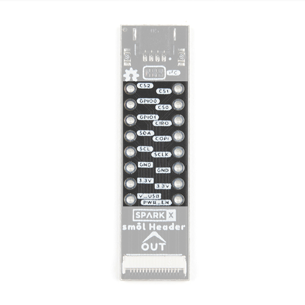
Like all of our smôl boards, the Header is equipped with a 16-way 0.5mm-pitch Flexible Printed Circuit connector. The pin-out for the smôl Header connector is as follows:
| Connector Pin No. | Signal Name | Function |
|---|---|---|
| 1 | PROC_PWR_EN | Processor Power Enable |
| 2 | 3V3 | 3.3V Power Rail |
| 3 | GND | Power Ground / 0V |
| 4 | SCLK | SPI Clock |
| 5 | COPI | SPI Controller Out Peripheral In |
| 6 | CIPO | SPI Controller In Peripheral Out |
| 7 | CS0 | SPI Chip Select 0 |
| 8 | CS1 | SPI Chip Select 1 |
| 9 | CS2 | SPI Chip Select 2 |
| 10 | GPIO0 | General Purpose Input / Output 0 |
| 11 | GPIO1 | General Purpose Input / Output 1 |
| 12 | SDA | I2C Data |
| 13 | SCL | I2C Clock |
| 14 | GND | Power Ground / 0V |
| 15 | 3V3 | 3.3V Power Rail |
| 16 | V_USB | USB Power Rail (5V) |
Breakout Pins
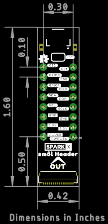
You've got full access to all the smôl pins, so connecting your favorite SPI board to smôl is as easy as plug-and-play! The smôl Header breaks out all 16 smôl connections in good old 0.1" format. The hole pattern is the same as an old school 16-pin 0.3" Dual-In line Package (DIP). Perfect for soldering header pins to and then pushing into standard breadboard.
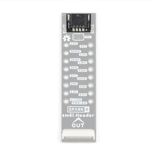
Qwiic Connector
We've included a Qwiic connector too, so you can attach your favorite Qwiic boards to your smôl stack qwiicly and easily.
Qwiic (I2C) Pull-ups
The Header also includes pull-up resistors for the I2C SDA and SCL signals. You can disconnect the resistors if required by opening the dual split-pad jumper links.
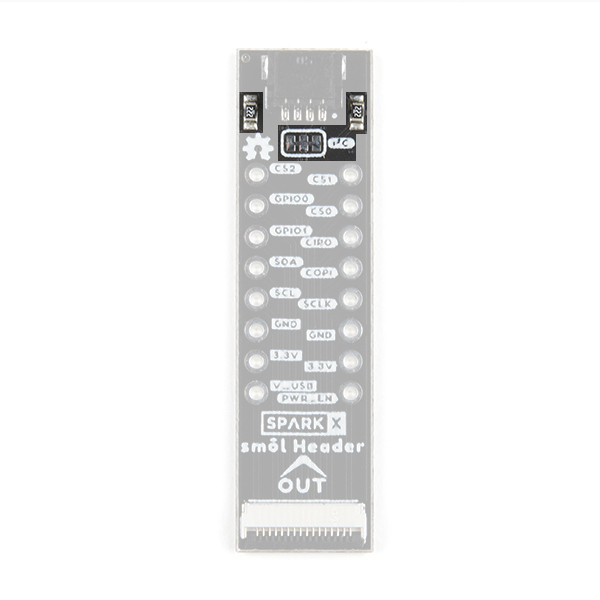
If you haven't used jumpers before, please check out our tutorial.