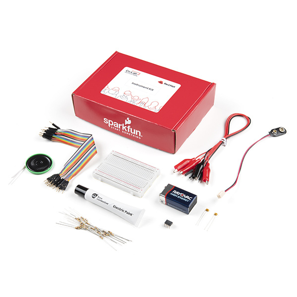
How can open source help us find new ways to express ourselves? In the Red Hat Instrument Kit, you'll learn how conductivity works and use that understanding to create an interactive musical instrument. Conductive paint and ink will allow you to explore how physical design affects the way a tool is used. This experiment empowers participants to bring their own creative thinking to the world of sound and instruments. This activity is best suited for people between the ages of 10-13 and does not require any prior knowledge of circuits or skill in wiring or electronics. Given that some of the components are small and making connections requires a level of dexterity, younger students may need some adult assistance.
To follow along with this tutorial, you will need the Red Hat Instrument Kit.
If you wish to purchase the individual parts for this as refill or expansion, here is a list:
You will need materials that didn’t come with your kit (paper and a pair of scissors).
If you are not familiar with the following concepts, we recommend checking out these tutorials before continuing.
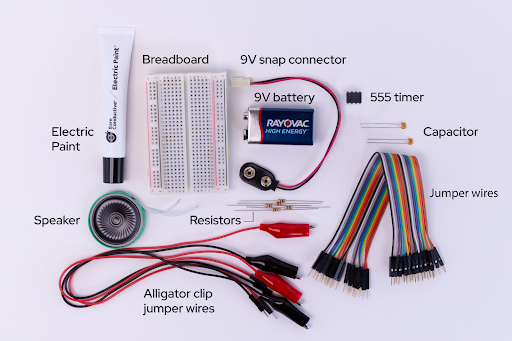
It’s always helpful to know the parts you will be using before diving into the build. Go ahead and lay the parts out in front of you on a piece of paper. As you lay them out, pick them up and explore each one. How many pins does it have? What colors are on it? Is each leg of the component the same length? Can you guess what it does, based on how it looks or what it's called? You should write these observations down next to each part. That will help you organize the pieces as we begin to explore and build. This is what you should have:
Let’s start by taking a look at the breadboard in your kit. First, notice there are two long columns of holes running down each side of the board, one with a red line beside it, and one with a black line. These are the power rails, and all the holes in a single power rail are connected to each other. If power is connected to one hole in the column, it is connected to all the other holes in the column.
Second, all the holes in a numbered row are connected to each other, but this connection is broken at the small trench or indent that runs down the center of the board. Each side COULD be its own separate circuit. Our project will jump over the trench using jumper wires and send power back and forth.
Basically, you can view a breadboard as a series of columns (labeled A-E and F-J) and rows (labeled 1-30.) And remember, the trench in the middle means A5 isn’t connected to F5. When we get to actually creating the circuit, we’ll use this row-and-column system to mark where connections should be made (A6, E3, H23, etc.).
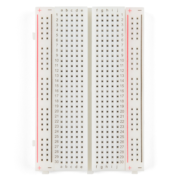
For more information on how to Use a Breadboard, feel free to head on over to our tutorial here, or click on the breadboard image below.
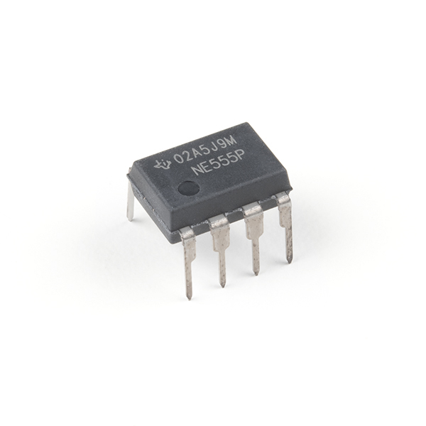
A 555 circuit’s use is so open-ended that contests are held to see who can conceive of the most useful, complex, and/or artistic use of the thing. Every sound we hear from an instrument is made of a waveform. The pitch (how high or low a note sounds to our ears) changes with the number of times a wave occurs in a second. With the 555 at the heart of our circuit, (and a handful of choice resistors and capacitors) we can create waveforms that oscillate at frequencies from thousandths to hundreds of thousandths of a second. That’s a lot of waves per second!
A capacitor is a two-terminal, electrical component. Along with resistors and inductors, they are one of the most fundamental passive components we use. You would have to look very hard to find a circuit which did not have a capacitor in it. What makes capacitors special is their ability to store energy; they are like a fully charged electric battery. Caps, as we usually refer to them, have all sorts of critical applications in circuits. Common applications include local energy storage, voltage spike suppression, and complex signal filtering.
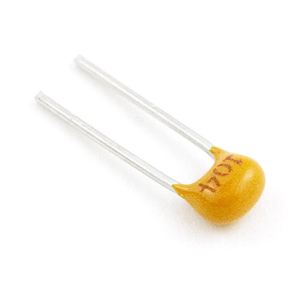
For more information on capacitors and their uses, feel free to head on over to our tutorial here, or click on the Capacitor image below.
This little guy is similar to what you'd find in one of those singing greeting cards. Thin and flat, and able to make just enough noise for our project.

Resistors are electronic components which have a specific, never-changing electrical resistance. The resistor's resistance limits the flow of electrons through a circuit.
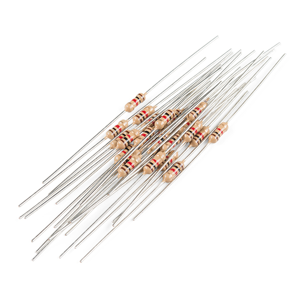
For a basic description, this is good enough, but if you would like to delve into the world of resistors and Ohm's law, consider checking out this tutorial or click on the image below:
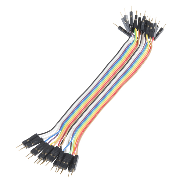
Jumper wires help a circuit "jump" from one location to another. Hence the name "jumper wire". Pretty nifty eh? The end ports can be male or female - in this tutorial you'll be using Male to Male jumpers, meaning both ends have plugs on them.
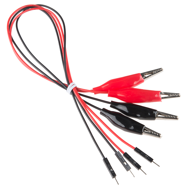
These guys are just like Jumper Wires, except that they are pre-terminated with an alligator clip on one end and a hookup pigtail on the other. Like so:
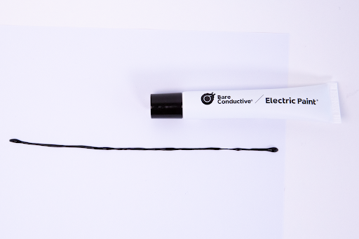
Bare Conductive's Electric Paint is just like any other water-based paint... except that it's electrically conductive. This means that you can actually paint wires onto things like models, clothes, furniture, walls, almost anything you can think of. In this case, we will be using it to draw our instrument. Check out the video below for more information on our conductive paint...
If that nifty little video didn't sate your need for information, see the datasheet for more in-depth info.
There are other parts in this kit, but this is the bulk of what you'll need to know for this tutorial. Let's get to building!
What is an instrument? This is kind of a weird question, right? Really, a musical instrument is anything you can use to produce sound. Guitars, gourds, seashells, pianos ― used the right way, they can all be instruments.
For the purposes of this kit, a musical instrument is a device that lets us make sounds and control their pitch ― how high or low they are. Using your conductive paint/ink, make a long line on your piece of paper. Be sure to draw at least one solid block of ink near the edge of the paper. You’ll be able to redesign your instrument later and be really creative in how it takes shape, but for now just make a thin line.
What is a circuit? A circuit is a closed loop that electricity can travel around. At its most basic, a circuit consists of three parts:
An example of a simple circuit would be a power source (like a battery), a load (like an LED), and the circuit path (the wires that connect them).
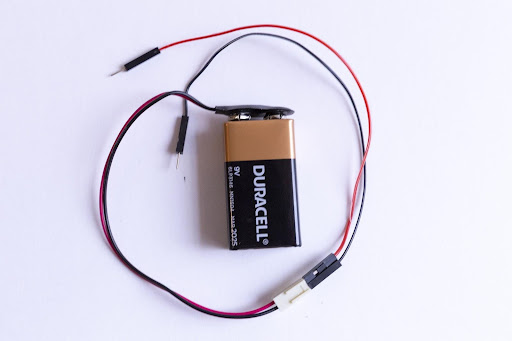
Your kit comes with a 9V battery and 9V snap connector to be used as a power/voltage source. You'll notice that the snap connector has a plastic connector ― the small, white, rectangular box at the end of the red and black wires. This makes it easy to connect to many types of electronics; however, we won’t be using it for our project today. We’ll actually connect the power to the breadboard with jumper wires. The jumper wires in your kit have small metal pins on either side.
The colors of the jumper wires don’t correspond to anything in your kit. Use any two colors that you prefer. That said, make sure you keep track of which jumper is positive and which jumper is negative. By convention, the red jumpers are positive, and the black jumpers are negative/ground.
There are two holes in the plastic molding at the end of the wires coming from the battery pack. Insert a jumper wire into each of these holes like so:
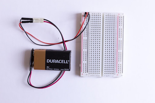
Now insert the other ends into the (+) power rail and the (-) power rail - again making sure that your positive jumper goes to the (+) side of the power rail and the negative jumper goes to the (-) side of the power rail:
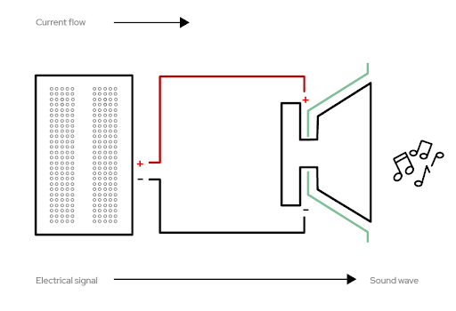
For this circuit, we will use a 555 circuit attached to a speaker triggered by a potentiometer. Potentiometers can take multiple shapes. Sometimes, we might see them as knobs that we turn, like volume knobs on radios. Other times, they look like faders that slide up and down; think of some dimmable light switches. They can give us control over things like speed, voltage, or frequency in our circuit kits. As we make adjustments to our knob or fader, we are changing the amount of resistance that a circuit is passing.
For our circuit, we’ll draw our potentiometer using conductive paint or ink. Since we know that circuits are continuous devices, we’ll have to make sure that, whatever instrument we draw, all the lines connect somehow. The ink we used to draw our line above will serve as our potentiometer.
Our circuit culminates in the speaker. If you’ve used headphones or earbuds, or watched TV, you have a pretty good idea what speakers are capable of. For our purposes, the speaker converts the electrical audio signal (in the form of sound waves) from our 555 timer into sound. This is the same basic principle that a guitar amplifier or movie theater sound system uses.
For a circuit to work, the path of the power can’t be interrupted — every piece must connect with another piece. Luckily, we have a breadboard, which is a helpful tool we can use to quickly plug in items and keep them connected. It also lets us create, fix small mistakes, and practice with our components.
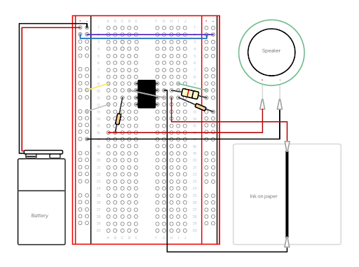
We are going to replicate this circuit (the steps are below). We’re using quite a few jumper wires, so be extra careful to place them into the appropriate coordinate points on your breadboard. We’ll save the special alligator clip connections for last. We’ll use both sides of our breadboard, so remember that each side has a positive (+) and negative (-) power rail, as well as its own unique set of column connections. The left hand columns are labeled A-E, and the right hand columns are F-J.
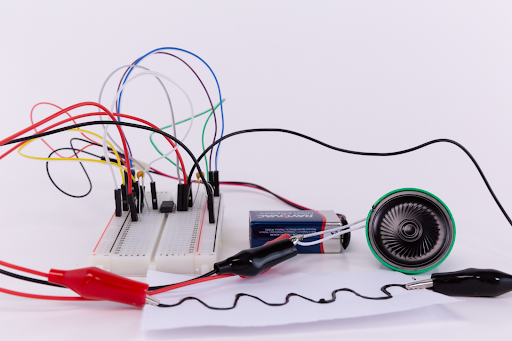
Once you complete the steps above and place the battery into the pack, you can play the ink like an instrument! To test your build, simply take the loose end of the final alligator clip jumper wire and tap it against any part of the conductive ink/paint line.
Now that you see how the system works, take some time to redesign your instrument any way you want. Just remember that it’s best to have a small block of conductive ink on the edge of your piece of paper to anchor the clip to. After you redesign your instrument, all you have to do is reclip the alligator wire that was previously on the edge of your paper with the straight line to the edge of the paper with the new instrument. Tap away!
Here are some things to look for if your project isn't working. Also, ScienceBuddies.org has a great exploration of common mistakes people make with breadboards.
Sometimes, things break or get lost ― it's part of making and tinkering. If you need to replace a part, refer to the wishlist in the introduction of this guide to purchase any individual components that make up the Red Hat Co.Lab Instrument kit that you might need.
After you’ve built your instrument, check out the Red Hat Open Source Stories film, Art of Exchange. This film shows the role open source plays in the shaping and sharing of new ideas.
Want more? Check out additional Red Hat Co.Lab kits at red.ht/colab-kits.
learn.sparkfun.com | CC BY-SA 3.0 | SparkFun Electronics | Niwot, Colorado