Industrial Fiber Optics Hookup Guide
 Nick Poole
Getting Started with Fiber Optics
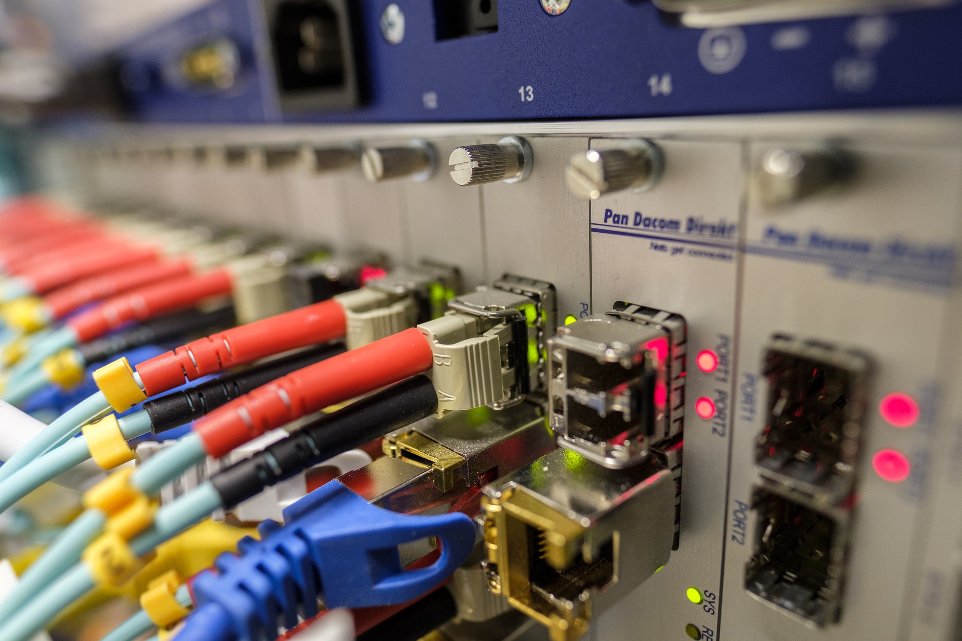
Copper is soooo last year. Haven’t you heard? All of the cool kids are transmitting their data over optical fiber with flashes of light! Okay, so fiber optics aren’t going to replace all copper wires any time soon, but they are hard to beat in some situations. For instance, long fiber optic lines don’t act as antennas that introduce noise to your circuit. They also won’t transmit power surges from things like ground faults or lightning strikes. What’s more, they don’t interfere with sensitive RF equipment that might be otherwise disturbed by the EMF radiation from electrical signalling.
Historically, however, fiber has also had some disadvantages. Optical fiber can be fragile and expensive. The connectors can be hard to install and often require specialized tools. Cutting and splicing fiber can entail quite a lot of work, including polishing all of the interfaces for optimal transmission. On top of that, the modems on either end are often expensive and designed for a very particular application. But what if I told you there was an affordable, generic fiber solution that requires no specialized connectors or polishing equipment? And what if I told you that it could easily achieve 1Mbps over hundreds of meters of cable? Well this is exactly what I’m telling you.
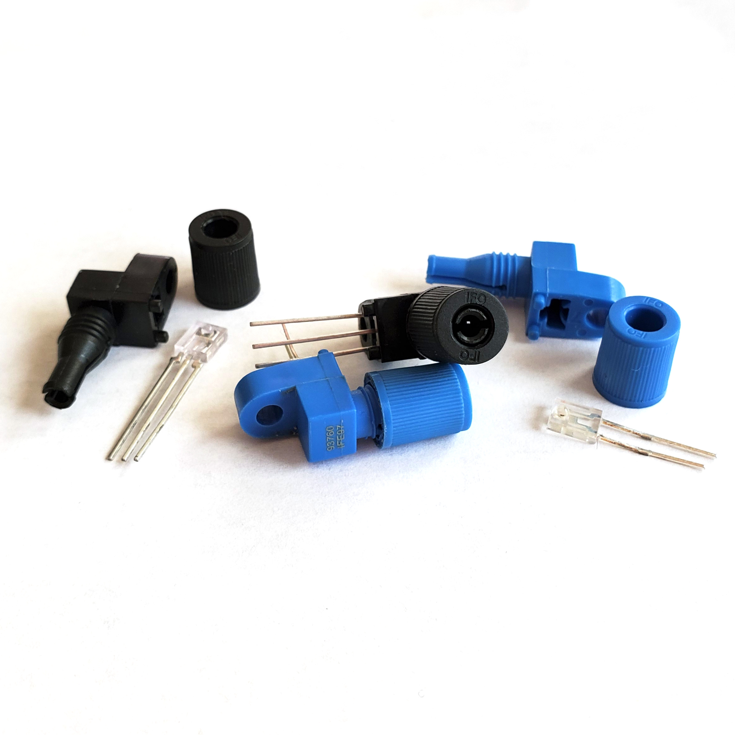
The Industrial Fiber Optics line of emitters and detectors are by far the most economical way we’ve found to create a simple fiber link between two devices. The IF-E97 emitter is literally just a superbright red LED in a fancy plastic module that makes it easy to insert a piece of optical fiber and lock it in place. On the other end, the IF-D96F is a 5v TTL phototransistor in an identical enclosure. Connect the two with a piece of fiber and you have, basically, the simplest possible fiber link. Speaking of fiber, while you can certainly use glass fiber (in the proper jacket) to connect these modules together, we recommend PMMA plastic fiber! It’s cheap, it’s not at all fragile, and you can cut it with scissors. In our experience, it requires no polishing at all, simply cut it with scissors and jam it into the connector.
So are you sold on Industrial Fiber Optics’ general purpose receivers and transmitters? Great, because we’ve designed three different products to help you incorporate them into your next project…
Serial Fiber Modem
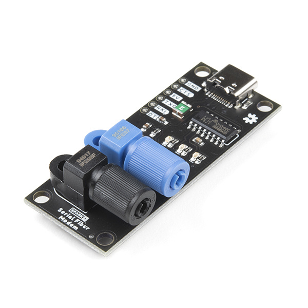
The Serial Fiber Modem combines a USB-to-Serial bridge with a fiber receiver and transmitter and is the easiest way to start playing with fiber right out of the box.
Serial Fiber Modem
SPX-17508To get started, use a USB-C cable to connect the Serial Fiber Modem to your computer. It will enumerate as a serial device the same way as our Serial Basic Breakout. The board has one transmitter and one receiver, so it acts as one side of a full duplex link. However, if you just want to test your board, you can create a simple loopback by inserting a piece of fiber optic cable into the transmitter and receiver of the same board.
A Note About Plastic Fiber
These modules are designed to accommodate simplex fiber optic cable with a jacket diameter of 2.2mm, which is commonly available online from several manufacturers. We carry 1 meter lengths of plastic core fiber cable to get you started.
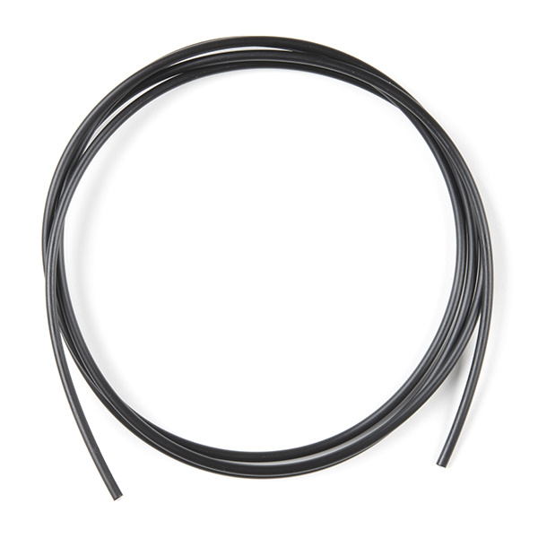
The cable that we sell contains a single 960µm PMMA core with a fluorinated polymer cladding that brings it to 1000µm, and finally a polyethylene jacket that measures 2.2mm in diameter. It is easily cut with a pair of sharp scissors. The cut end requires no polishing in most applications. When cutting the cable, make the cut as perpendicular to the end as possible to create a flat optical surface. There is no need to “strip” any part of the jacket, simply cut it flush with the core.
To insert the cable into the module, first loosen the locking nut and then simply push the cut end of the fiber cable as far into the module as possible. After inserting the cable, tighten the locking nut “finger-tight,” so that the cable cannot easily be tugged free from the module. Careful not to overtighten, as the plastic threads are easy to damage.
Once a piece of fiber is installed between the receiver and transmitter, simply open a serial terminal and start typing. You should see that your text is being transmitted and then received and displayed in the terminal. In our experience, text could be transmitted without error at baud rates up to 1M over at least 50 meters of fiber.
When connecting two Serial Fiber Modems to each other, be sure to connect the transmitter of one board to the receiver of the other and vise-versa (blue to black and black to blue)
Fiber Duplex Breakout
We designed the Fiber Duplex Board for creating simple fiber links to embedded devices. This board has the same pinout as our Serial Breakouts, so they will connect directly to the serial header of many dev boards such as the Arduino Pro or Pro Mini.
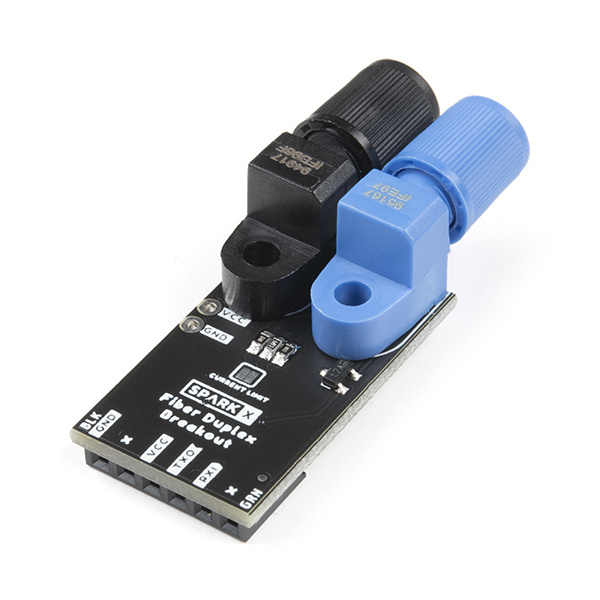
Fiber Duplex Breakout
SPX-17510To create a fiber link between two dev boards, simply connect the Fiber Duplex Breakout to each board, connect them with two pieces of fiber cable, and then use the Serial library to send and receive data as you normally would.
This board also works in concert with the Serial Fiber Modem to create a fiber link from a dev board to a computer. We’ve even had success loading Arduino code over fiber this way (although because the fiber doesn’t carry a DTR signal, we had to manually reset the Arduino board during upload)
What is the CURRENT LIMIT Jumper?
This jumper can be found on both the Fiber Duplex and Simplex Breakouts. Because the boards will operate at both 3.3V and 5V, this jumper is provided to halve the current limiting resistance to the transmitter LED. In most cases, you’ll never need to close this jumper because the LED will simply operate at 3.3V with reduced brightness. If you’re having trouble transmitting over a long distance at 3.3V, however, closing this jumper will allow the LED to operate at it’s full rated current.
Resources
So that's it, putting your Arduino on fiber can be fun and easy! In the comments, I'd love to hear what application you have in mind for these boards. For your convenience, here are datasheets for the Industrial Fiber Optics parts as well as the plastic fiber that we carry:
Also, it can be helpful to brush up on the basics of serial communication if you're going to be building and troubleshooting serial links. Here's our tutorial on the subject:
Serial Communication
Happy Hacking!