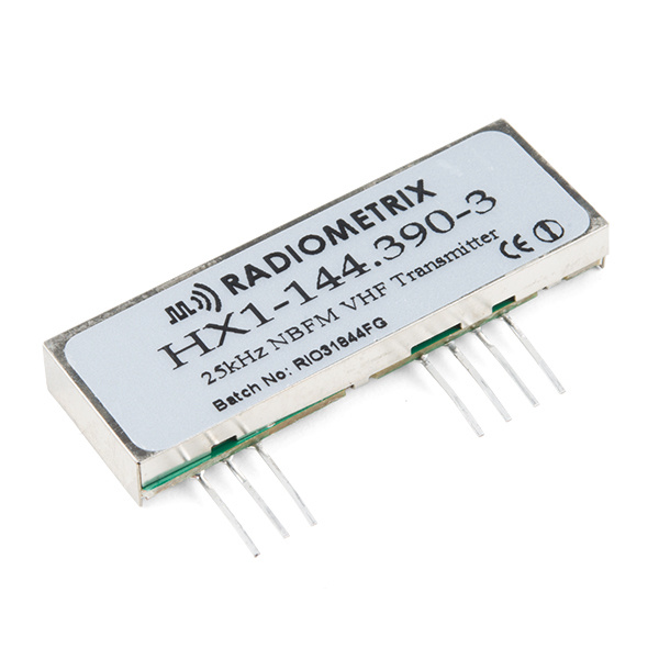
The HX1 is a low-power radio transmitter set to a fixed frequency of 144.390MHz. In North America this frequency is used for the Automatic Packet Reporting System, or APRS.
APRS is a standard used by amateur-radio operators to broadcast location and sensor data. This data can be received by anyone with the proper equipment, and is aggregated on the internet through gateways run by the APRS community.
APRS is used to share real-time data including vehicle location (GPS), weather stations, high-altitude balloon tracking, remote sensor platforms, disaster relief coordination, and more. It’s effectively an open-source, open-data, community-run, free to use, IoT system with potentially worldwide coverage.
To follow along with this guide, you will need the following materials.
Before we go too much further, we'll remind you that since this transmitter uses an amateur radio frequency, you will need an amateur radio license to operate it. Don't worry; getting a license is easy and opens you up to a whole new world of technical capabilities.
The most basic license class, Technician, will be sufficient to use this transmitter. You'll need to pass a 35-question test, and the entire pool of questions and answers is available beforehand for you to study. If you've been playing with electronics for a while and know Ohm's Law (V=IR), you're halfway there. The rest involves memorizing some straightforward rules and regulations.
The first step is to go to the American Radio Relay League (ARRL) website. The ARRL is the amateur radio community organization. Even though your license will be issued by the Federal Communications Commission (FCC), the ARRL handles training and testing. At the ARRL website you'll find a list of upcoming exam sessions near you, as well as practice questions and other useful information.
Once you pick an exam date and location, study! In addition to the ARRL website, there are a number of books, websites, and apps that can help you study. On test day, show up with the required fee, a photo ID, a #2 pencil, and a nonprogrammable calculator (phones aren't allowed). When you finish the test, the examiners will tell you immediately whether you passed or not. If you passed, you'll get your callsign in the mail in a few weeks. And once you have your callsign, you can legally transmit with the HX1 (as well as do many other things).
APRS was conceived in the 1980s by Bob Bruninga (WB4APR), currently a senior research engineer at the United States Naval Academy and still very active in the APRS community. It filled a need for a simple way to transfer small amounts of textual data between multiple amateur radio stations without having to manually copy voice messages. APRS has since evolved into a rich, global system for transmitting location and sensor values that others can receive and use.
Speaking of receiving, if the HX1 is just a transmitter, how does one receive APRS messages?
You can easily receive APRS packets with the proper equipment. An inexpensive 2-meter receiver tuned to 144.390MHz will receive the audio tones that make up APRS packets. You can then pipe the audio to a computer running the proper software to decode the packets. You can then use the information in the packets to display locations on a map, graph other data included in the packets, etc.
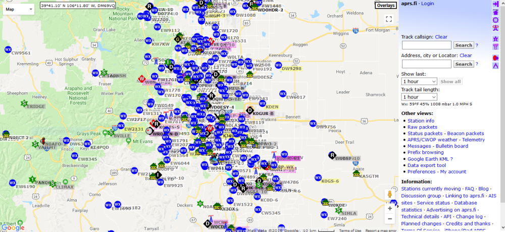
But you don't necessarily have to set up your own receiver. Many people in the APRS community have already set up receiving stations, called "gateways," that receive APRS packets and pipe the data onto the internet for aggregation by various websites. One of the largest websites is APRS.fi. It receives live APRS data from all over the world, displaying station locations and data on a map. (If you become an enthusiast of APRS, you're encouraged to set up your own gateway and join the network.)
An APRS "packet" is a short (25 to 200 characters), self-contained text message. APRS has strict formatting rules, with fields for various types of data (station callsign, GPS location, time, weather data, etc.). Because the formatting is standard, packets generated with one software package can be received and decoded by everyone else. Formatting details are available in the APRS Spec available at APRS.org.
Because APRS uses a single shared frequency (in North America it's 144.390MHz), everyone can see what everyone else is doing. By keeping the packets short and turning off transmitters between sends, many people can share the same frequency. Packets are often sent at slightly random times to avoid packet collisions (two people transmitting at the same time). If there are collisions the data for both packets is garbled. However, APRS systems are normally set to resend new packets every few minutes, guaranteeing fresh data before too long.
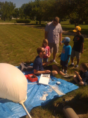
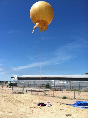
If you go to APRS.fi and look at the live map, you'll see the current locations of vehicles, aircraft, and sometimes high-altitude balloons. You'll also see fixed weather stations and other environmental sensors. These transmissions are all being made by people who have a personal or hobbyist use for various data (such as vehicle or balloon locations), or who want to provide useful data to the larger community (such as a weather station at their house).
It's worth noting that since APRS uses amateur radio frequencies, the transmissions must abide by the rules and spirit of the amateur radio community. Specifically:
Amateur radio frequencies are solely for non-commercial use. You can use APRS for your own hobby or scientific use, but you can't use APRS for any part of a business. (Amateurs are very serious about this - radio bands are a valuable commodity, and amateurs regularly have to fight to keep what they have from being sold to commercial bidders.)
The data you send must be open. Since you're transmitting on an open system everyone can see your data, but you're not allowed to hide it by encrypting or obscuring it. Along these lines, it's encouraged that the data you send be of interest to the community - weather stations and other public-service data sources are always appreciated.
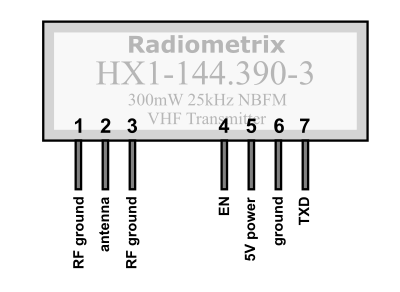
The HX1 has seven pins in two groups:
| Pin | Function | Notes |
|---|---|---|
| 1 | RF Ground | Antenna ground or coax shield |
| 2 | Antenna Output | Antenna or coax center |
| 3 | RF Ground | Antenna ground or coax shield |
| 4 | EN (Enable) Input | 5V to transmit, 0V for standby |
| 5 | 5V Power Input (VCC) | Regulated 5V power supply at 140mA |
| 6 | Ground | Ground of regulated power supply |
| 7 | TXD (Transmit Data) Input | 5V signal with modulation and formatting |
The HX1 requires a regulated 5V supply capable of providing 140mA when it's transmitting (it uses essentially no current in standby). The voltage regulator already present on a 5V Arduino should be able to handle this.
The EN or enable pin controls whether the module is transmitting or in standby mode (sometimes this is called a PTT or "Push To Talk" control). Since APRS uses a shared frequency, it's important to only transmit during the brief time that a packet is being sent and stay silent otherwise; this lets many people share the frequency. To transmit, the EN pin must be set to a high logic level (5V).
After enabling the transmitter, it's a good idea to wait 5ms before sending any data to the TXD pin. Your software should handle this automatically.
It's important to note that the HX1 is a bare transmitter and doesn't do any modulation or packetizing on its own. The TXD data input must be modulated properly in order to transmit properly. Modulation and packetizing is a broad topic beyond the scope of this tutorial, but there are several Arduino projects designed to connect to the TXD pin of the HX1 and send data. We'll cover one of these projects below.
The HX1 requires an antenna to transmit. You can buy one (search for "2 meter antenna" as the APRS frequency is in the 2-meter amateur radio band), or you can build one.
There are many antenna designs out there, but a simple quarter-wave ground plane antenna works well and is easy to make. This antenna features a vertical element surrounded by four radial elements angled down at 45 degrees:
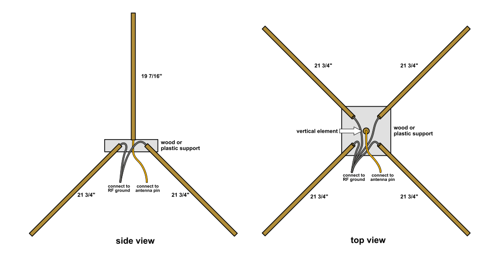
The length of an antenna's elements depends on the frequency. For the 144.390MHz frequency we'll be using, the element lengths are:
| Antenna | Length | |
|---|---|---|
| Vertical Element (1x): | 19 + 7/16" | 493mm |
| Radial Elements (4x): | 21 + 3/4" | 553mm |
The elements can be made of any conductive metal, but brass and copper rods are easy to solder to. The rods can be supported in position by any nonconductive material (plastic, wood, etc.).
To connect the antenna to the HX1, connect the vertical element to the antenna output pin (2), and the radial elements to the RF ground pins (1,3) on either side of the antenna pin.
If the HX1 transmitter will be more than a couple inches away from the antenna, use 50-ohm coaxial cable to connect the RF pins to the antenna. Connect the antenna output pin (2) to the center conductor of the coax, and the outer RF ground pins (1,3) to the shield. On the antenna side, connect the center conductor to the vertical element, and the shield to the radial elements or ground plane.
For maximum range, locate your antenna as high as practical and away from nearby metal objects PVC pipe is a good nonconductive structural material for this.
Note that this antenna design is omnidirectional, which means that it will work equally well in all directions, but it will have a somewhat reduced range. Directional antennas will give you greater range, but you'll need to point them towards the remote receiver. Amateur radio books and websites have information on many other antenna designs; check them out if you're interested.
Note: This example assumes you are using the latest version of the Arduino IDE on your desktop. If this is your first time using Arduino, please review our tutorial on installing the Arduino IDE. Make sure the included header files are in the same folder in order for the trackuino.ino sketch to compile.
Several open-source Arduino APRS projects are available, with various features and limitations. Here we'll present a project called Trackuino written by Javi Martin. Trackuino is a combination of hardware and software used to track high-altitude balloons. It's a bit older, but probably the easiest Arduino APRS implementation to use with the HX1.
A default Trackuino system includes a GPS receiver, two temperature sensors, a battery voltage sensor, and a buzzer (used to locate balloons when they land). To wire up the default system, use the following wiring diagram and table. (We'll discuss modifying the default system in the next section.)

| From | To | Description |
|---|---|---|
| HX1 VCC (5) | Arduino 5V | HX1 power supply |
| HX1 GND (6) | Arduino GND | HX1 power ground |
| HX1 EN (4) | Arduino D4 | HX1 transmit enable |
| HX1 TXD (7) | Arduino D3 | HX1 transmit data |
| HX1 RF ground (1) | Antenna ground | Antenna ground plane |
| HX1 antenna output (2) | Antenna | Antenna |
| HX1 RF ground (1) | Antenna ground | Antenna ground plane |
| GPS TX | Arduino D0 (RX) | GPS data |
| GPS power | Arduino 3.3V | GPS power |
| GPS ground | Arduino ground | GPS ground |
| Internal TMP36 power | Arduino D6 | Temperature sensor power |
| Internal TMP36 signal | Arduino A0 | Temperature sensor signal |
| Internal TMP36 ground | Arduino ground | Temperature sensor ground |
| External TMP36 power | Arduino D7 | Temperature sensor power |
| External TMP36 signal | Arduino A1 | Temperature sensor signal |
| External TMP36 ground | Arduino ground | Temperature sensor ground |
| Buzzer power | Arduino D9 | Buzzer power |
| Buzzer ground | Arduino ground | Buzzer ground |
| Arduino VIN (battery voltage) | Arduino A2 via 10k resistor | Battery voltage sensor |
| Arduino A2 | Arduino ground via 3.3k resistor | Battery voltage sensor |
Out of the box, Trackuino is configured for use on high-altitude balloons, but with a little hacking you can alter it for your own purposes.
There's one change you must make: open the config.h file, and insert your callsign and station ID at line 42. APRS transmits your callsign in every packet; this is a legal requirement.
Another thing you may want to change in the file aprs.cpp is the "symbol" character defined on line 62. This controls what graphical symbol will show up at your location when you're using APRS mapping software or websites. The provided 'O' indicates a balloon, but there are many other symbols available such as '-' for fixed location, 'K' for school, '>' for car, 'Y' for boat, etc. For a complete list, check out the link below.
By default Trackuino sends an APRS packet that includes GPS time, GPS location, altitude, battery voltage, and several temperature sensor values. If you want to build your own APRS packet, you can alter the aprs_send() function in aprs.cpp to remove various sensor values or add your own.
Once you have the hardware and software set up, run Trackuino. This should should begin transmitting APRS packets after it obtains a GPS lock.
If you have a 2-meter receiver or SDR, you can set it to 144.390MHz to hear the packets being sent. If you pipe the audio to a computer and run the proper software (Dire Wolf is one such package), you'll be able to decode the packets and see the original text.
If you are close enough to an APRS gateway, your packets will be received and piped to the internet. You should be able to go to APRS.fi and search for your callsign to see received packets and the data they contain.
There is a great deal of information about APRS on the internet. One can build antennas, run gateways, track balloons, help coordinate disaster relief, etc. Even the sky isn't the limit, as many amateur satellites receive and transmit APRS packets.
SparkFun will also be updating this and other tutorials as we work on APRS and other amateur radio projects. Get licensed, and stay tuned!
Now that you've successfully got your HX1 APRS Transmitter up and running, it's time to incorporate it into your own project!
For more information, check out the resources below:
Need some inspiration for your next project? Check out some of these related tutorials:
Looking for more information about high altitude balloon projects? Check out some of these related tutorials:
 |
 |
| Nate's High Altitude Balloon Series | Aaron's High Altitude Balloon Launch |
Or check out this related blog post:
learn.sparkfun.com | CC BY-SA 3.0 | SparkFun Electronics | Niwot, Colorado