How to Use a Multimeter
This Tutorial is Retired!
This tutorial covers concepts or technologies that are no longer current. It's still here for you to read and enjoy, but may not be as useful as our newest tutorials.
 Nate
Nate 
Continuity
Continuity testing is the act of testing the resistance between two points. If there is very low resistance (less than a few Ωs), the two points are connected electrically, and a tone is emitted. If there is more than a few Ωs of resistance, than the circuit is open, and no tone is emitted. This test helps insure that connections are made correctly between two points. This test also helps us detect if two points are connected that should not be.
Continuity is quite possibly the single most important function for embedded hardware gurus. This feature allows us to test for conductivity of materials and to trace where electrical connections have been made or not made.
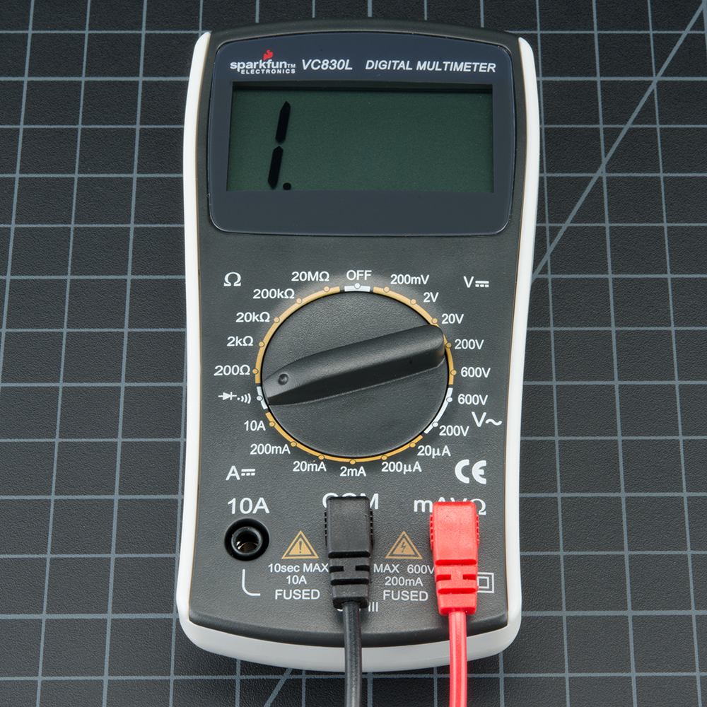
Set the multimeter to 'Continuity' mode. It may vary among DMMs, but look for a diode symbol with propagation waves around it (like sound coming from a speaker).
Now touch the probes together. The multimeter should emit a tone (Note: Not all multimeters have a continuity setting, but most should). This shows that a very small amount of current is allowed to flow without resistance (or at least a very very small resistance) between probes.
On a breadboard that is not powered, use the probes to poke at two separate ground pins. You should hear a tone indicating that they are connected. Poke the probes from the VCC pin on a microcontroller to VCC on your power supply. It should emit a tone indicating that power is free to flow from the VCC pin to the micro. If it does not emit a tone, then you can begin to follow the route that copper trace takes and tell if there are breaks in the line, wire, breadboard, or PCB.
Continuity is a great way to test if two SMD pins are touching. If your eyes can't see it, the multimeter is usually a great second testing resource.
When a system is not working, continuity is one more thing to help troubleshoot the system. Here are the steps to take:
- If the system is on, carefully check VCC and GND with the voltage setting to make sure the voltage is the correct level. If the 5V system is running at 4.2V check your regulator carefully, it could be very hot indicating the system is pulling too much current.
- Power the system down and check continuity between VCC and GND. If there is continuity (if you hear a beep), then you've got a short somewhere.
- Power the system down. With continuity, check that VCC and GND are correctly wired to the pins on the microcontroller and other devices. The system may be powering up, but the individual ICs may be wired wrong.
- Assuming you can get the microcontroller running, set the multimeter aside, and move on to serial debugging or use a logic analyzer to inspect the digital signals.
Continuity and large capacitors: During normal troubleshooting. you will be probing for continuity between ground and the VCC rail. This is a good sanity check before powering up a prototype to make sure there is not a short on the power system. But don't be surprised if you hear a short 'beep!' when probing. This is because there is often significant amounts of capacitance on the power system. The multimeter is looking for very low resistance to see if two points are connected. Capacitors will act like a short for a split second until they fill up with energy, and then act like an open connection. Therefore, you will hear a short beep and then nothing. That's ok, it's just the caps charging up.