$8.95
The SparkFun Qwiic AP3012K 5V Boost converts the logic-level and boost the voltage or power supply of the Qwiic connect system from 3.3V, to 5V on its PTH pins. This is handy for connecting any I2C device that requires a higher supply voltage, such as super bright LEDs or mechanisms like a DC fan on our air quality sensors. On the board, we also provide 3V3/5V jumpers, which can be used to configure the logic-levels of the I2C PTH pins. Therefore, this board can be utilized to connect an I2C device that requires any combination of 3.3V/5V for its power and/or signals.
The boost circuit on this board is rated to source up to a 100mA at 5V output, with 90% efficiency. However, users should note that this limitation is not only dependent on the load being connected, but also the amount of current that is being sourced to the Qwiic connector system.
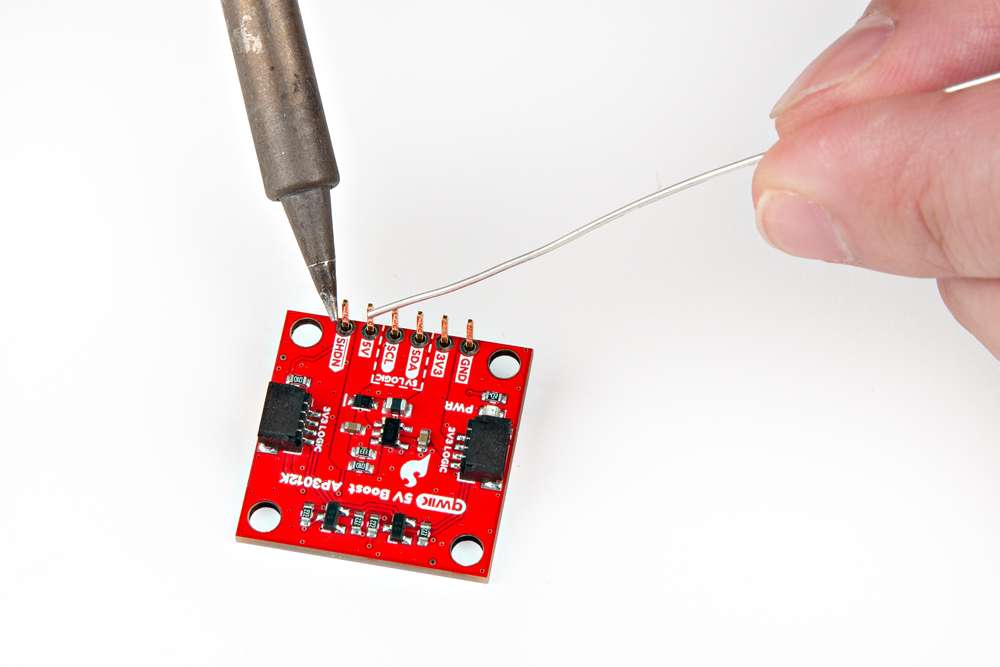
Attention: Soldering is required for this board.
In this guide we'll cover the hardware and how to utilize the Qwiic 5V Boost with the Sensirion SEN55 Sensor (but you can use the SEN54 or SPS30, instead). To follow along with this tutorial, users will need the following items:
Attention: Again, soldering is required for this board.
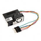
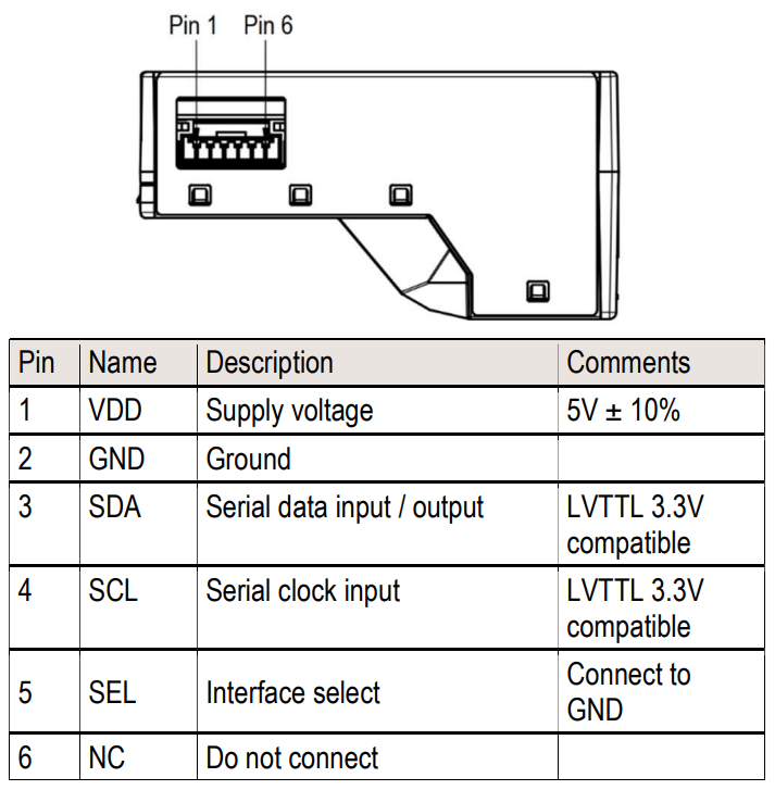
Tip: The Sensirion SEN55 Sensor requires an extra GND connection to enable the I2C interface.
Note: The These other Sensirion particulate matter sensors, may also be used in place of the SEN55:
This guide contains two main sections: Hardware Assembly and Quickstart Guide sub-sections.
If you are looking for the full Hookup Guide for the SparkFun Qwiic 5V Boost - AP3012K, click the button bellow. This basic tutorial only covers utilizing this Qwiic AP3012K 5V Boost to attach a SEN55 sensor to our Qwiic connect system.
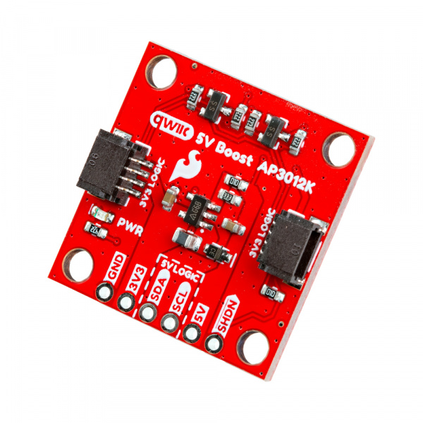
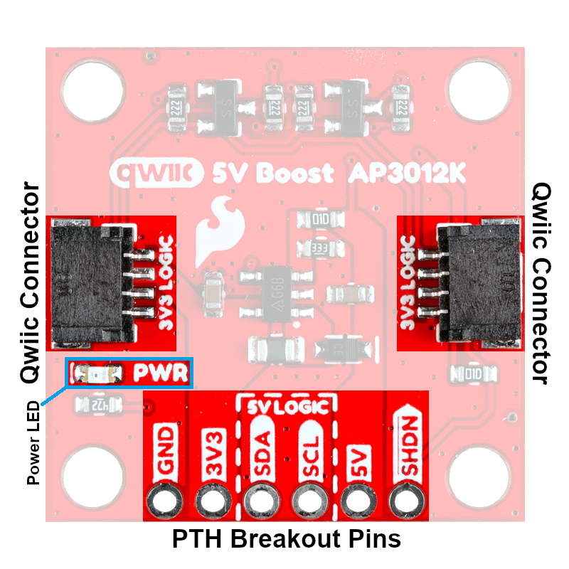
The PTH pins on the Qwiic 5V Boost are broken out into six 0.1"-pitched pins on the edge of the board. These pins are used to connect a 5V I2C device to the Qwiic connect system.
| Headers are versatile option testing and development. | Users can also connect a device directly to the board. |
 |
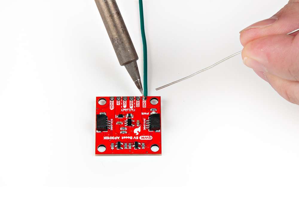 |
| Soldering headers to the Qwiic 5V Boost. | Soldering wires to the Qwiic 5V Boost. |
Tip: If you have never soldered before or need a quick refresher, check out our How to Solder: Through-Hole Soldering guide.
Configuration Options: With the 3V3/5V jumpers to configure the logic-levels of the I2C PTH pins, users can convert the power and logic-levels of the Qwiic connector to any combination of 3.3V and/or 5V on the PTH pins. Users will have the following options for connecting a device to the Qwiic 5V Boost:
| Output Power | 5V | 5V | 3.3V |
| I2C Logic-Level | 3.3V | 5V | 5V |
| Power Supply | Logic-Level |
| Use either the 5V or the 3V3 PTH pins to supply 5V or 3.3V power to the device. | Users can modify the 3V3/5V jumpers to configure the logic-level for the SDA and SCL PTH pins.
|
By default, the pins are configured to a 5V logic-level.
The simplest method to connect the Qwiic 5V Boost board to a microcontroller and/or other Qwiic devices, is through the Qwiic connector.
Tip: The intended design of the Qwiic 5V Boost board was to be utilized with the Qwiic connector system. However, the Qwiic 5V Boost can also be utilized with other interfaces, similar to how the SparkFun Logic Level Converter - Single Supply operates. The only difference is its TTL conversion, which is push-pull and not open-drain.
This is the basic layout of the Qwiic 5V Boost board.
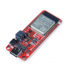
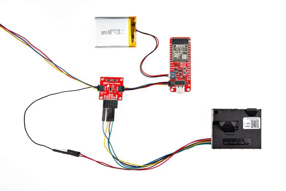
In this demo, we'll connect the Sensirion SEN55 particulate matter, VOC, NOx, humidity, and temperature sensor to the Qwiic 5V Boost board; and read data from it with an ESP32 Thing Plus development board, utilizing the Arduino IDE.
Soldering is required to connect the SEN55 sensor to the Qwiic 5V Boost board. In the example below, we used headers and a Qwiic jumper cable to make the necessary pin connections shown in the tables.
| Qwiic 5V Boost | Sensirion SEN55 Sensor |
GND |
2 |
5V |
1 |
SDA |
3 |
SCL |
4 |
GND |
5 |
Once the sensor is attached, users will need to connect the Qwiic 5V Boost board to their development board with a Qwiic cable.
Tip: If you're not familiar with using breakout board or soldering, please refer to the Hardware Overview & Assembly sections in the full Hookup Guide for a detailed overview of the board along with instructions on soldering to the breakout.
With the hardware assembled, users will need to program their development board to retrieve data from the SEN5X sensor. In the Arduino IDE, upload the exampleUsage example sketch from the Sensirion I2C SEN5X Arduino library. This example will read the particulate matter, VOC, NOx, humidity, and temperature values from the SEN5X sensor and output them in the Serial Monitor.
Follow the steps below to upload the example code:
Tip: If you're not familiar with using the Arduino IDE, refer to the Troubleshooting Tips section for related tutorials.
exampleUsage.ino Example Sketch
/*
 * I2C-Generator: 0.3.0
 * Yaml Version: 2.1.3
 * Template Version: 0.7.0-112-g190ecaa
 */
/*
 * Copyright (c) 2021, Sensirion AG
 * All rights reserved.
 *
 * Redistribution and use in source and binary forms, with or without
 * modification, are permitted provided that the following conditions are met:
 *
 * * Redistributions of source code must retain the above copyright notice, this
 *   list of conditions and the following disclaimer.
 *
 * * Redistributions in binary form must reproduce the above copyright notice,
 * *   this list of conditions and the following disclaimer in the documentation
 *   and/or other materials provided with the distribution.
 *
 * * Neither the name of Sensirion AG nor the names of its
 *   contributors may be used to endorse or promote products derived from
 *   this software without specific prior written permission.
 *
 * THIS SOFTWARE IS PROVIDED BY THE COPYRIGHT HOLDERS AND CONTRIBUTORS "AS IS"
 * AND ANY EXPRESS OR IMPLIED WARRANTIES, INCLUDING, BUT NOT LIMITED TO, THE
 * IMPLIED WARRANTIES OF MERCHANTABILITY AND FITNESS FOR A PARTICULAR PURPOSE
 * ARE DISCLAIMED. IN NO EVENT SHALL THE COPYRIGHT HOLDER OR CONTRIBUTORS BE
 * LIABLE FOR ANY DIRECT, INDIRECT, INCIDENTAL, SPECIAL, EXEMPLARY, OR
 * CONSEQUENTIAL DAMAGES (INCLUDING, BUT NOT LIMITED TO, PROCUREMENT OF
 * SUBSTITUTE GOODS OR SERVICES; LOSS OF USE, DATA, OR PROFITS; OR BUSINESS
 * INTERRUPTION) HOWEVER CAUSED AND ON ANY THEORY OF LIABILITY, WHETHER IN
 * CONTRACT, STRICT LIABILITY, OR TORT (INCLUDING NEGLIGENCE OR OTHERWISE)
 * ARISING IN ANY WAY OUT OF THE USE OF THIS SOFTWARE, EVEN IF ADVISED OF THE
 * POSSIBILITY OF SUCH DAMAGE.
 */

#include <Arduino.h>
#include <SensirionI2CSen5x.h>
#include <Wire.h>

// The used commands use up to 48 bytes. On some Arduino's the default buffer
// space is not large enough
#define MAXBUF_REQUIREMENT 48

#if (defined(I2C_BUFFER_LENGTH) &&                 \
 (I2C_BUFFER_LENGTH >= MAXBUF_REQUIREMENT)) || \
(defined(BUFFER_LENGTH) && BUFFER_LENGTH >= MAXBUF_REQUIREMENT)
#define USE_PRODUCT_INFO
#endif

SensirionI2CSen5x sen5x;

void printModuleVersions() {
uint16_t error;
char errorMessage[256];

unsigned char productName[32];
uint8_t productNameSize = 32;

error = sen5x.getProductName(productName, productNameSize);

if (error) {
    Serial.print("Error trying to execute getProductName(): ");
    errorToString(error, errorMessage, 256);
    Serial.println(errorMessage);
} else {
    Serial.print("ProductName:");
    Serial.println((char*)productName);
}

uint8_t firmwareMajor;
uint8_t firmwareMinor;
bool firmwareDebug;
uint8_t hardwareMajor;
uint8_t hardwareMinor;
uint8_t protocolMajor;
uint8_t protocolMinor;

error = sen5x.getVersion(firmwareMajor, firmwareMinor, firmwareDebug,
                         hardwareMajor, hardwareMinor, protocolMajor,
                         protocolMinor);
if (error) {
    Serial.print("Error trying to execute getVersion(): ");
    errorToString(error, errorMessage, 256);
    Serial.println(errorMessage);
} else {
    Serial.print("Firmware: ");
    Serial.print(firmwareMajor);
    Serial.print(".");
    Serial.print(firmwareMinor);
    Serial.print(", ");

    Serial.print("Hardware: ");
    Serial.print(hardwareMajor);
    Serial.print(".");
    Serial.println(hardwareMinor);
}
}

void printSerialNumber() {
uint16_t error;
char errorMessage[256];
unsigned char serialNumber[32];
uint8_t serialNumberSize = 32;

error = sen5x.getSerialNumber(serialNumber, serialNumberSize);
if (error) {
    Serial.print("Error trying to execute getSerialNumber(): ");
    errorToString(error, errorMessage, 256);
    Serial.println(errorMessage);
} else {
    Serial.print("SerialNumber:");
    Serial.println((char*)serialNumber);
}
}

void setup() {

Serial.begin(115200);
while (!Serial) {
    delay(100);
}

Wire.begin();

sen5x.begin(Wire);

uint16_t error;
char errorMessage[256];
error = sen5x.deviceReset();
if (error) {
    Serial.print("Error trying to execute deviceReset(): ");
    errorToString(error, errorMessage, 256);
    Serial.println(errorMessage);
}

// Print SEN55 module information if i2c buffers are large enough
#ifdef USE_PRODUCT_INFO
printSerialNumber();
printModuleVersions();
#endif

// set a temperature offset in degrees celsius
// Note: supported by SEN54 and SEN55 sensors
// By default, the temperature and humidity outputs from the sensor
// are compensated for the modules self-heating. If the module is
// designed into a device, the temperature compensation might need
// to be adapted to incorporate the change in thermal coupling and
// self-heating of other device components.
//
// A guide to achieve optimal performance, including references
// to mechanical design-in examples can be found in the app note
// “SEN5x – Temperature Compensation Instruction” at www.sensirion.com.
// Please refer to those application notes for further information
// on the advanced compensation settings used
// in `setTemperatureOffsetParameters`, `setWarmStartParameter` and
// `setRhtAccelerationMode`.
//
// Adjust tempOffset to account for additional temperature offsets
// exceeding the SEN module's self heating.
float tempOffset = 0.0;
error = sen5x.setTemperatureOffsetSimple(tempOffset);
if (error) {
    Serial.print("Error trying to execute setTemperatureOffsetSimple(): ");
    errorToString(error, errorMessage, 256);
    Serial.println(errorMessage);
} else {
    Serial.print("Temperature Offset set to ");
    Serial.print(tempOffset);
    Serial.println(" deg. Celsius (SEN54/SEN55 only");
}

// Start Measurement
error = sen5x.startMeasurement();
if (error) {
    Serial.print("Error trying to execute startMeasurement(): ");
    errorToString(error, errorMessage, 256);
    Serial.println(errorMessage);
}
}

void loop() {
uint16_t error;
char errorMessage[256];

delay(1000);

// Read Measurement
float massConcentrationPm1p0;
float massConcentrationPm2p5;
float massConcentrationPm4p0;
float massConcentrationPm10p0;
float ambientHumidity;
float ambientTemperature;
float vocIndex;
float noxIndex;

error = sen5x.readMeasuredValues(
    massConcentrationPm1p0, massConcentrationPm2p5, massConcentrationPm4p0,
    massConcentrationPm10p0, ambientHumidity, ambientTemperature, vocIndex,
    noxIndex);

if (error) {
    Serial.print("Error trying to execute readMeasuredValues(): ");
    errorToString(error, errorMessage, 256);
    Serial.println(errorMessage);
} else {
    Serial.print("MassConcentrationPm1p0:");
    Serial.print(massConcentrationPm1p0);
    Serial.print("\t");
    Serial.print("MassConcentrationPm2p5:");
    Serial.print(massConcentrationPm2p5);
    Serial.print("\t");
    Serial.print("MassConcentrationPm4p0:");
    Serial.print(massConcentrationPm4p0);
    Serial.print("\t");
    Serial.print("MassConcentrationPm10p0:");
    Serial.print(massConcentrationPm10p0);
    Serial.print("\t");
    Serial.print("AmbientHumidity:");
    if (isnan(ambientHumidity)) {
        Serial.print("n/a");
    } else {
        Serial.print(ambientHumidity);
    }
    Serial.print("\t");
    Serial.print("AmbientTemperature:");
    if (isnan(ambientTemperature)) {
        Serial.print("n/a");
    } else {
        Serial.print(ambientTemperature);
    }
    Serial.print("\t");
    Serial.print("VocIndex:");
    if (isnan(vocIndex)) {
        Serial.print("n/a");
    } else {
        Serial.print(vocIndex);
    }
    Serial.print("\t");
    Serial.print("NoxIndex:");
    if (isnan(noxIndex)) {
        Serial.println("n/a");
    } else {
        Serial.println(noxIndex);
    }
}
}
If you need technical assistance or more information on a product that is not working as you expected, we recommend heading over to the SparkFun Technical Assistance page for some initial troubleshooting.
If you can't find what you need there, the SparkFun Forums is a great place to search product forums and ask questions.
Account Registration Required: If this is your first visit to our forum, you'll need to create a Forum Account to post questions.
This guide assumes users are utilizing the latest version of the Arduino IDE on your desktop. If this is your first time using Arduino IDE, library, or board add-on, please review the following tutorials:
We recommend users limit the load current on the 5V output supply voltage to a maximum of ~100mA.
This should not be considered as a limitation dictated by the junction temperature of the AP3012. The limitation is driven by the power supply for the Qwiic connect system and the load being placed on the boost circuit. In order to compensate for the increased current, the supply voltage from the AP3012 boost converter will begin to drop as the current draw increases.
learn.sparkfun.com | CC BY-SA 3.0 | SparkFun Electronics | Niwot, Colorado