Hacking the MiP - ProMini Pack
This Tutorial is Retired!
This tutorial covers concepts or technologies that are no longer current. It's still here for you to read and enjoy, but may not be as useful as our newest tutorials.
 CaseyTheRobot
Overview
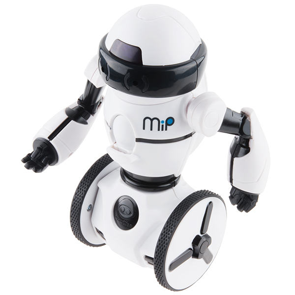
The MiP Robotic Platform is the first self-balancing robot that you get to control and with which you can play games. The MiP can drive, dance, plays games, battle with other MiPs, respond to simple hand motions and can be remotely controlled by a compatible iOS or Android device. But did you know you can hack it?
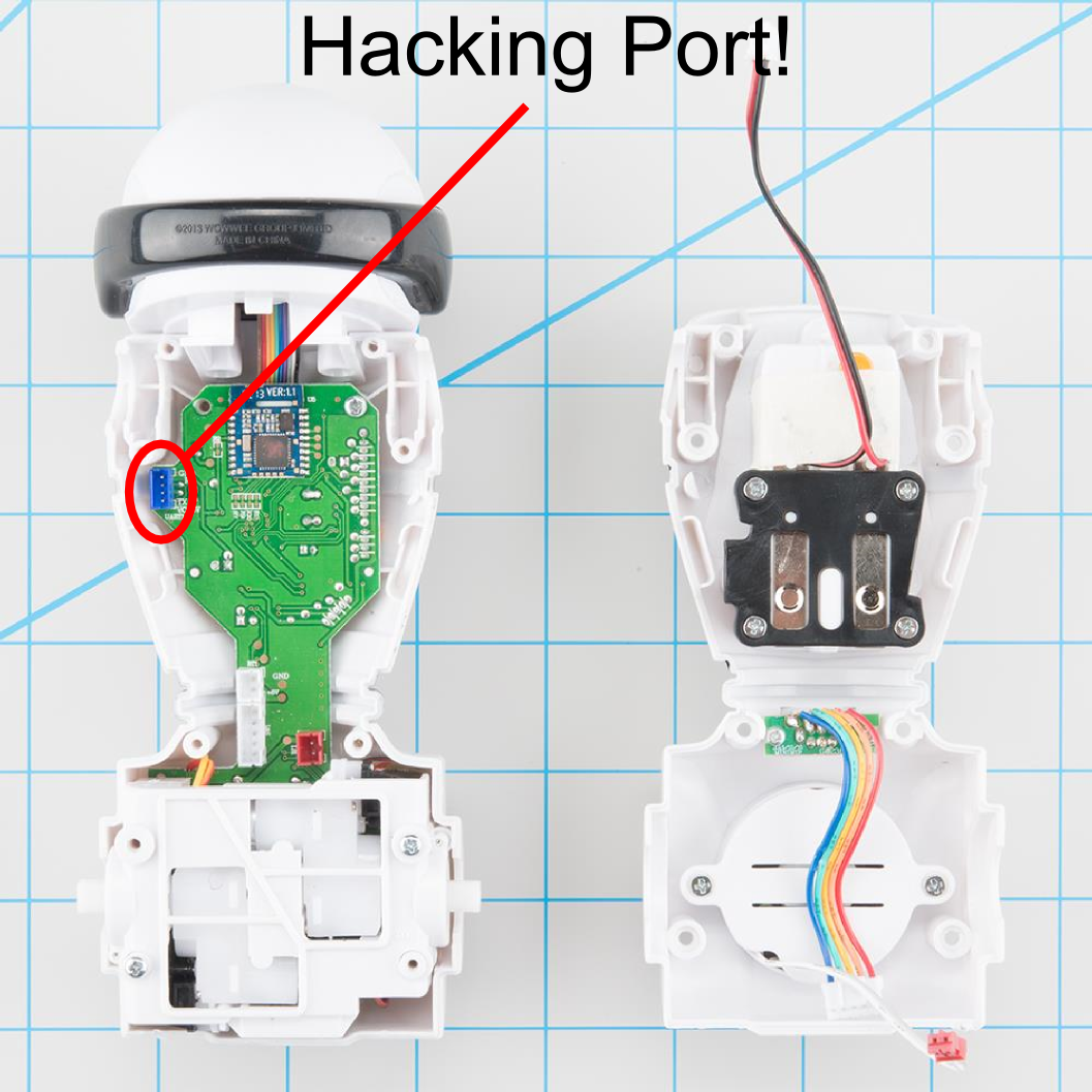
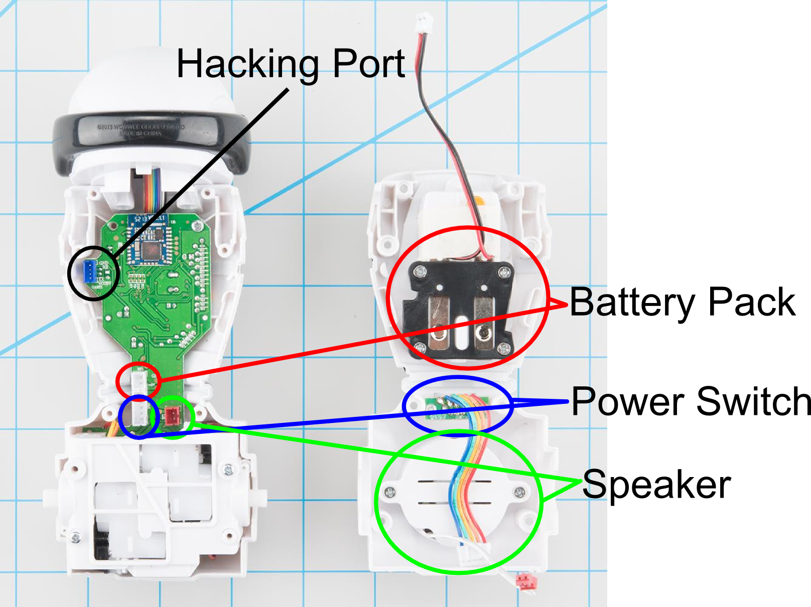
The hacking port breaks out the following signals: * GND - A ground connection to the battery on the MiP * RX - A 3.3v signal level UART receive pin * TX - A 3.3v signal level UART transmit pin * 6v (Battery) - Raw battery power
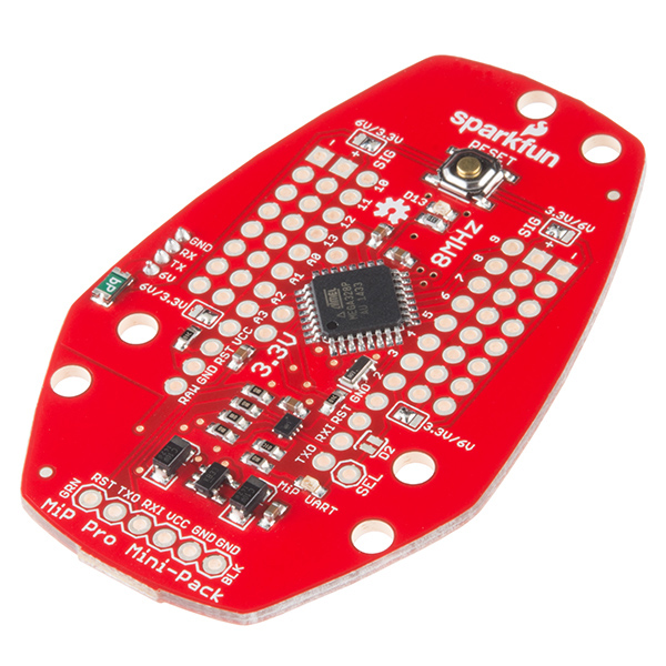
Let's add a Pro-Mini to the mix now! With this you can access the hacking port to add functionality to your MiP.
Required Materials
There are a few components that you will need in order to exploit that port.
Once you have all the parts you need, let's get started!
Attaching the ProMini Pack
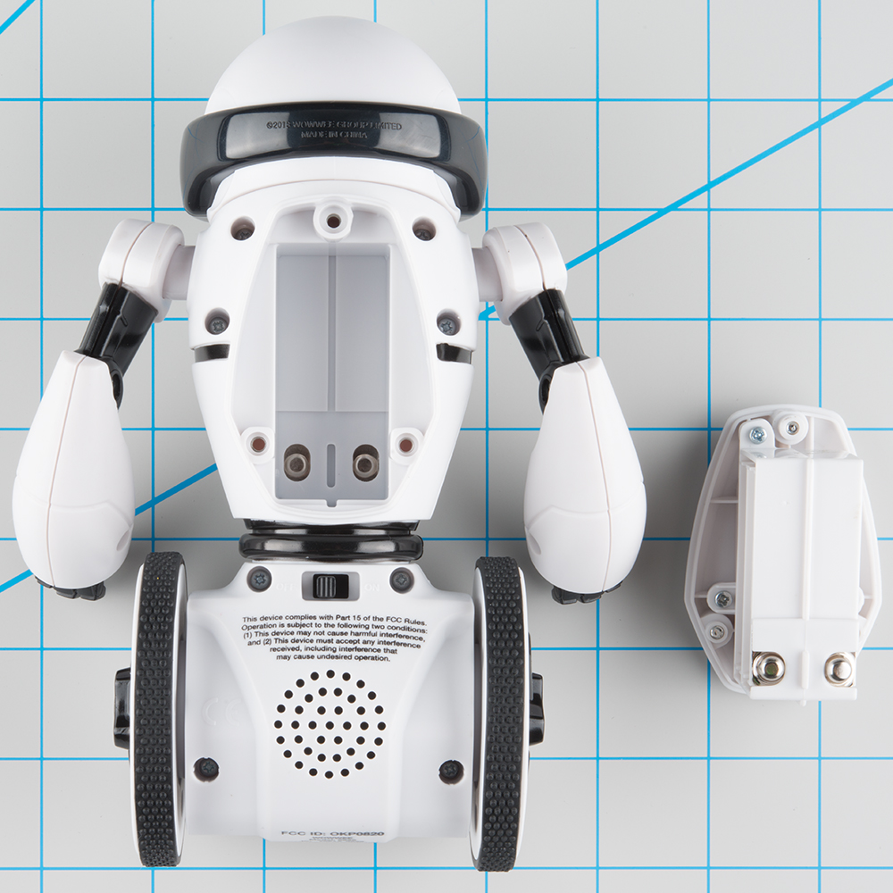
Step 1. Remove Battery Pack
You want to make sure the MiP is powered off and the batteries are removed before we start hacking away.
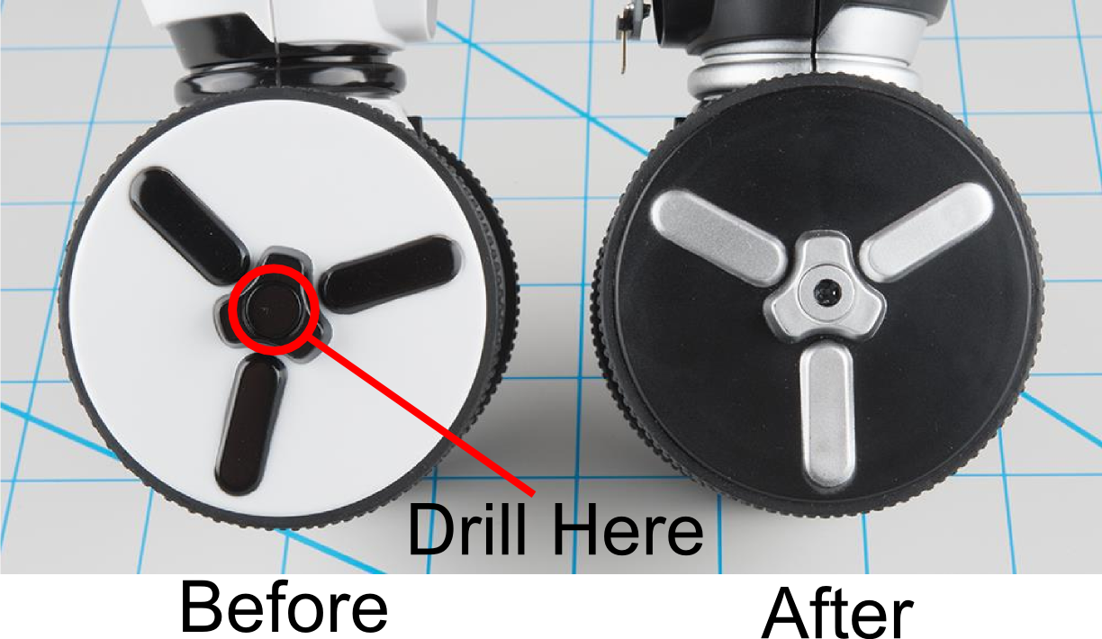
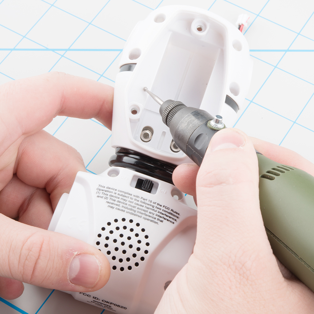
Step 2. Drill and Remove Wheel Screws
Fortunately/unfortunately the manufacturer glued the screw caps on the wheels. Good for consumers, ad for hacking. Take your favorite drilling device, and carefully create a hole in the wheel. This will expose enough of the screw head to get a phillips head screw driver to the screw head. I found that a 3/16" drill bit works great. I have also used a Dremel rotary tool to grind out the plug. NOTE: Remember to drill both sides.
Step 3. Remove Wheels
Using a small phillips screwdriver, remove both wheels. If the holes you drilled were small enough, the screws will stay in the wheels.
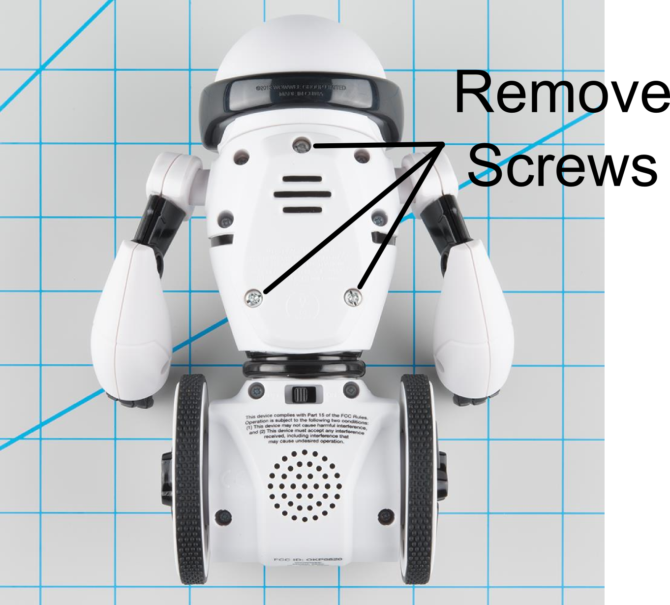
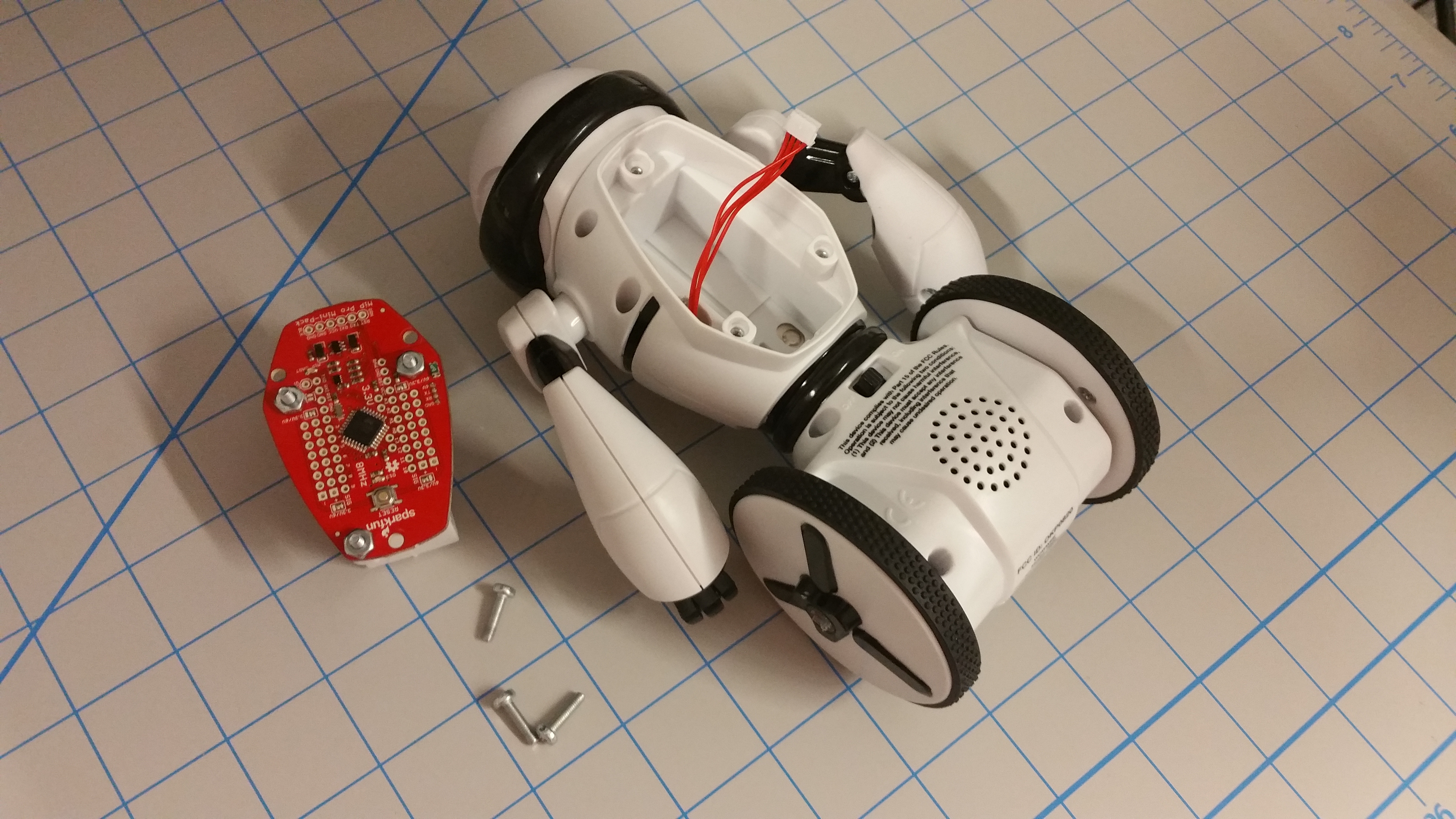
Step 4. Remove the Eight (8) Body Screws.
Remove the 8 body screws that hold the two halves of the MiP together (be sure not to lose the screws so you can put it back together). NOTE: The wheels should already be removed, disregard them in this photo.

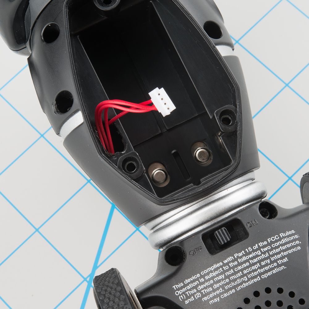
Step 5. Remove Electrical Connections
There are three cables to remove. They are all different enough that it shoudl be obvious where each is replaced. Here is a quick overview of what each cable is for.
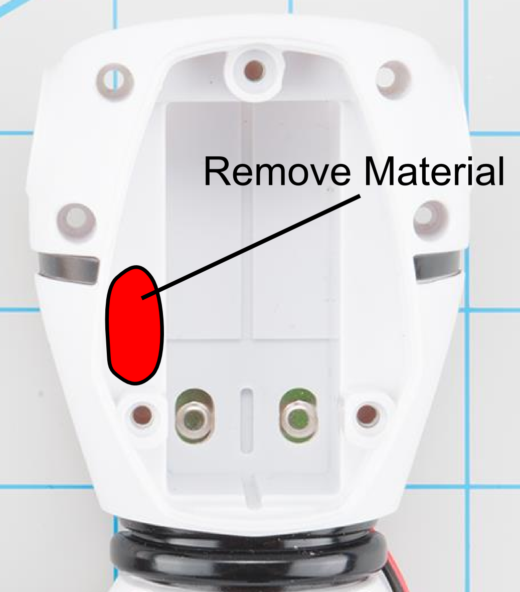
Step 6. Make a hole for the hacking cable
Here is where you will need a rotary tool or some skill with a drill. You need to create a hole in the back to allow the hacking cable to pass through the shell. This doesn't have to look pretty, it will be covered up later.
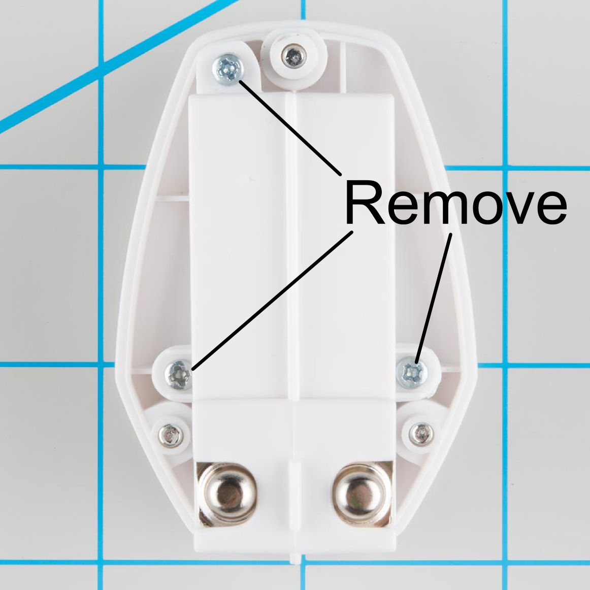
Step 7. Remove the Battery Pack Plate
Remove the three screws that hold the back plate on. It's not necessary to keep these screws.
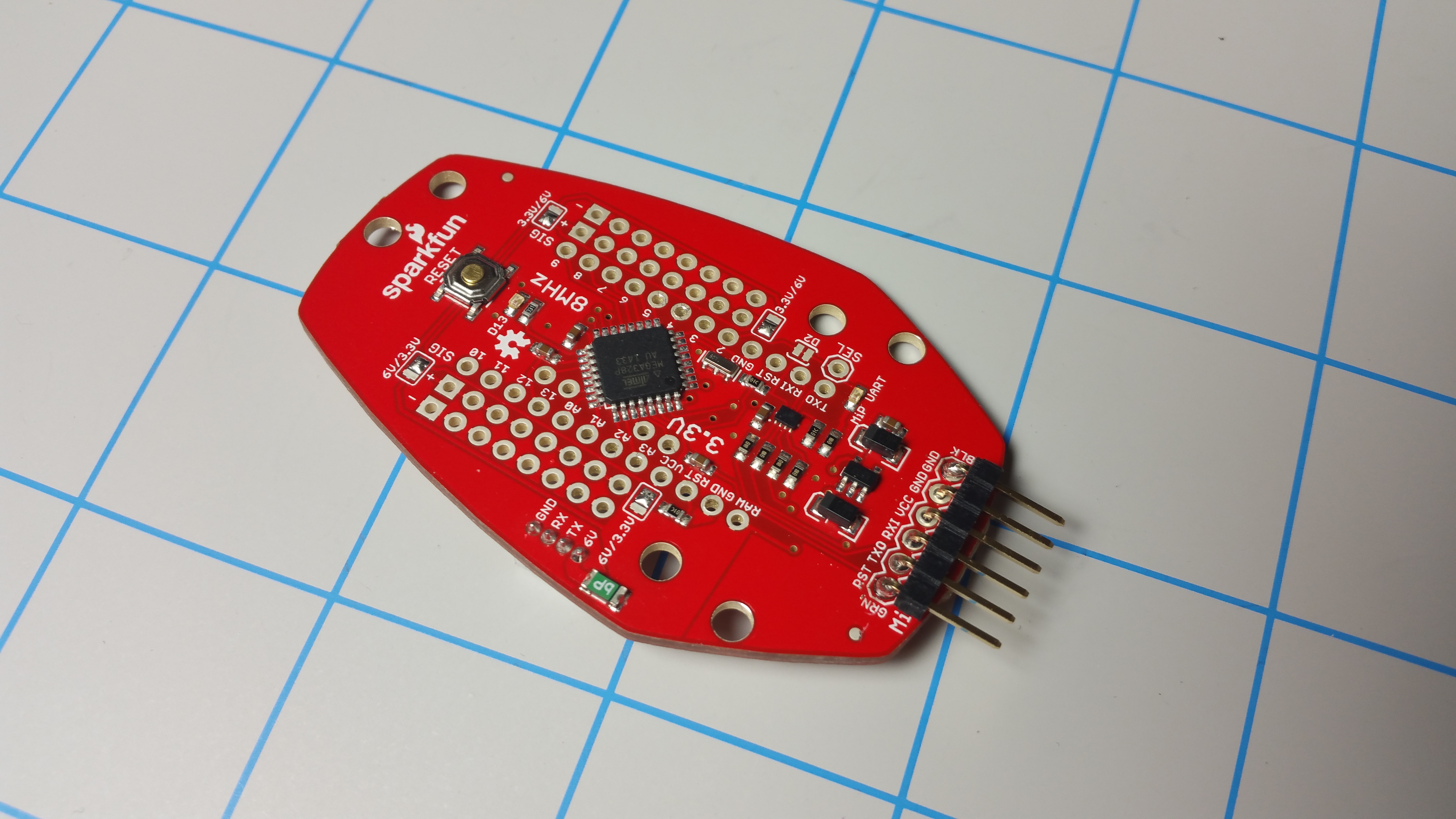
Step 8. Solder header to ProMini Pack
Adding a right angle header will make it simple to program the ProMini Pack.
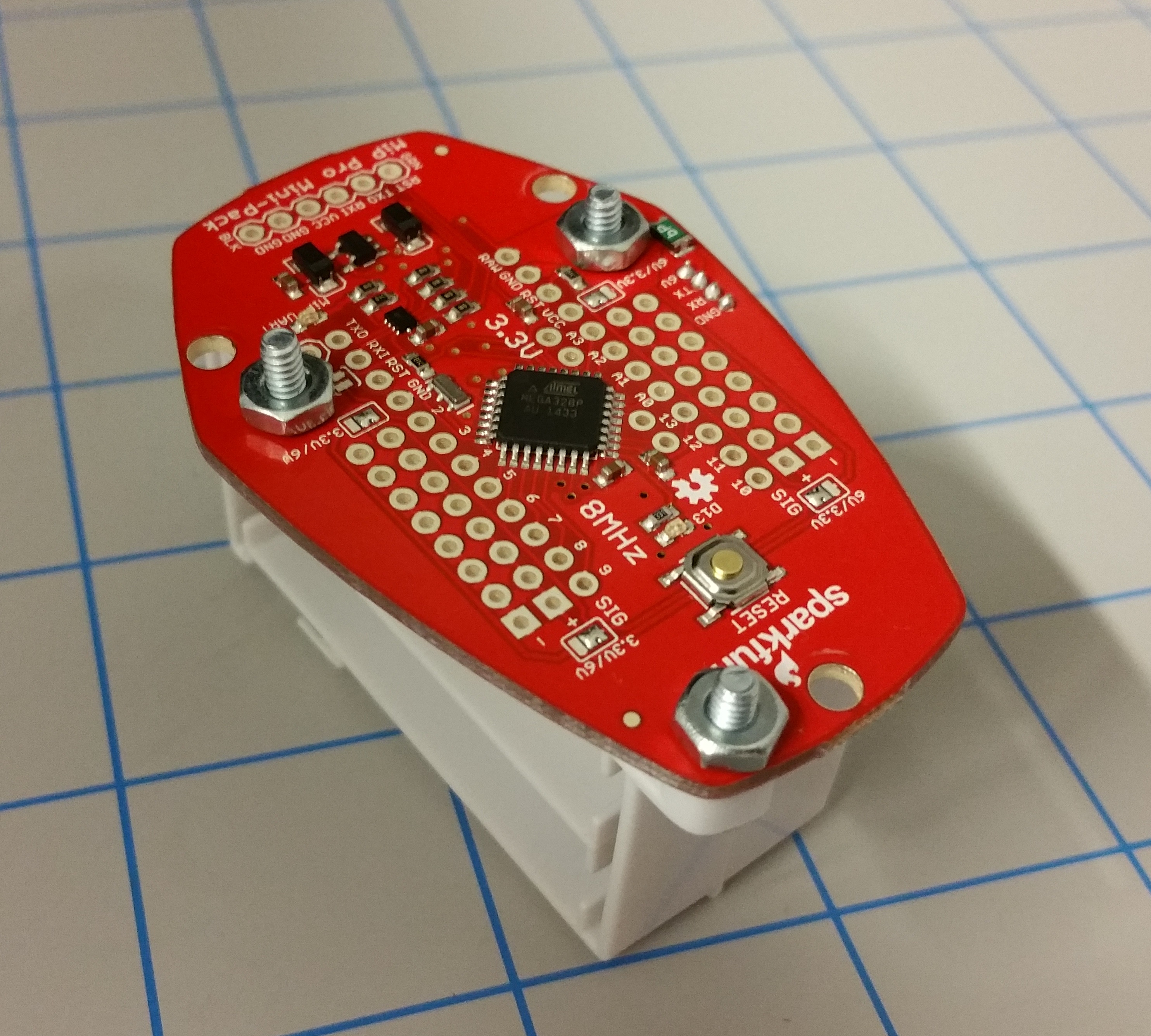
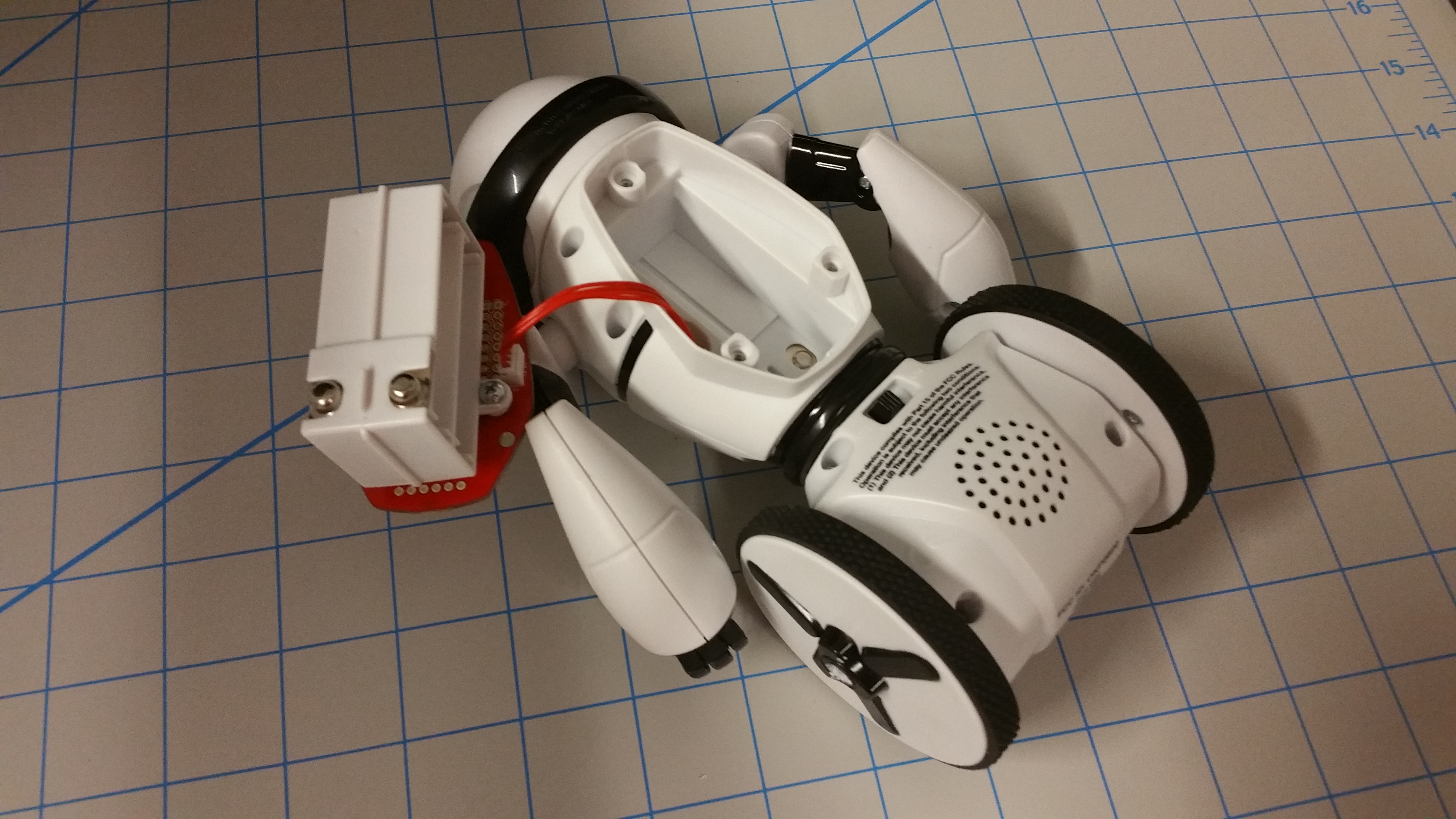
Step 9. Assembling the Battery Holder
Using the 4-40 screws and nuts, re-assemble the Battery Holder by replacing the back plate with the Proto-Pack. Make sure the 4-pin connector is facing towards the Battery socket.
Step 10. Re-assemble the MiP
Before re-placing the back shell, plug in the Expansion Cable. Thread the Expansion Cable through the hole you created in Step 5. Replace the 8 screws that were removed in Step 4. Replace the two wheels.
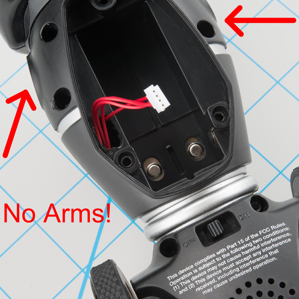
Step 11. Did you forget the Arms?
I managed to re-assemble my MiP with out arms... It happens.

Step 12. Final Assembly
First make sure the Expansion Cable is exposed. Then plug this into the assembled battery holder. Once the connection is made, simply replace the battery holder and use the three M3 x 12mm screws to complete assembly. NOTE: Don't forget to install the 4xAAA batteries
Step 13. You're Done!
Admire your fine craftsmanship and start hacking!

Installing the Library and Using commands
The MiP has a very complex set of commands that can be used. To get started, first download the Arduino library and install it into your Arduino IDE. Take a look at this tutorial on installing Arduino Libraries.
To find a complete list of commands and functions head over to the Github page where we will continue to add functionality as it becomes available.
The Demo Sketch is very simple to show how the basic library works:
language:c
#include "MiP_commands.h"

MiP MyMiP(2);

void setup(){

  MyMiP.init(); //Serial port is configured for 115200
  Serial.print("MiP is Alive!!!");
  delay(100); //Need a delay to let the buffer clear before sending new commands

}

void loop() {

MyMiP.playSingleSound(BURP);  //Make burp sound
delay(100);
MyMiP.distanceDrive(20, 45);  //Drive +20 cm and turn 45 degrees
loop_LEDs();  //built function to blink LED's

delay(5000);

}

void loop_LEDs(){

    MyMiP.setChestLED(255, 0, 0); //Set LED to RED
    delay(200);
    MyMiP.setChestLED(0, 255, 0); //Set LED to GREEN
    delay(200);
    MyMiP.setChestLED(0, 0, 255); //Set LED to BLUE
    delay(200);

}
Resources and Going Further
Now that you are up and running with your MiP ProMini Pack. Here are some other tutorials you may be interested in looking at: