Gas Pump Skimmers
 Nate
Nate Introduction
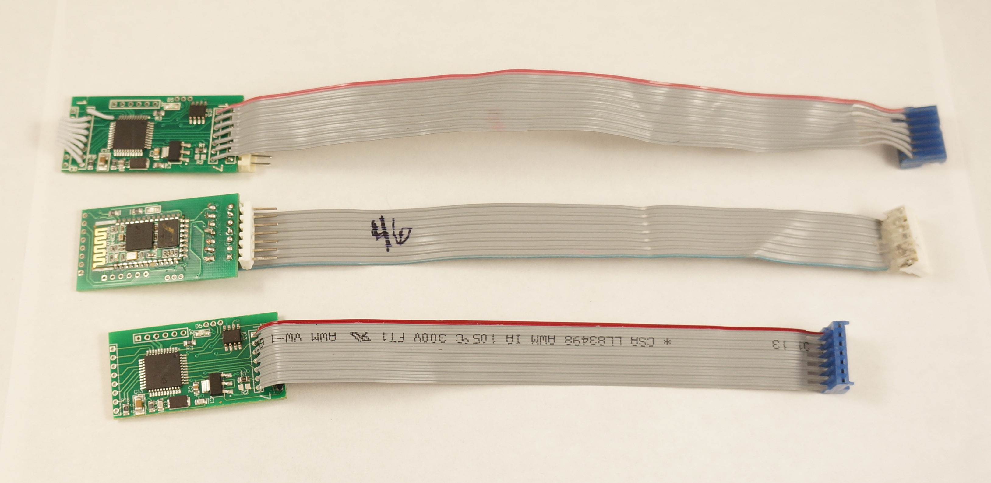
What’s the first thing that should scare you? There’s three. And the next? The label ‘46’. They’ve got so many in the field criminals need to number them just to keep track.
This is the not the first or the second time SparkFun has dealt with credit card skimmers. The difference is that this time the local governmental agency politely asked for help and we’re always down for trying to put a stop to bad actors.
We were given three skimmers found installed within gas pumps with the request that we try to get the data off the board so that the agents could let those who’ve had their credit card compromised know so they can get a new card. Not great, but it’s a start. Second task: can we build a jig or system so that they can more easily poke at these systems in the future? We were able to accomplish both as well as build an app that detects known skimmer in the area.
Now, for those who don't want to read through the gritty details here's the summary of how the SparkX 'Skimmer Scanner' app works [1]:
These skimmers are cheap and are becoming more common and more of a nuisance across North America.
The skimmer broadcasts over Bluetooth as HC-05 with a password of 1234. If you happen to be at a gas pump and happen to scan for Bluetooth devices and happen to see an HC-05 listed as an available connection then you probably don't want to use that pump.
The Bluetooth module used on these skimmers is extremely common and used on all sorts of legitimate products and educational kits. If you detect one in the field you can confirm that it is a skimmer (and not some other device) by sending the character 'P' to the module over a terminal. If you get a 'M' in response then you have likely found a skimmer and you should contact your local authorities.
How the Skimmer Scanner App Works
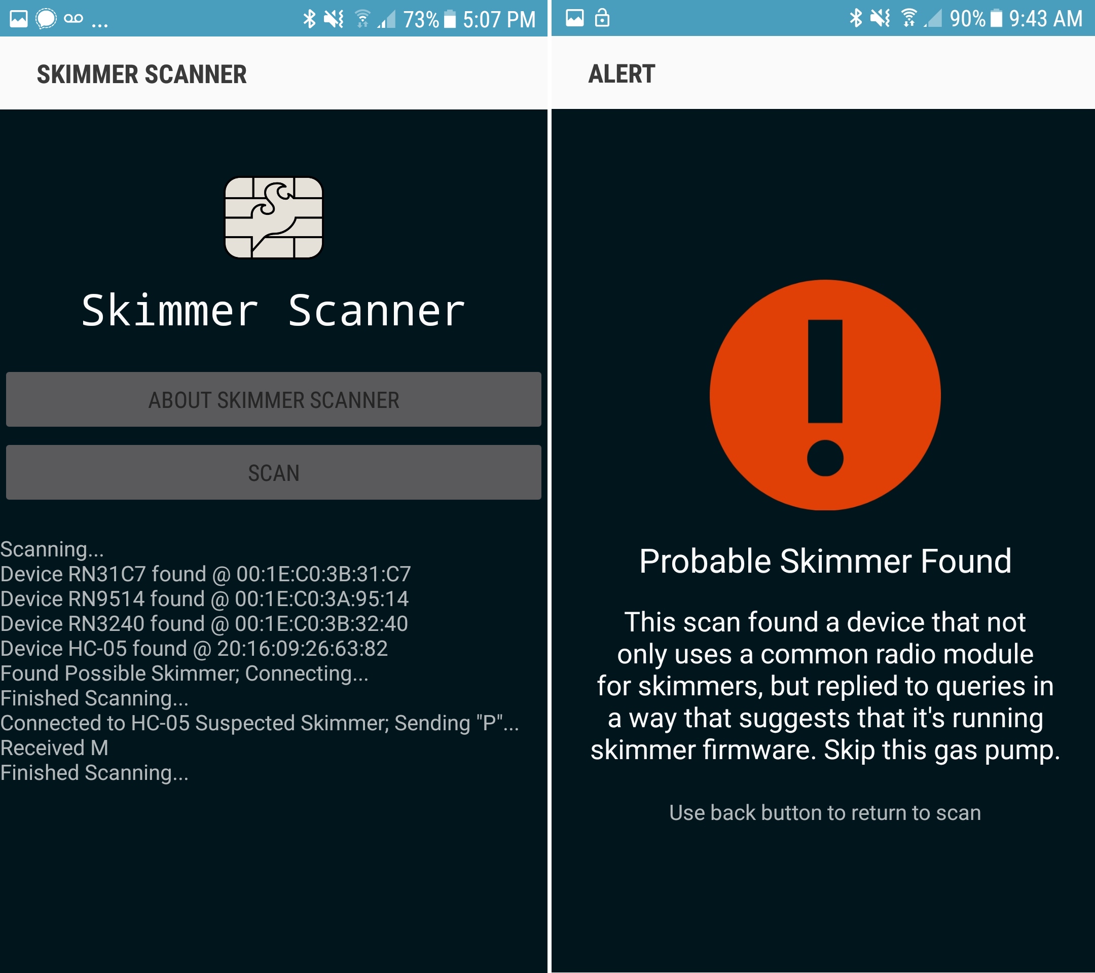
The Skimmer Scanner is a free, open source app that detects common Bluetooth based credit card skimmers predominantly found in gas pumps. The app scans for available Bluetooth connections looking for a device with title HC-05. If found, the app will attempt to connect using the default password of 1234. Once connected, the letter 'P' will be sent. If a response of 'M' then there is a very high likelihood there is a skimmer in the Bluetooth range of your phone (5 to 15 feet).
Skimmer Scanner is free, open source, and was available for Android [1]. The app does not obtain or download data from a given skimmer nor does it report any information to local authorities.
If you detect one in the field let us know! We'd love to hear about it.
Do Something About It
These skimmers are most scary because there is no one being held responsible or tasked with prevention. If your credit card number is stolen you simply contact the provider and they will (usually) refund any fraudulent charges and send you a new card. In turn, the credit card companies simply do a charge back to the merchant where the fraudulent charges took place (taking the money from the merchant and refunding it to the customer whose card has been stolen). Gas stations rarely have alarms or indicators on the pumps so it's unclear if they ever know the pumps have been opened. And the fuel pump manufacturers have no incentive to install digital or audible alarms on the pumps. (That costs money.)
Reader Anthony David Adams informed us who really gets charged in these situations. You can read his response here.
Are you angry that your card has been stolen, again? Contact your local congress person or senator and ask them to pass legislation that fines gas stations $100 for every card that is discovered on a skimmer in one of their pumps. It's ultimately up to the gas stations and pump manufacturers to secure their pumps.
How a Gas Pump Skimmer Works
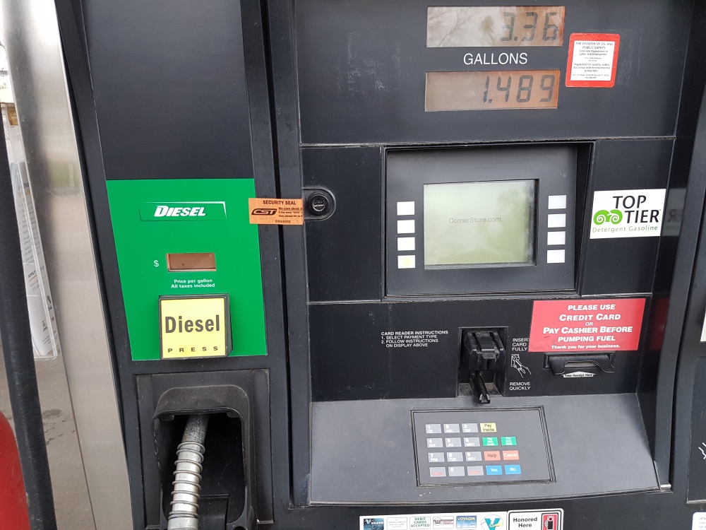
Essentially, the perpetrator opens a pump using one of a few master keys, unplugs the credit card reader from the main pump controller, plugs the card reader into the skimmer and plugs the skimmer back into the pump controller. This reportedly takes less than 30 seconds.
A skimmer is basically a man in the middle attack. The skimmer listens for all the serial traffic from the credit card reader (clear text at 9600bps) records it to an external piece of memory (flash in this case) and then passes that same serial traffic onto the pump controller. When you use one of these modified pumps the pump controller charges your card and you’re none the wiser, but your credit card details are stored in memory.

Hours or days later, the perpetrator returns to the gas station and connects over Bluetooth to the compromised pump. Once connected the skimmer sends the contents of the EEPROM (all the recent credit card numbers) over the air to the perpetrators cell phone or laptop where it’s logged.
Skimmer Design
Let’s dig into how these skimmers are designed...
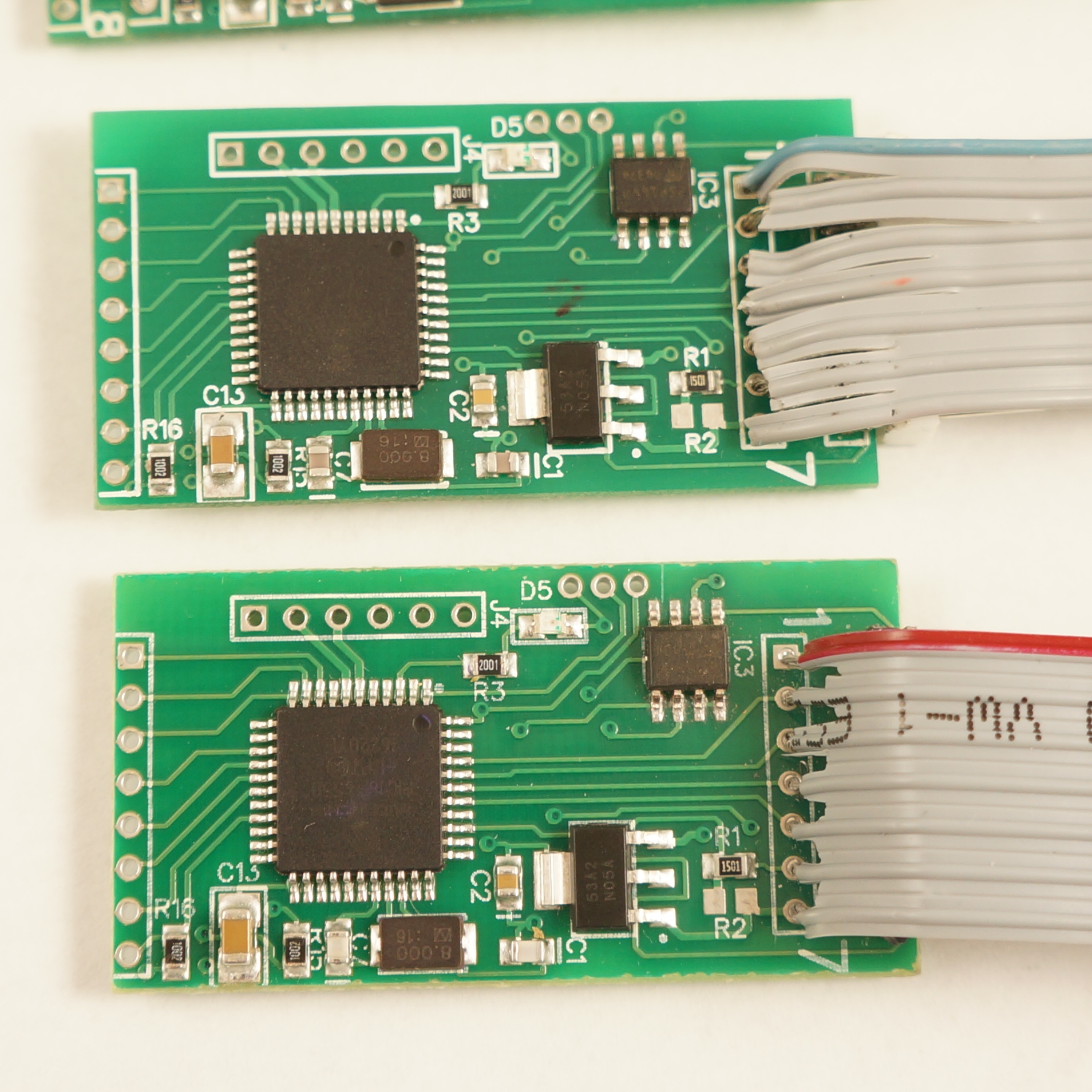
This type of skimmer seems to be very common. A quick image search shows this model all over North America.
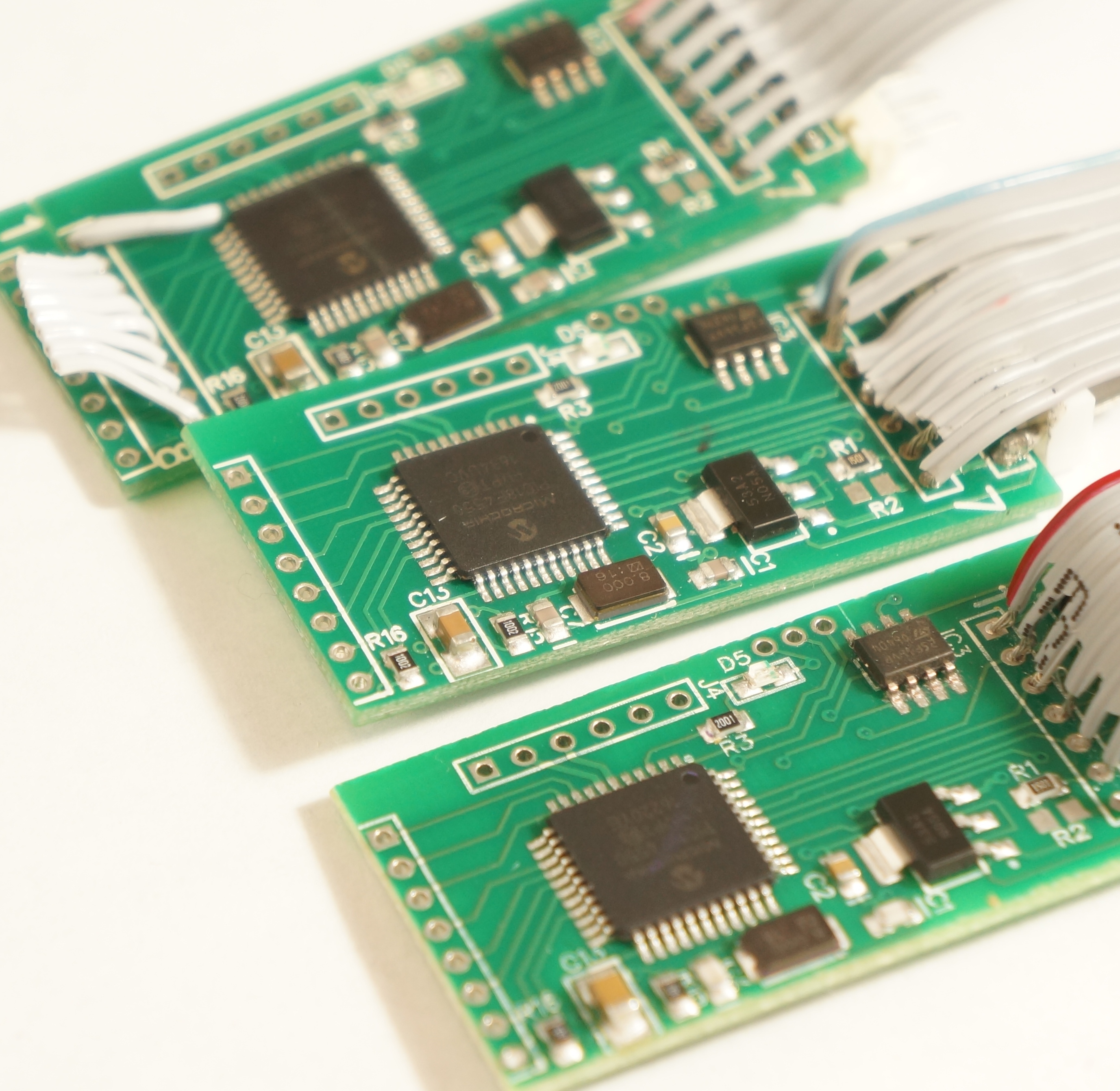
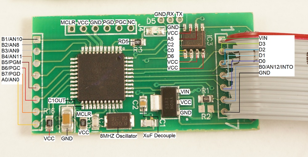
The setup is very straight forward, but has some odd design choices. The PIC18F4550 microcontroller communicates with the Bluetooth module over serial, and also talks to an SPI Flash. Signals (serial characters) from the credit card reader are recorded by the PIC to the SPI EEPROM. When a cell phone or tablet connects to the Bluetooth module a serial connection (called Serial Port Profile or SPP) is created. Whatever serial characters the cell phone sends are sent to the PIC. For example when the character ‘?’ is sent from our Bluetooth enabled tablet to the Skimmer, the Skimmer responds with the character '1'.
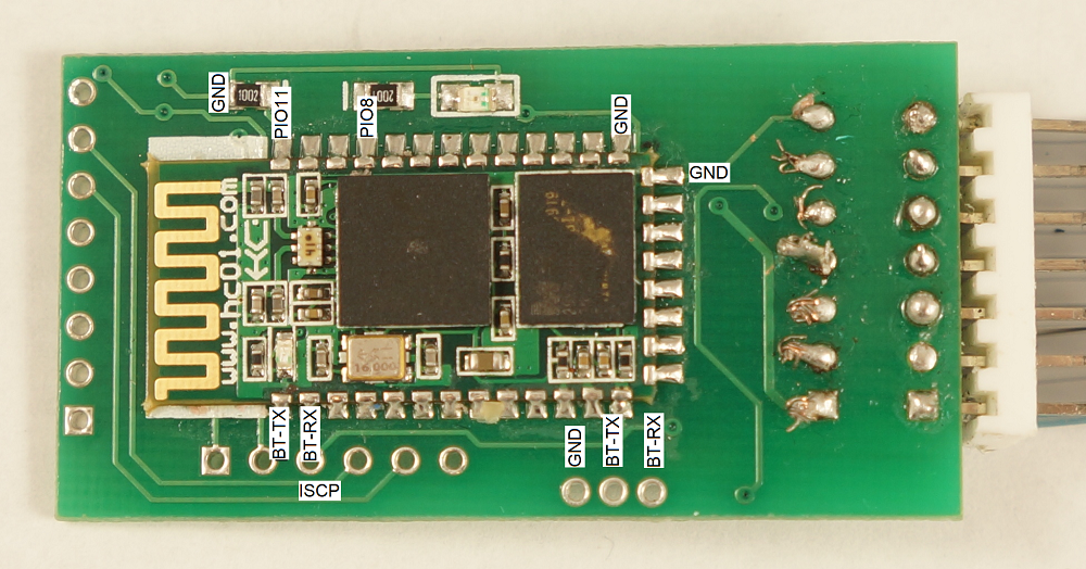
Front of the Skimmer
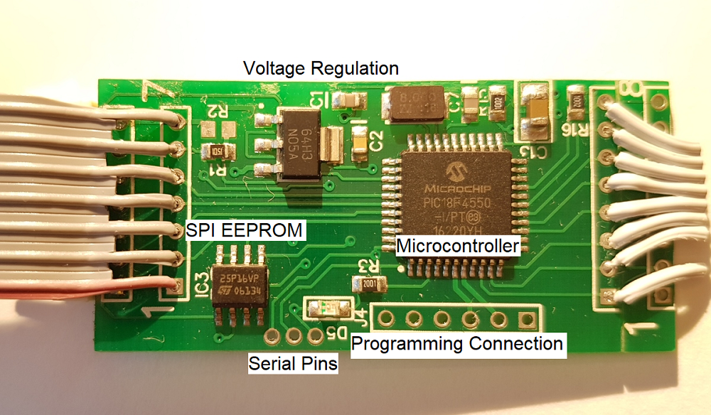
The front of the board is composed of a PIC18F4550 microcontroller, an M2P16 SPI EEPROM with 16Mbit flash memory, and a standard LM1117 3.3V regulator.
To get into some gritty details:
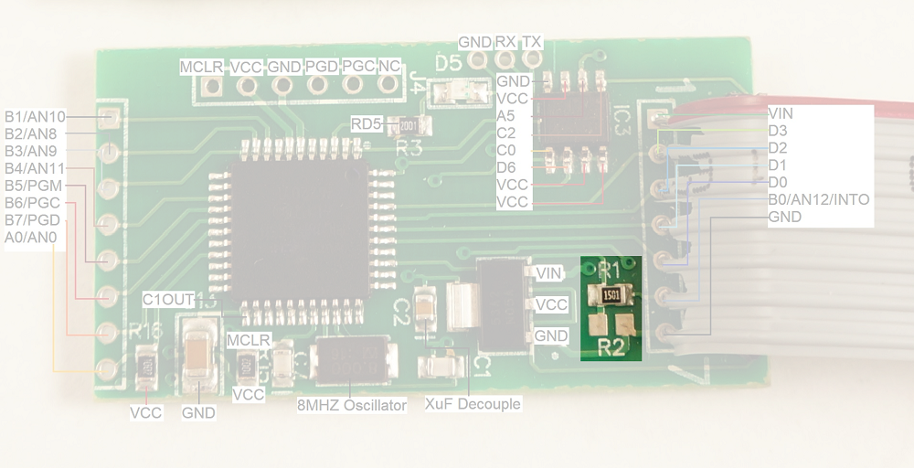
- R1 and R2 look to be a voltage divider when needed (R2 is not populated) to drop the voltage of the signals coming from the credit card reader. I presume the reader is outputting 12V signals and R1 (1.5K) is there to limit the current into the receiving pin, thus protecting the PIC from damage.
- There are three serial pins shown at the top of the picture. From left to right: GND, RX, TX. These seem to be an easy serial connection to the PIC. Perhaps used for bootloading new firmware. These pins connect to the Bluetooth module's RX and TX pins (respectively) and make it very easy to hook up a logic analyzer to sniff the serial traffic. (Thanks skimmer designer!)
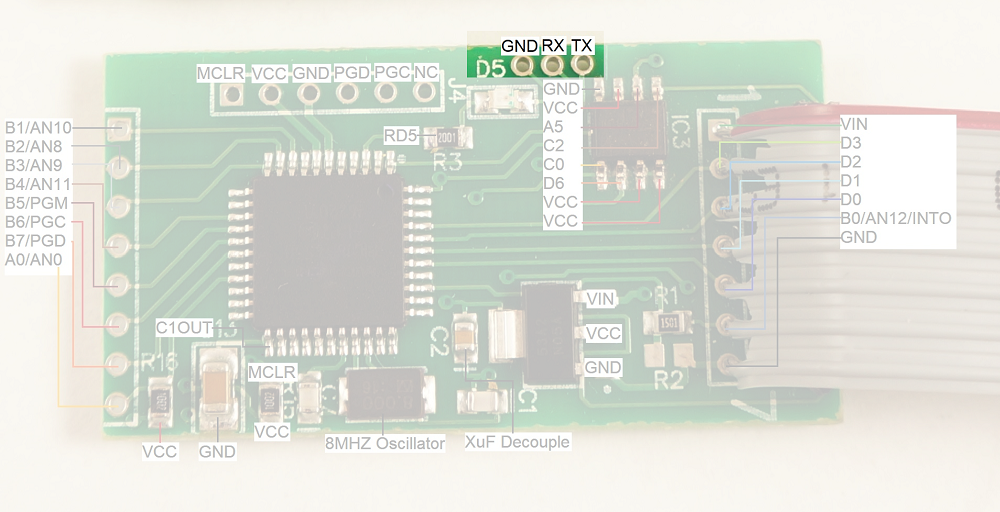
The voltage regulator is very common with a large package to (probably) withstand getting hot when given various input voltages (regulating 12V down to 3.3V can produce a bit of heat)
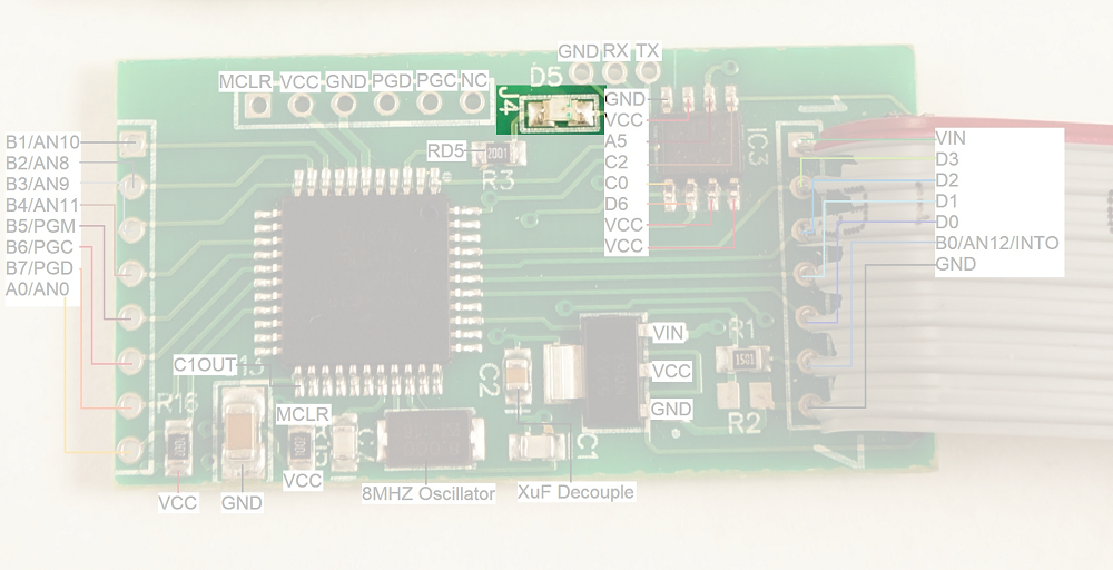
D5 is a status LED.
J4 is the super common PIC ICSP (in circuit serial programming) header. It's used to get firmware onto the PIC18F4550.
- C1 and C7 are loading caps to the 8MHz crystal. This makes sense as most PIC18F series can't run above 10MHz at 3.3V.
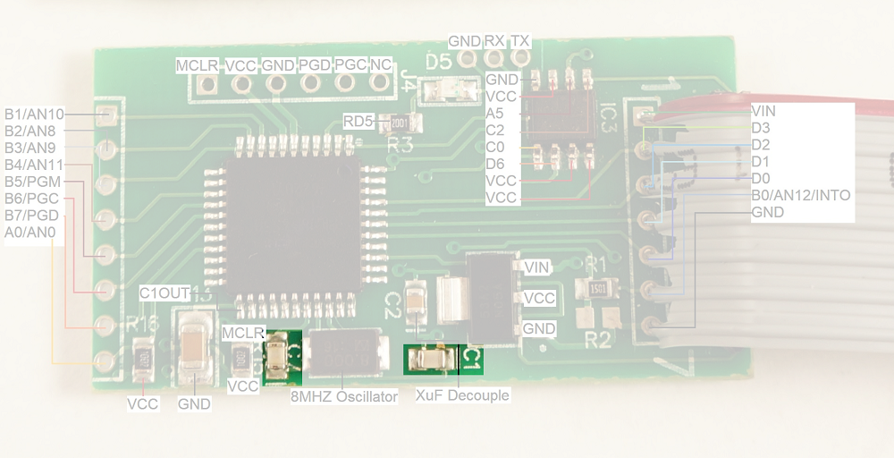
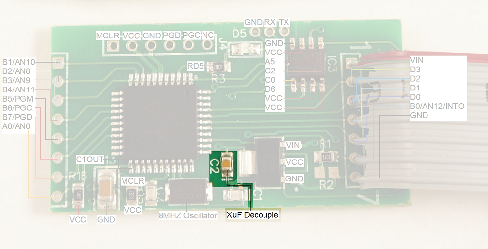
- C2 looks like a 0.1uF decoupling capacitor.
- R15 is a 10k pull-up on the reset (MCLR) line
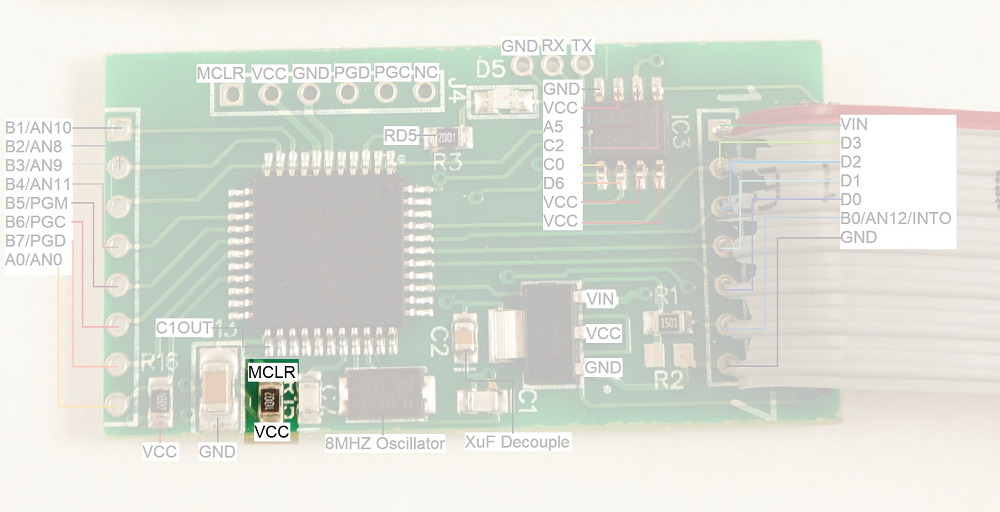
- C13 is a large cap on RA4/T0CKI/C1OUT/RCV. This could be a digital I/O, Timer0 external clock input, Comparator 1 output, or external USB transceiver RCV input. None of these have a clear reason to be connected to a large decoupling cap. This pin is not connected to any other part of the circuit.
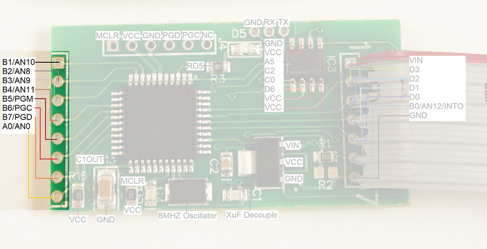
The main connection to the credit card reader is via the connection labeled '1' through '7' shown on the right with a gray cable installed.
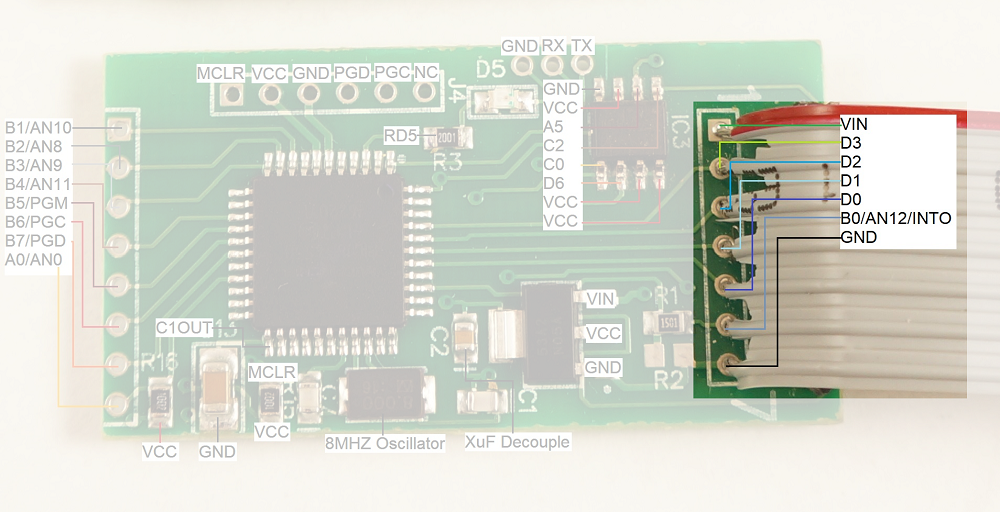
It is unclear what the second connector (shown on the left in the image above) is used for. This connection could be used for a variety of different things as the pins on the PIC that are broken out could be used as either inputs or outputs. My guess is that this is the connection to the keypad so that the skimmer can record pin numbers (for debit cards) when the pump has the right model or compatible keypad.
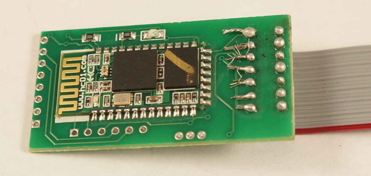
Rear of the Skimmer
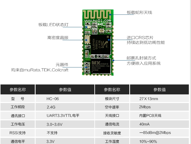
These modules use an extremely common Bluetooth module called the HC-06. These are roughly $3 per unit and perhaps cheaper in quantity. Bluetooth has gotten shockingly cheap!
More on the Bluetooth module is below.
Build Quality
Interestingly, between the three units we were given we found three grades of assembly: excellent, good, and trash.
The main PCB assembly of the three units looks of reasonable to high quality. The front side of the skimmer (containing the PIC microcontroller) has been assembled with standard SMD practices using a solder paste, stencil, and reflow. It looks like it was mass produced from the quality of the fillets.
The Bluetooth module and various components on the back side look hand soldered but done by someone who knows how to use flux and how to solder well. The Bluetooth modules were most likely hand soldered to reduce the overall manufacturing costs (it basically costs double to stencil and reflow a 2nd side).
The cables and connectors were added by someone else, most likely the perpetrator. It’s really bad. On two units the stripping of the wire and solder is so poor that units will probably fail in the field because of shorting between pins.
Two units have a 7 pin polarized connector with the tab cut off, possibly because they don’t know which way the pump controller will plug on. This is either very amateur (they guess when they plug in their unit which is pretty cavalier because it could fry their unit, the credit card reader, or both) or they’ve found that the connectors inside different pumps have different (opposite) orientations and they want to build a unit that can quickly work with either polarization. It’s unlikely the pump controller market would gravitate towards the same number of pins using the same type of connector but use two different orientations. So I’m guessing the builder of these units is not knowledgeable enough to figure out where pin 1 lives on the polarized connector and just resorts to guess and check: Plug it in, does it work? No? Switch it around the other way.
Components
Let's look a bit closer at each of the main components.
Microcontroller
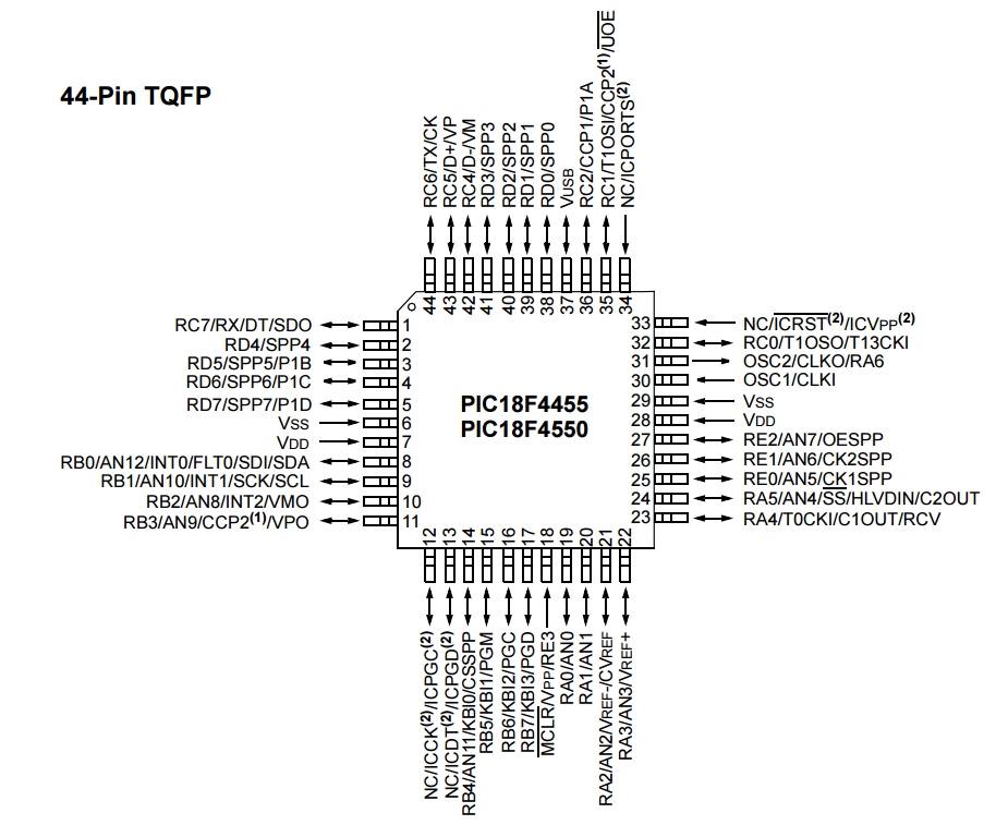
The brain is a PIC18F4550 running at 8MHz and 3.3V. The 3.3V regulator has a single decoupling cap. A very basic configuration and could probably handle larger voltages like 12V without getting too hot.
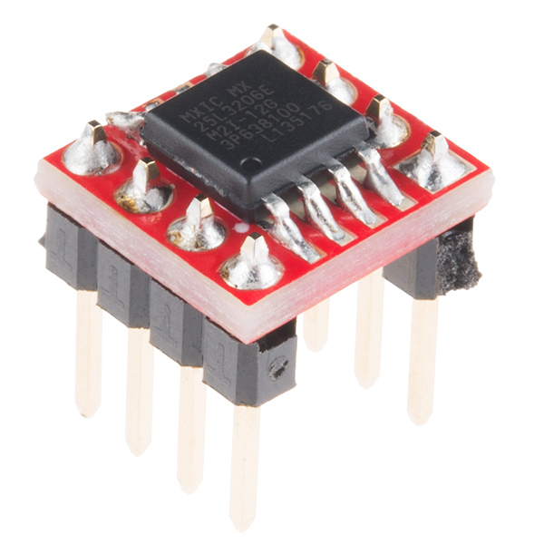
EEPROM

The IC labeled 25P16VP seems to be a NOR flash memory from ST/Micron with a full part# M25P16. Curiously, this part is being End-Of-Lifed (EOL). EOL notice is here dated December of 2016 with last shipment dates into 2021. Perhaps they are using this part because it is super common and/or super cheap. The EEPROM VCC is 3.3V which follows why the board runs at 3.3V (along with the 3.3V Bluetooth module).
Bluetooth
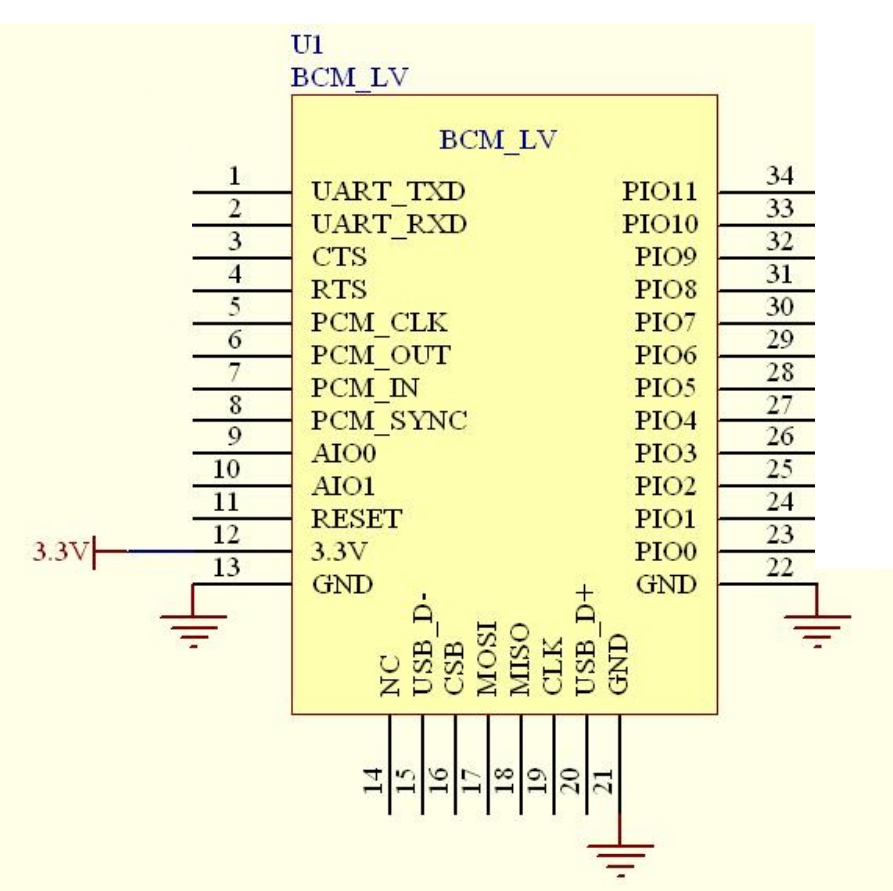
Above is the recommended wiring of the module showing various pin connections. Toning out the connections to the module, everything is pretty standard and expected. PIO11 on the skimmer is curiously tied to GND with a 10K. There is an LED on PIO8. Here is a good breakdown of all the various Bluetooth module revisions from the HC-01 company.
Querying the module over the air we found the Bluetooth module has all the default settings in place. The designers of the skimmer never took the time to modify the settings:
- Baud rate = 9600
- Connection Password = 1234
- nl/cr line endings not required
- AT commands are required to be in uppercase
- Firmware version = hc01.comV2.0
- Name = HC-06
- No parity
- SLAVE mode
Did you get that? All three devices we found have the defaults in place. This means a few things:
- The module broadcasts its ID as HC-06 so we can detect them easily
- The password is 1234 so we can connect to them easily
Astute readers see where we are headed...
Initially this blew my mind. If I were to design a bluetooth skimmer I would program the module to NOT broadcast its ID, I would change the ID to something only I knew, and I would change the password from 1234 (headsmack). I would then create an app that knew the IDs of my various bluetooth IDs and connect to them privately (without publicly broadcasting their IDs). But then a few things struck me:
- These devices are cheap. The BOM (bill of materials) is less than $4. That puts an estimated retail price of this device at $10.
- While the SMD build quality is professional, the soldering of the ribbon (the gray cable that connects to the credit card reader) is horrendously bad indicating the perpetrator has very little experience with soldering and probably zero experience with electronics.
Years ago it took someone with knowledge and skills to build a credit card skimmer. Now criminals are buying these off the shelf with very little knowledge and slapping them together. It's basic user design theory: when your customer is not so smart make it idiot proof so they don't contact you for support. The designers of this skimmer were smart, it's better to make these devices easy to connect to than to add a layer of security. What's the worst that could happen? The device is detected and removed from the pump. Meanwhile, 10 more have been deployed for a total cost of $100.
Characteristics of the Device
We powered the skimmer with 5V from USB. On powerup the main status LED blinks 3 times. The Bluetooth LED blinks fast at 4Hz when powered but not connected.
Connecting to the skimmer using Bluetooth on a computer is straightforward. We used the default password of 1234 and noticed the Bluetooth LED blinks on at 2Hz and then off for 2 seconds when connected.
On our setup COM-6 was the bluetooth SPP that became available once we were connected. Sending ? to the skimmer caused it to respond with 1 at 9600bps.
Known Commands
Here’s what we were able to glean from hammering the skimmer with various serial strings.
- Power the skimmer with 5V to 12V from the gray cable (or 3.3V into VCC)
- Connect to HC-06 with password 1234 using a laptop
- Open a terminal program at 9600bps
- ‘?’ is a good way to see if module is responding. (Numbers don’t do anything on their own.)
- Lower case letters do nothing
Identified Commands:
- ? - returns 1
- P - returns M
- D - Waits for 6 characters then stores them. Originally ‘123456’ and we thought it was the device ID or password. However, changing this setting does not seem to have an effect.
- C - Displays the 6 characters that are stored based on D
- @ - Look up memory location. Follow the @ with two more characters in binary form, returns credit card details stored in memory. For example, @[00][01] (shift+2, Ctrl+shift+2, Ctrl+a) returns the 2nd byte stored in EEPROM. See ascii table for info on how to send binary characters from keyboard combinations.
- % - waits for a character then does nothing
- E - causes serial to stop responding to serial commands. BT still open/connected. Power cycle device to get it back responding. This could possibly be used to deactivate a device in the field.
- ~ - Erase all SPI flash. This is how to erase all the credit card numbers. Unit blinks the status LED for ~20 seconds (EEPROM takes time to erase). The unit will buffer any incoming serial characters during the time it takes to erase the EEPROM (serial interrupts and buffer are being used).
A skimmed credit card record looks like this (we've altered the card number):
T1 %B374328830305879^YOU/A GIFT FOR            ^20042221330999242?
T2 ;374328830305879=200912211090924100000?
This looks like a direct copy of the serial we would expect out of a serial card reader. T1 indicates track 1 data, T2 for track 2, etc. The records are stored on EEPROM in clear text (remember, make it idiot proof for the user). It looks like someone used a gift card to buy gas. Note that this record is 113 characters. Let's say a record is 256 bytes. With 16Mbit of flash storage that's 2MB or approximately 7,800 credit card records that could be stored on a device. (Yikes.)
On the units we were given we found on average 24 records per device. This seems low. I'm not sure where these devices were located but one would expect at least 24 credit card users per day. This may indicate the perpetrator was regularly visiting the pumps and harvesting the records on a daily basis.
Getting Data Off Skimmer
We are not going to provide an example app that pulls data from the device. If you're savvy enough to build an app from the information provided in this tutorial you are likely to earn more money using your mad skills for good rather than evil.
If you're a law enforcement official you should have physical access to the device. There are a few methods to get the data from the EEPROM.
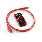
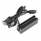
First, you'll need an EEPROM reader. We like using a cheap SPI programmer from Amazon. The software for Windows is a bit hard to locate. We had the best luck with version 1.29 from Tosiek Zanakow’s website. We have hosted a copy of the software here as well. Use at your own risk.
Next you'll need to connect the Programmer to the EEPROM. There are two methods: Using a SOIC clip or hot-air removing the EEPROM. The SOIC clip is the least destructive method but requires dexterity and patience. Hot-air rework is more reliable but requires removing the IC from the board and may create evidence provenance issues.
SOIC Clip Method
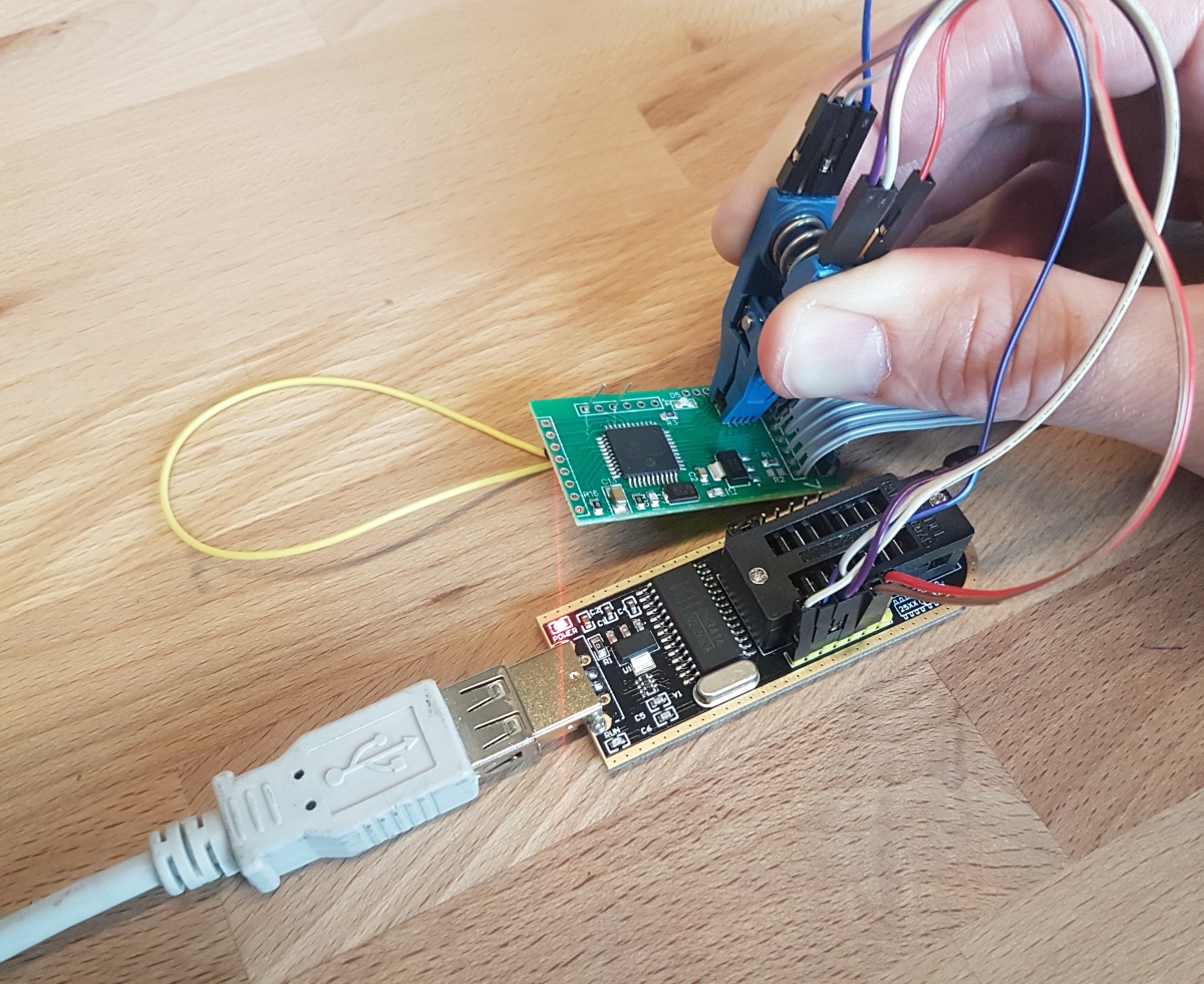
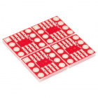
We use a SOIC Test Clip to make a temporary electrical connection to the SPI EEPROM. 12" Female to Female jumper wires connect the SOIC Clip to the EEPROM Reader. The female jumper wires connect nicely with the 6 SPI pins on the CH341A EEPROM Programmer. Only 6 wires are needed; the write protect and hold pins can be left floating. We selected the ES25P16 from within the software to read the IC over SPI.
The last thing you need to do is to put the PIC18F4550 into reset. This is because the CH341A will provide power to the skimmer. Once power is applied the PIC will boot up and attempt to connect with the EEPROM. If you're trying to read the EEPROM through the clip at the same time you'll have bus contention. This is bad and will prevent the programmer from correctly reading the EEPROM.
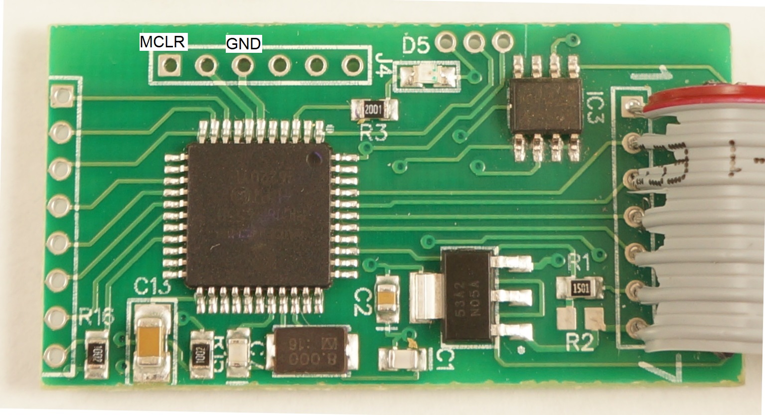
To get the PIC into reset you'll need to either hold or solder a wire from MCLR to GND. This will cause the PIC to stay in reset and allow you to read the EEPROM to a binary file from the CH341A software. Renaming this binary file to a .txt extension will make the information viewable in a normal text editor.
The problem with this method is that the SOIC clip is difficult to keep in place. Things like to move causing the clip to slip off the EEPROM. The connections are not great but with a little practice it can be made to work.
Hot-Air Removal
The alternative method is to use hot-air to remove the EEPROM from the skimmer and then solder it to a SOIC breakout board. Solder male headers to this breakout board and you will be able to make solid connections from the EEPROM to the EEPROM Programmer and read the contents. You will not need to hold the PIC in reset for this method to work (because the PIC is no longer connected to the EEPROM).
Firmware
We were able to pull the firmware from the PIC using a PICKit 3. You can get a copy of the HEX file here. The firmware on all three boards was identical. The firmware is curiously small, occupying 0x0000 to 0x07F0 (about 2,000 bytes). I sneeze Arduino sketches that are bigger than that.
Update: A few readers pointed out the fuse bits have been set to protect and prevent reading of the firmware. Decapsulation and fuse clearing would be the next step but is beyond our capabilities at the moment.
One unknown: Why use a PIC18F4550 at all? It’s more powerful with way more flash than is needed. You could do this with a smaller device like an ATtiny or a cheaper device like an ARM-M0 (SAMD11s are amazing). Perhaps the extra pins are needed for keypad decoding. Perhaps the PIC18F4550 is very low cost wherever these devices are made. Perhaps this device was designed by someone and the design was never re-visited to reduce costs (who cares when the BOM on this skimmer is already less than $5?).
I am not a hacker, I just play one on TV (poorly). If you are able to decompile the HEX code into assembly and can make some sense of the function of the firmware, please do so. We already know enough about the available commands to erase and disable the device. If you are able to decipher additional functionality or interesting characteristics please let us know!
Serial Injection
The 7 pins going to the gray cable that connect to the credit card reader have been toned out to the PIC. We know where they go but we don't know what the pins do. For example, what does D3 connect to on the credit card reader inside the pump? We expect pin D0 to be the main data input from the card reader because it has a current limiting resistor inline (R1). But without getting access to an actual gas pump we are kind of guessing.
In order to identify the purposes of each of the 7 pins we attempted to send serial into the skimmer as if we were a credit card reader on the gas pump.
We tried sending TTL level serial at many different baud rates, with different strings, on different pins, hoping the skimmer would blindly store this data. Nothing was stored as a credit card record. Perhaps the device is smart enough to look for well formed track data and our tests were not formatted correctly. However, some of the records we obtained from the EEPROMs look like gibberish so we are inclined to believe the skimmer is just recording blindly.
Perhaps the device is expecting RS232 level signals rather than TTL. We tried using a magnetic card reader to send RS232 signals to the device and were not able to get it to store the card data. The magnetic card reader outputs RS232 at 9600bps whereas the gas pump may be operating at a different baud rate.
In the end, we were unable to get the skimmer to record our fake data and thus were unable to determine definitively what each of the pins going to the pump card reader are for. The function of these pins don't really matter, we were just curious.
Resources and Going Further
We hope you enjoyed reading this in-depth teardown of these scary devices. If you'd like to assist us, we are curious to answer the following questions:
What do these devices actually cost? We haven't trolled the dark web far enough to find one.
What types of fuel pumps do the skimmers work on? It's unclear if this model of skimmer works across the field or if it works only with certain pump types.
What are some other methods for detection and prevention? We brainstormed all sorts of things. In the end, it's shocking how easy it is to open up a gas pump. The quickest prevention method we could think of was a klaxon attached to a leaf switch set to go off anytime the pump is opened. Provide all pump repair folks with ear protection and the problem of skimmers is solved.
Below are some of the important links mentioned throughout the article. (If you've made it this far, you've scrolled enough...)
- Skimmer Scanner App GitHub Repo [1]
- Medium - Credit Card Skimmers & SparkFun
- HC-05,HC-06 Breakdown
- HEX file
If you liked this article, consider checking out some of our other tutorials:
Serial Peripheral Interface (SPI)
Serial Terminal Basics
Want more articles on skimmer scanners? Check out these related blog posts.
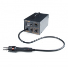
Finally, here are some of the products we used to analyze the device:
