DigitalSandbox PicoBoard
 bri_huang
Introduction
-> 

 <-
<-
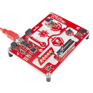
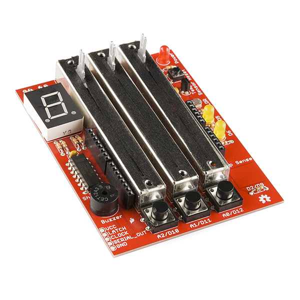
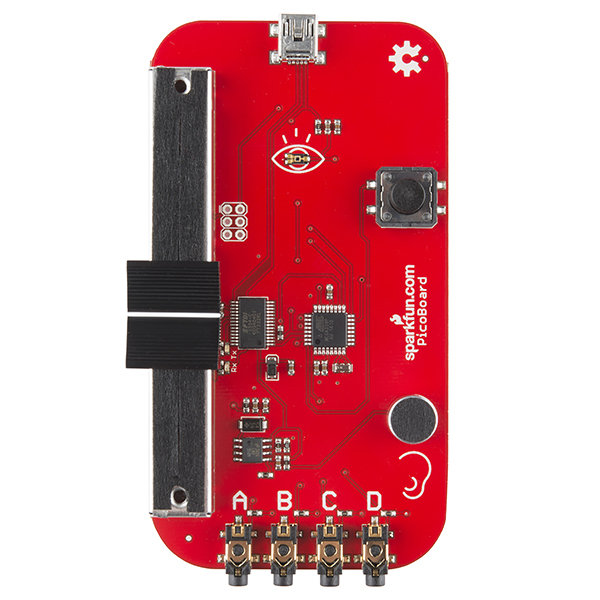
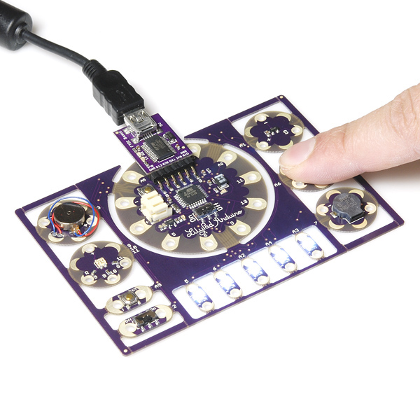
The Digital Sandbox (DS) is a creation that came about as a combination between the best features of the PicoBoard, DangerShield, and the Lilypad Protosnap Development Board. We combined the best of these three great introductory learning platforms to create a single board that has several commonly used peripheral devices -- LEDs, RGB, slider, button, and a variety of sensors.
-> 
 <-
<-
Each of the sensors that are currently on the PicoBoard (slider, button, light, and sound) are also on this board. We thought it would be great to replicate the PicoBoard firmware to work on this device.
Suggested Reading
Uploading Firmware
First, we need to upload firmware to the digital sandbox so that it mimics the same packet information as on the PicoBoard. The original C code for the PicoBoard is available on GitHub, but this code does not work directly in the Arduino programming IDE.
We ported this code base over and made a few adjustments based on the difference of pin configurations on the digital sandbox.
This code reads all of the sensors on the Digital Sandbox, creates data "packets" emulating the PicoBoard, and sends this over to your computer -- to be read in by Scratch.
PicoBoard Arduino Code
language:c
    // DigitalSandboxPico
//
// PicoBoard Firmware modified for the DigitalSandBox
// Arduino Learning Platform.
// Ported over from original C code.
//
// Modified by: Brian Huang, Sparkfun Electronics
// Date:  August 7, 2014

#define SCRATCH_DATA_REQUEST 0x01

char request = 0;
unsigned int sensor_value = 0;
char data_packet[2]= "";

int SLIDER = A3; // Slider on DS Board
int SOUND = A2;  // Microphone on DS Board
int LIGHT = A1;  // Light Detector on DS Board
int BUTTON = 12; // Push Button on DS Board

int RA = A0; // Temp
int RB = 2;  // Switch
int RC = 3;  // D3 -- Side Port
int RD = A4; // A4 -- Top Port

void setup()
{
  pinMode(BUTTON, INPUT_PULLUP);  // enable internal pull-up resistor
  pinMode(RB, INPUT_PULLUP);  // enable internal pull-up resistor
  Serial.begin(38400);
}

void loop()
{
  request = Serial.read();
  if(request == SCRATCH_DATA_REQUEST)
  {
    // send the ID packet
    buildScratchPacket(data_packet, 15, 0x04);
    sendScratchPacket(data_packet);

    // Do not change the order of this sequence. Scratch expects the data
    // to be organized in this order.

    //Read/Report channel 0 (Resistance-D)
    sensor_value=analogRead(RD);
    buildScratchPacket(data_packet, 0, sensor_value);
    sendScratchPacket(data_packet);

    //Read/Report Channel 1 (Resistance-C)
    sensor_value=analogRead(RC);
    buildScratchPacket(data_packet, 1, sensor_value);
    sendScratchPacket(data_packet);

    //Read/Report Channel 2 (Resistance-B)
    sensor_value=1023*digitalRead(RB);
    buildScratchPacket(data_packet, 2, sensor_value);
    sendScratchPacket(data_packet);

    //Read/Report Channel 3 (Button)
    sensor_value = 1023*(1 - digitalRead(BUTTON));
    buildScratchPacket(data_packet, 3, sensor_value);
    sendScratchPacket(data_packet);

    //Read/Report Channel 4(Resistance-A)
    sensor_value=analogRead(RA);
    buildScratchPacket(data_packet, 4, sensor_value);
    sendScratchPacket(data_packet);

    //Read/Report Channel 5(LIGHT)
    sensor_value=1023 - analogRead(LIGHT);
    buildScratchPacket(data_packet, 5, sensor_value);
    sendScratchPacket(data_packet);

    //Read/Report Channel 6(Sound)
    sensor_value=analogRead(SOUND);
    buildScratchPacket(data_packet, 6, sensor_value);
    sendScratchPacket(data_packet);

    //Read/Report Channel 7(Slider)
    sensor_value=analogRead(SLIDER);
    buildScratchPacket(data_packet, 7, sensor_value);
    sendScratchPacket(data_packet);
  }
}

void buildScratchPacket(char * packet, int channel, int value)
{
  char upper_data=(char)((value&(unsigned int)0x380)>>7);   //Get the upper 3 bits of the value
  char lower_data=(char)(value&0x7f);   //Get the lower 7 bits of the value
  *packet++=((1<<7)|(channel<<3)|(upper_data));
  *packet++=lower_data;
}

void sendScratchPacket(char * packet)
{
  Serial.write(*packet++);
  delayMicroseconds(400);
  Serial.write(*packet++);
  delayMicroseconds(400);
}
Copy-paste this code into your Arduino IDE. Select either Lilypad w/ ATMega328 as your board type or Digital Sandbox (if you are using our version of Arduino).
Using Scratch
Scratch is an amazing platform for teaching an introduction to programming. It uses simple color-coded blocks that snap together to create programs or "scripts." It is designed with kids in mind, but the features and functionality of Scratch are extensive enough for you to create your own data-logging dashboards, arcade-style games, or full-length animations. Once you've uploaded the "Picoboard Arduino Code," the Digital Sandbox will work identically to the PicoBoard in Scratch.
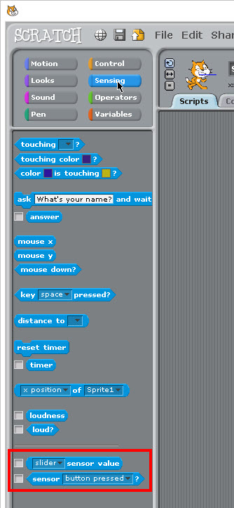
To use the PicoBoard Sensor Blocks, click on the blue Sensing Palette:

At the very bottom of the list, there are two blocks that we can use. One is (slider sensor value) and the other one is a boolean/logic block < sensor button pressed ? > All of the sensors on the PicoBoard (Digital Sandbox) return a value from 0 to 100. It is a scaled value where 0 V ==> 0 and 5 V ==> 100 in the Scratch environment.
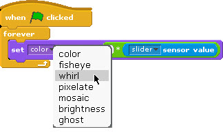
To help us get started, I like to just make a real quick and simple test script using just these four blocks:
Connect / assemble these blocks into a simple program like this:
Test it out!
Click the green flag and see what happens. The color of Scratch the cat should change as you move the slider back and forth. You should see the cat change from Orange --> Yellow --> Green --> Blue.
It seems like we're missing some of the colors. A little digging into the documentation on Scratch shows that the set color effect block operates on a scale of 0 - 200. So, to get the full range, we need to multiply the sensor value by 2. Grab a multiply block from the math operators:

Then, re-assemble the blocks so that it looks like this:
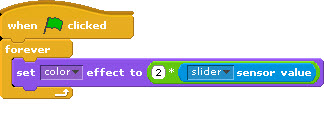
Click the green flag and try it again! How many colors does Scratch go through now?

Play around with other effect options and features. You can tie these to any of the sensors on the PicoBoard (Digital Sandbox) -- Slider, Light, or Sound. We tied the temperature to the Resistance-A sensor - which is also a range of values from 0 to 100.
Reporting Temperature
Using the temperature scale on the Digital Sandbox is pretty simple - it does require a little math, though. Looking at the datasheet on the temperature sensor on this board TMP36 can be daunting, but what we care about is this:
"The TMP36 is specified from −40°C to +125°C, provides a 750 mV output at 25°C, and operates to 125°C from a single 2.7 V supply." and "Both the TMP35 and TMP36 have an output scale factor of 10 mV/°C."
Translation
The TMP36 outputs a voltage that varies linearly with the temperature. Because it is linear, we can start with our favorite equation from Algebra I -- the general equation for a line:
The proportionality (ratio) between voltage and temperature is 10 mV/°C, but we want our slope in units of °C/mV. So, if we take the reciprocal of 10 mV/°C, this is 0.1 °C/mV. It's the same proportion, and it has the correct units. That's our slope!
The intercept point requires a little math. Using the information that says "provides a 750 mV output at 25°C," we can find the intercept point.
Final Equation
In Scratch
In Scratch, the voltage is scaled from 0 to 100. So -- let's see how this works:
Looking at this, I see a lot of decimals, multiplication by 1000's and divide by 100s. It seems like we should be able to simplify this. First, let's simplify the divide by 100 and multiply by 5000.
Next, multiply the 0.1 by the 50 and simplify to:
And, in Scratch -- this looks like:

Sample Scratch Script
We created a little sample script to show all of the features all in one example. Feel free to use this, take parts of it, or re-mix it into your own new program. It changes the sprite based on the light input, the slider value, and the sound level.
The sprite will also walks back and forth if you flip the slide switch to the ON (1) position and will change color (and play a sound) when you push the button. Play around with this example. We're sure you'll come up with other fun ideas too!
Click here to download a copy of the file to run on your own computer.
Going Further
The DigitalSandbox Picoboard is a great start to programming and interacting with sensors, but it only allows you to read input values into Scratch and it does not allow for us to control actuators or affect OUTPUTS.
If you're interested in extending this to more than just reading sensors, try Scratch4Arduino or ArduBlock. We have an entire series of activities and experiments built around Ardublock using the Digital Sandbox here.