$27.50
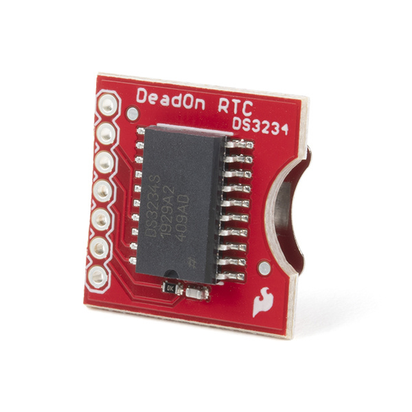
The SparkFun DeadOn RTC Breakout is a simple breakout board for the DS3234 real-time clock (RTC) IC. The DS3234 can accurately keep track of seconds, minutes, hours, days, months, and years, so your microcontroller doesn't have to. It even features a pair of configurable alarms. The DeadOn RTC is perfect for clocks, calendars, or any other time-keeping project.
Communication between a microcontroller and DS3234 is achieved using a four-wire SPI interface. When it's not powered via a primary source, the chip can be set to run on a backup battery -- keeping its programmed time for many years to come.
This tutorial serves as a general introduction to the DS3234 and the SparkFun DeadOn RTC Breakout. It covers both the hardware and firmware requirements of the breakout -- documenting both example wiring and Arduino code for the chip.
You'll need a handful of extra parts to get the DeadOn RTC up-and-running. Below are the components used in this tutorial, if you want to follow along.
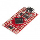
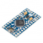
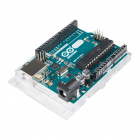
A microcontroller that supports SPI is required to communicate with the DS3234 and relay the RTC's data to the user. The SparkFun RedBoard or Arduino Uno are popular options for this role, but just about any microcontroller development board should work. (The example code in this tutorial uses an Arduino library, if that serves as any extra motivation to go with an Arduino.)

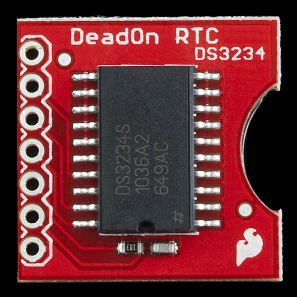
Six or seven jumper wires and a breadboard help interface the RTC to your Arduino. And to insert the breakout into the breadboard, you'll need to solder headers to the pins. (Don't forget a soldering iron and solder!)
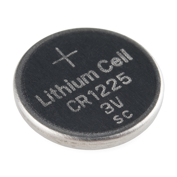
Finally, the DeadOn RTC Breakout does not include a 12mm Coin Cell Battery. Plugging a coin cell in will afford your RTC years-and-years of time-keeping goodness.
The SparkFun DeadOn RTC Breakout is a very beginner-friendly breakout board. There are, however, still a few concepts you should be familiar with. If any of the tutorial titles below sound foreign to you, consider giving them a look-through:
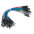
The DeadOn RTC Breakout surrounds the DS3234 with all of the components it needs to count time, communicate, and maintain power. The communication and power pins are all broken out to a single, 7-pin header. The top side of the board houses the IC itself and a couple passives to support it:
While the bottom side of the breakout labels the pins and mounts the 12mm coin cell battery holder:
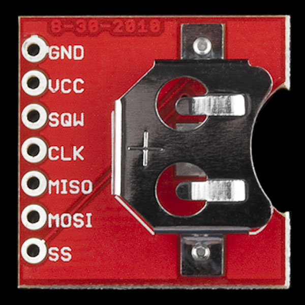
The seven pin breakouts on the board provide access to the communication interface, power supply, and the square-wave/interrupt output of the DS3234:
| Pin Label | Input/Output | Description |
|---|---|---|
| GND | Supply Input | Ground (0V) supply |
| VCC | Supply Input | DS3234 VCC power supply input |
| SQW | Output | Configurable square-wave output Alarm 1 and/or Alarm 2 interrupt output |
| CLK | Input | SPI clock input |
| MISO | Output | SPI master in, slave out |
| MOSI | Input | SPI master out, slave in |
| SS | Input | SPI active-low chip select |
CLK, MISO, MOSI, and SS make up the DS3234's SPI interface. All four need to be connected to your microcontroller's I/O pins to allow communication between the chips. Use of the multi-talented SQW pin is optional, but it can come in very handy if you're using alarms or need an extra time-keeping output. More on that and the power supply pins below.
The Deadon RTC breakout board does not include any voltage regulation, so power supplied to the "VCC" pin should be kept within the DS3234's (wide) recommended operating range: 2.0 to 5.5V. Fortunately, the breakout should work with either 3.3V or 5V development boards!
The chip is designed to be as low-power as possible. While its powered at 5V, during communication bursts, the chip may consume upward of 400-700µA, but it will usually run closer to 120µA. When the primary power supply is removed and the chip is running off its backup battery, it will consume around 2µA.
Assuming it has capacity of 47mAh, a fully charged 12mm coin cell battery can keep the DS3234 running for up to 2.68 years, if the chip consumes an average 2µA!
(47mAh / 2µA = 23500 hours = 979.17 days = 2.68 years)
One of the DS3234's most unique features is its pair of configurable alarms: appropriately named "Alarm 1" and "Alarm 2." The higher-resolution alarm 1, can be set to trigger on any second, minute, hour, and/or day/date combination, while alarm 2 can monitor anything from minutes to days/dates. With every second that passes, the DS3234 compares the time with any alarms that may be set. If everything matches, the chip sets a flag to indicate that one, or both, of the alarms has triggered.
Aside from its SPI pins, the DS3234 also features a very versatile pin, labeled "SQW." This pin can be configured as either a square wave output (with output frequencies ranging from 1Hz to 8.192kHz), or as an active-low interrupt output, indicating an alarm has been triggered.
In order to use the SQW pin as an output or interrupt, it must be connected to a pull-up resistor. A 10kΩ resistor, connected between SQW and VCC, or your microcontroller's internal pull-up resistors should do the job.
Before you can insert the DeadOn RTC Breakout into a breadboard, or otherwise connect it to your microcontroller, you'll need to solder something to the 7-pin header. If you plan on breadboarding with the chip, we recommend straight male headers. Female headers or even a few strips of wire are other good options.
If you're soldering headers, you may want to insert the pins into the "top" side of the board -- maintaining access to the battery and a good view of the labels.
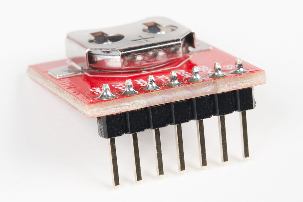
Conveniently, the header's shroud is about the same height as the DS3234, so it shouldn't interfere with breadboard-plugging.
The DeadOn RTC Breakout does not ship with a 12mm coin cell, but the battery is recommended -- without it, the RTC will lose track of time whenever power is lost. When inserting the battery, make sure the "+" sign is facing up -- it should touch the top of the battery holder.
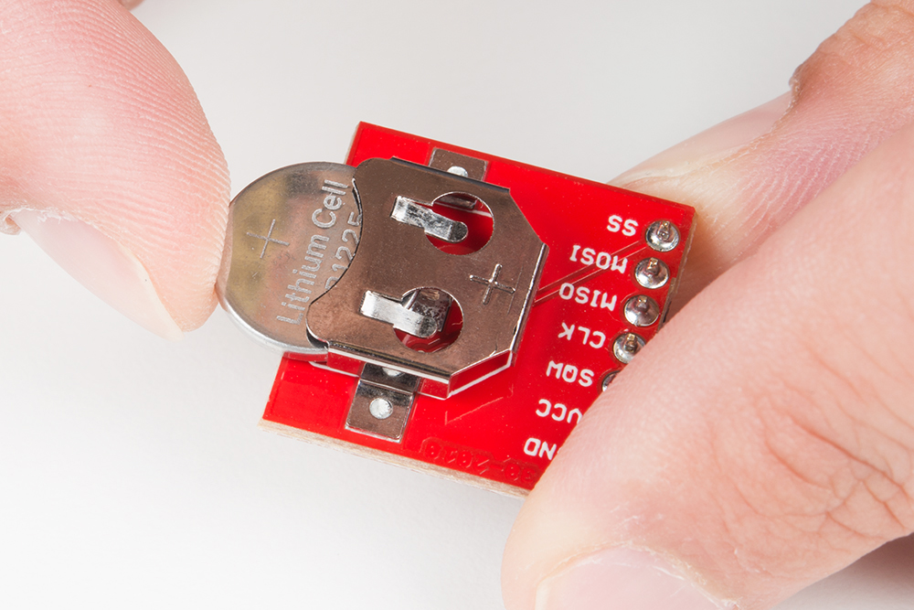
Hopefully you won't have to remove and replace that battery for a good many years!
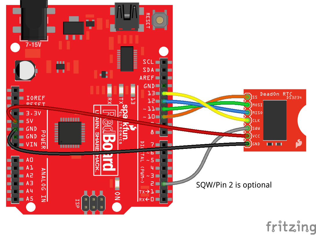
The DS3234's SPI interface means, to interface with the chip, you'll need at least six wires between your microcontroller and the breakout board: power, ground, master-in/slave-out (MOSI), master-out/slave-in (MISO), serial clock (SCLK), and slave-select (SS).
Here is an example hookup diagram demonstrating how to hook the board up to an Arduino Uno. The diagram also connects SQW to the Arduino, using the pin as an interrupt output. This wire is optional, but you'll have to (very slightly) modify the example code if it's not connected.
We've written an Arduino library for the DS3234, which takes care of all of the SPI communication, bit-shifting, register-writing, and clock-managing; it even sets the time of your RTC automatically! Grab the most recent version of the library from our SparkFun_DS3234_RTC_Arduino_Library GitHub repository, or click the link below:
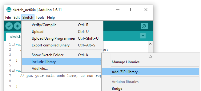
Then follow along with our How to Install an Arduino Library tutorial for help installing the library. If you download the library's ZIP file, you can use Arduino's "Add ZIP Library..." feature to install the source and example files with just a couple clicks.
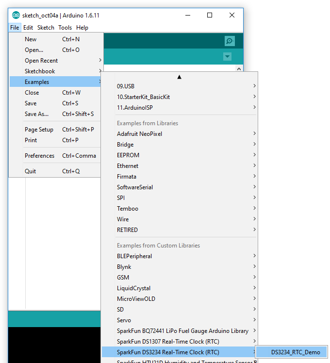
Once you've downloaded the library, open the DS3234_Demo by navigating to File > Examples > SparkFun DS3234 Real Time Clock (RTC) > DS3234_RTC_Demo:
If you don't have the SQW pin connected -- used in this example as the alarm interrupt -- comment out the #define INTERRUPT_PIN 2 line, toward the top of the sketch. The loop will instead poll the DS3234 for the alarm status.
Make sure your board and port are set correctly and upload! Then click over to the Serial Monitor. Make sure the baud rate is set to 9600 bps, and you should begin to see the seconds fly by:
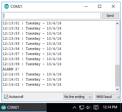
The alarms are configured to ring every thirty seconds -- alarm 2 triggering at the top of the minute, and alarm 1 triggering at 30-seconds on the minute.
The example demonstrates almost all of the DS3234's functionality. Here's a quick primer on how to incorporate the library into your project:
To begin, make sure you include the SparkFunDS3234RTC.h library. Above that, you'll need to include SPI.h the Arduino SPI library:
language:c
#include <SPI.h>
#include <SparkFunDS3234RTC.h>
The DS3234 library defines an object conveniently named rtc to access all of the functions and data of the RTC module. To initialize the RTC, begin by calling the rtc.begin(<cs_pin>) function in your setup() area:
language:c
#define DS13074_CS_PIN 10

void setup()
{
    ...
    rtc.begin(DS13074_CS_PIN);
    ...
}
The begin() function takes one parameter -- the SPI slave-select pin, "SS." In our example circuit we connected SS to Arduino pin 10, though it can be connected to any other pin.
Once the RTC is initialized, you can set the RTC's time. There are a few options here. We recommend using either the rtc.autoTime() function, which sets the RTC's clock your computer's date and time (based on the time of compilation), or rtc.setTime(<second>, <minute>, <hour>, <day>, <date>, <month>, <year>), which allows you to precisely set the clock.
The demo example defaults to using rtc.autoTime(), which sets your RTC's time and date to your computer's time and date. It may end up being a handful of seconds off, as time continues ticking while the code is uploaded.
Once the RTC's time and date register have been set – using either the autoTime or setTime functions – you may never have to set the clock again!
Consider commenting out the autoTime or setTime entirely once you've perfectly configured the clock.
If you want to manually set the time, use the setTime() function. For example:
language:c
// Set to 13:37:42 (1:37:42 PM)
int hour = 13;
int minute = 37;
int second = 42;
// Set to Monday October 31, 2016:
int day = 2; // Sunday=1, Monday=2, ..., Saturday=7.
int date = 31;
int month = 10;
int year = 16;

rtc.setTime(second, minute, hour, day, date, month, year);
The RTC defaults to 24-hour mode, but does support 12-hour mode with an AM/PM bit. If you’d like to use 12-hour mode, simply call rtc.set12Hour() (or rtc.set24Hour() to switch back to 24-hour mode).
To set the time in 12-hour mode, an extra parameter – AM or PM – should be added after ther `hour` variable. For example:
setTime(14, 42, 7, PM, 1, 28, 12, 16); // Set time to 7:42:14 PM, Sunday December, 28
Once the clock is set, it will automatically begin incrementing second-by-second, minute-by-minute, year-by-year. To read the time and date values, begin by calling rtc.update(). This will command the DS3234 to read all of its data registers in one, fell swoop.
After the RTC data is updated, you can read those updated values by calling rtc.hour(), rtc.minute(), rtc.second(), etc. For example:
language:c
rtc.update(); / Update RTC data

// Read the time:
int s = rtc.second();
int m = rtc.minute();
int h = rtc.hour();

// Read the day/date:
int dy = rtc.day();
int da = rtc.date();
int mo = rtc.month();
int yr = rtc.year();
"Day" is the "day of the week", e.g. Sunday, Monday, Tuesday... rtc.day() returns an integer between 1 and 7, where 1 is Sunday and 7 is Saturday (sorry week-starts-on-Monday truthers). Alternatively, you can call rtc.dayChar() or rtc.dayStr(), which return a character or full-string representation of the day of the week.
The DS3234's pair of alarms can be set with the setAlarm1(<second>, <minute>, <hour>, <date>, <day/date>) and setAlarm2(<minute>, <hour>, <date>, <day/date>) functions. Alarm 1's resolution can go as low as seconds, while Alarm 2 is limited to minutes.
All variables in the setAlarm functions are optional. If they're not explicitly set, a variable will default to 255, and will be masked out of the alarm checking. An alarm triggers whenever any of its non-masked-out variables exactly match the current time and/or day/date.
Here are a few alarm-setting examples, to show off how the functions can be used:
language:c
// With no values passed, the alarms will trigger every second/minute:
setAlarm1(); // Alarm 1 triggers every second
SetAlarm2(); // Alarm 2 triggers every minute
// With one value passed, the alarms will trigger on second/minute matches:
setAlarm1(25); // Alarm 1: whenever SECONDS are 25 (e.g. 2:01:25, 2:02:25, etc...)
setAlarm2(45); // Alarm 2: whenever MINUTES are 45 (e.g. 13:45, 14:45, etc...)
// With two values passed, alarms will trigger on second/minute or minute/hour matches:
setAlarm1(19, 15); // Alarm 1: whenever SECONDS are 19 and MINUTES 15 (e.g. XX:15:19)
setAlarm2(0, 30); // Alarm 2: midnight:30
// Three values passed: Alarm 1 triggers at specific time, Alarm 2 triggers at time/day-of-month
setAlarm1(17, 33, 19); // Alarm 1: 19:33:17 (7:33:17 PM)
setAlarm2(0, 1, 2); // Alarm 2: 1:00 on the 2nd day of the month
// Four values passed:  Alarm 1 triggers at specific time/day-of-month, Alarm 2 triggers at time/day-of-week
setAlarm1(11, 11, 11, 19); // Alarm 1: 11:11:11 on the 19th day of the month
setAlarm2(17, 7, 1, true); // Alarm 2: 7:17:00 on a Monday (1)
// If last parameter in alarm 1 or alarm 2 is true, it will alarm on a weekday match
setAlarm1(4, 5, 6, 7, true); // Alarm 1: 6:05:04 on Saturday (7)
If you're using the DS3234 in 12-hour mode, you'll need to add an AM or PM after the `hour` variable. For example:
setAlarm1(45, 30, 2, PM); // Set alarm 1 for 2:30:45 PM
setAlarm2(0, 6, AM; // Set alarm 2 for 6:00 AM
To monitor the state of either alarm, call the rtc.alarm1() and rtc.alarm2() functions. These will check a status flag in the DS3234 and return true if the alarm has triggered.
language:c
if (rtc.alarm1())
    Serial.println("ALARM 1 is triggered!");
if (rtc.alarm2())
    Serial.println("ALARM 2 is triggered!");
Finally, to use the SQW pin as an interrupt, call the rtc.enableAlarmInterrupt(); function. The interrupt is active-low, which means you'll want to pull the pin high through a resistor (or an internal pull-up). When the pin reads low, an interrupt has occurred, which means its time to read either/both of the alarm() functions.
For more on using the SparkFun DS3234 Arduino Library consider reading through the header file, which documents all of the Arduino sketch-available functions.
For more on the DeadOn RTC Breakout and the Maxim DS3234, check out the links below:
Now that your Arduino is ticking away the seconds, what project are you going to create with the DeadOn RTC? Need some inspiration, check out some of these related tutorials:
Or check out some of these blog posts for ideas:
learn.sparkfun.com | CC BY-SA 3.0 | SparkFun Electronics | Niwot, Colorado