Buck-Boost Hookup Guide
 Alex the Giant, Ell C
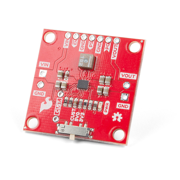
Hardware Overview
The Buck-Boost board is centered around the TPS63070 Buck-Boost converter, which will take your input power and either regulate the output voltage up or down to your set output voltage. In this section we'll take a closer look at how the converter works and how you can incorporate into your next project.
Power Pins
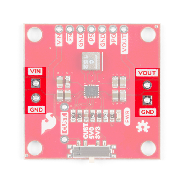
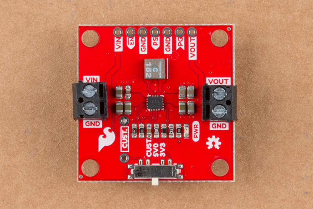
The Buck-Boost board has an input voltage range of 3-16V. You can supply power by either soldering wires directly to the board or by using our 3.5mm screw terminals.
The output is adjustable from 2.5-9V using the single-pole-triple-throw switch. The board is configured with two of the more common voltages you might use, 3.3V and 5V, but there's a unpopulated PTH resistor to allow for setting a specific voltage.
Setting The Output Voltage
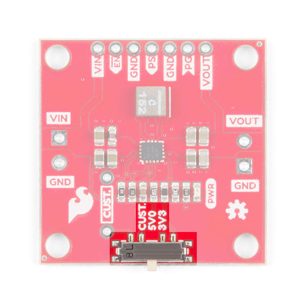
The output voltage of the Buck-Boost is set by voltage divider connected to the feedback pin. The Buck-Boost board has one fixed resistor at 68.1kΩ and the switch changes the second resistor between VOUT and the feedback pin. To change the output voltage, move the switch to one of the three positions for 3.3V, 5V, or CUST. The CUST position is there to allow you to set the voltage to whatever you need by soldering a resistor to the PTH resistor pads highlighted below.
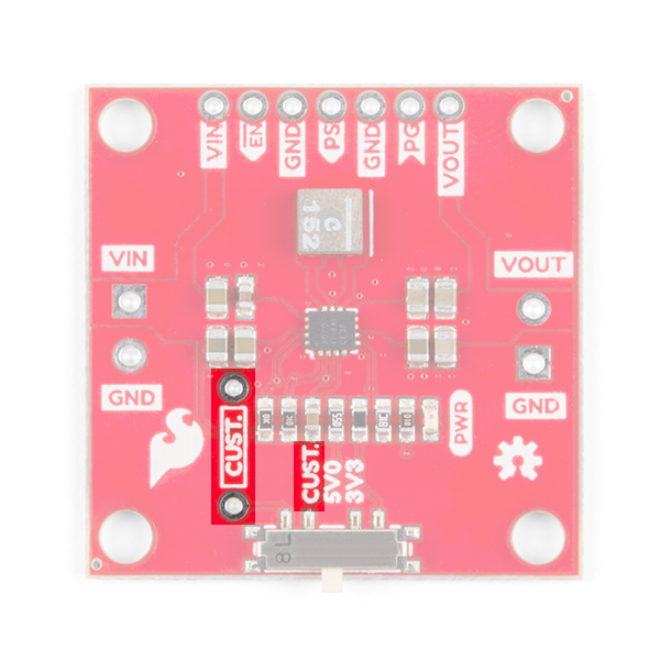
Use the equation below to determine the resistor value needed based on the desired output voltage.

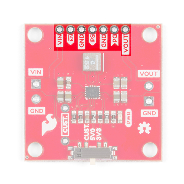
I/O pins
The Buck-Boost board will work out of the box, but if you need a little bit more control, most of the extra pins have been broken out, as shown below.
| Pin | Description |
|---|---|
| VIN | Supply voltage for power stage. Can be used to pass power to the rest of the project, or used to set the logic level. |
| EN | Enable input. Pull high to enable the device. Pull Low to disable the device. Default: HIGH through 10kΩ pull-up resistor to VIN. |
| GND | Ground. Can be used to set I/O pin low. |
| PS | Power Save. Pull low for forced PWM. Pull high for power save mode. In power save mode, the switching frequency will adjust to the most efficient frequency. You can also apply a clock signal to synchronize to an external frequency. Default: HIGH through 10kΩ pull-up resistor to VIN. |
| PG | Power good open drain output. |
| VOUT | Additional buck-boost converter output. |
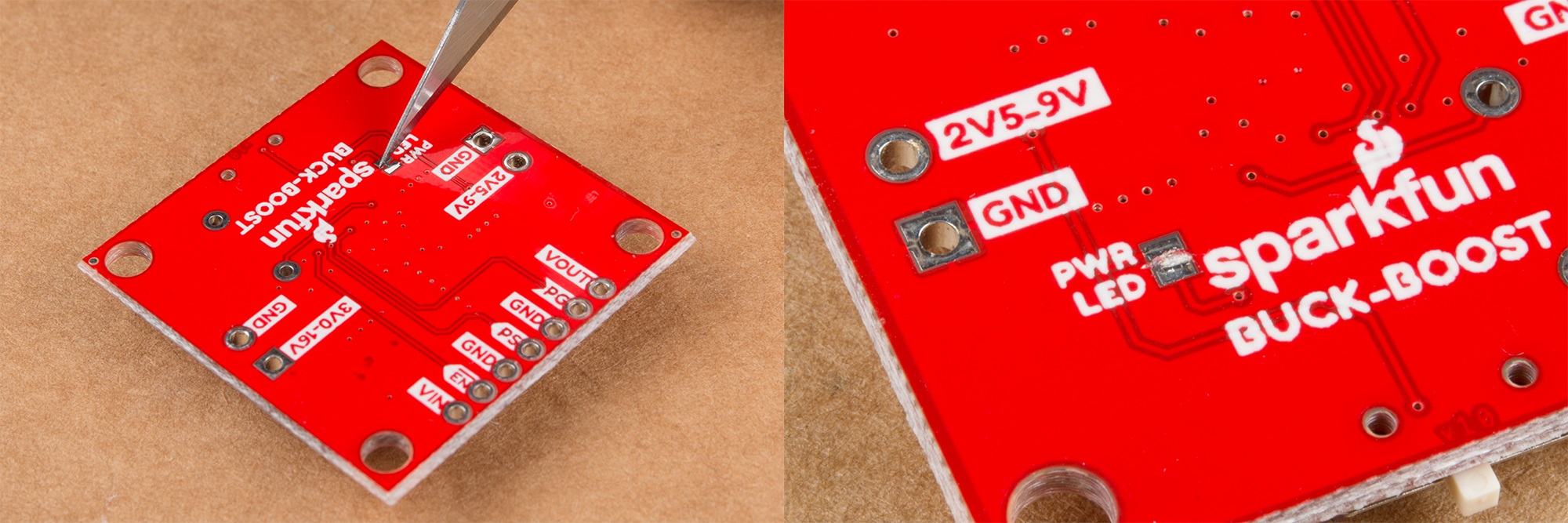
PWR LED
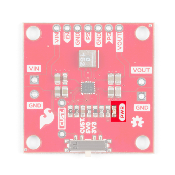
The power LED indicates red when voltage is present on the output pins. Because the LED has a fixed 1k current limiting resistor in series, the brightness of the LED will vary depending on the output voltage. The LED can be disabled by cutting the jumper on the back of the board as shown below.