
$13.21
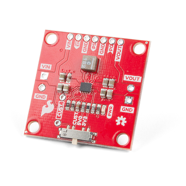
We got tha powah! The Buck-Boost Converter is the latest breakout from SparkFun that allows you to fine tune the amount of power your project receives. It can take an input voltage of anywhere from 3-16V which can then be regulated to an output voltage between 2.5-9V. With the switch on the bottom of the board, you can set the common output voltages of 3.3V and 5V, but we've also broken out a custom setting that allows you to populate a resistor based on your custom voltage needs. What's more, we have broken out the GPIO pins along the top of the board for even more control. Get your boost on!
To follow along with this tutorial, you will need the following materials. You may not need everything, depending on what you have. Add it to your cart, read through the guide, and adjust the cart as necessary.
You may also need a soldering iron, solder, and general soldering accessories.
If you aren’t familiar with the following concepts, we recommend checking out these tutorials before continuing.
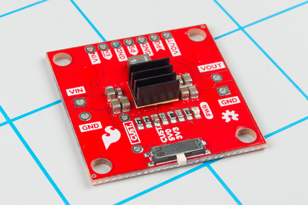
The Buck-Boost board is centered around the TPS63070 Buck-Boost converter, which will take your input power and either regulate the output voltage up or down to your set output voltage. In this section we'll take a closer look at how the converter works and how you can incorporate into your next project.
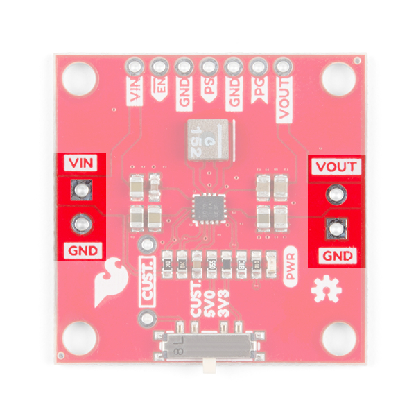
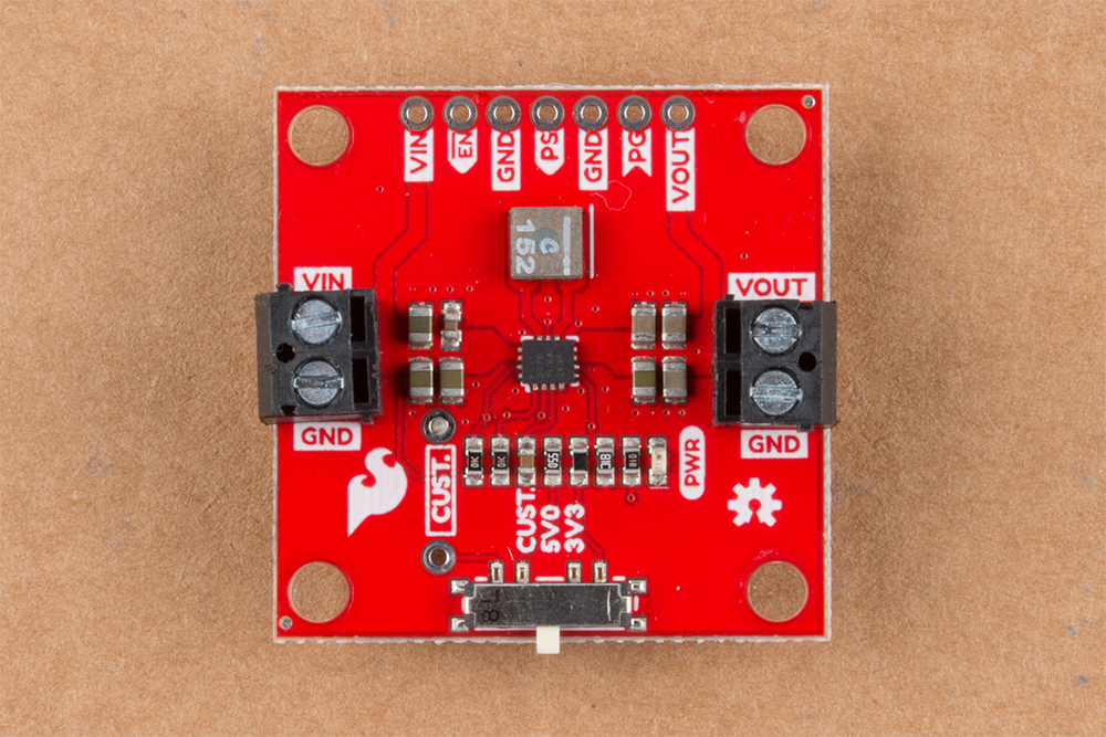
The Buck-Boost board has an input voltage range of 3-16V. You can supply power by either soldering wires directly to the board or by using our 3.5mm screw terminals.
The output is adjustable from 2.5-9V using the single-pole-triple-throw switch. The board is configured with two of the more common voltages you might use, 3.3V and 5V, but there's a unpopulated PTH resistor to allow for setting a specific voltage.
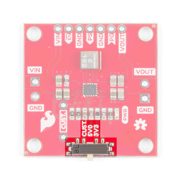
The output voltage of the Buck-Boost is set by voltage divider connected to the feedback pin. The Buck-Boost board has one fixed resistor at 68.1kΩ and the switch changes the second resistor between VOUT and the feedback pin. To change the output voltage, move the switch to one of the three positions for 3.3V, 5V, or CUST. The CUST position is there to allow you to set the voltage to whatever you need by soldering a resistor to the PTH resistor pads highlighted below.
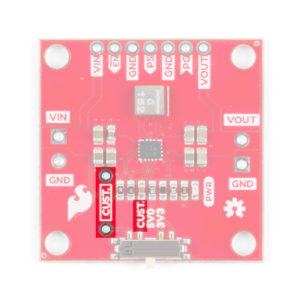
Use the equation below to determine the resistor value needed based on the desired output voltage.

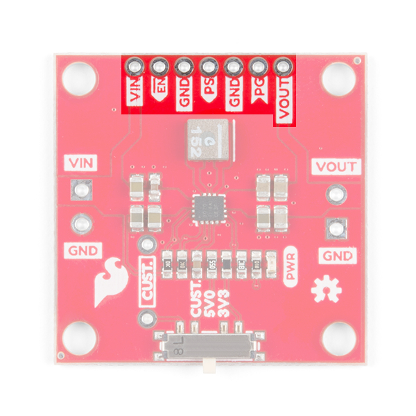
The Buck-Boost board will work out of the box, but if you need a little bit more control, most of the extra pins have been broken out, as shown below.
| Pin | Description |
|---|---|
| VIN | Supply voltage for power stage. Can be used to pass power to the rest of the project, or used to set the logic level. |
| EN | Enable input. Pull high to enable the device. Pull Low to disable the device. Default: HIGH through 10kΩ pull-up resistor to VIN. |
| GND | Ground. Can be used to set I/O pin low. |
| PS | Power Save. Pull low for forced PWM. Pull high for power save mode. In power save mode, the switching frequency will adjust to the most efficient frequency. You can also apply a clock signal to synchronize to an external frequency. Default: HIGH through 10kΩ pull-up resistor to VIN. |
| PG | Power good open drain output. |
| VOUT | Additional buck-boost converter output. |
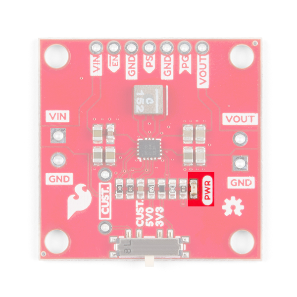
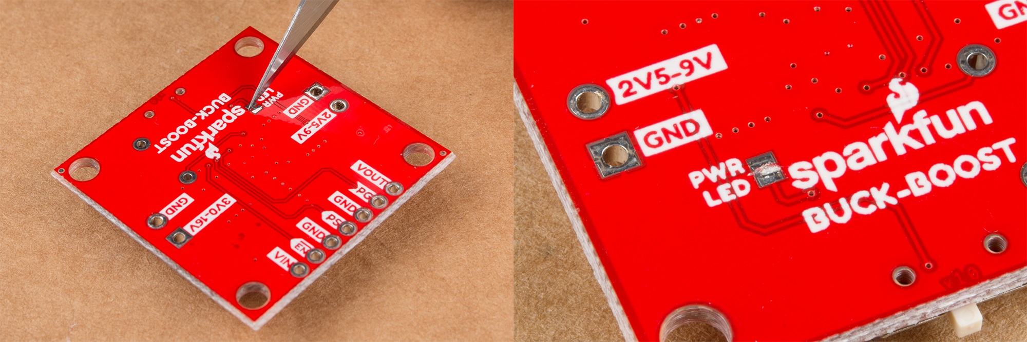
The power LED indicates red when voltage is present on the output pins. Because the LED has a fixed 1k current limiting resistor in series, the brightness of the LED will vary depending on the output voltage. The LED can be disabled by cutting the jumper on the back of the board as shown below.
One of the benefits of the Buck-Boost, aside from boosting the output voltage up from a lower input voltage, is it uses a switching DC/DC converter, which is more efficient than a linear regulator. More efficiency means less energy is wasted in the form of heat. However, that doesn't mean the TPS63070 doesn't get hot under load. The TPS63070 has an operating die temperature range of -40 to +125°C, using the graphs below should provide a good rule of thumb for the maximum output current available at various output voltages as a function of the input voltage.
The temperature was recorded using a FLIR camera with an air temperature of 25°C, with a maximum case temperature of 100°C. Each output voltage graph has a showing the maximum output current both with and without a heatsink.
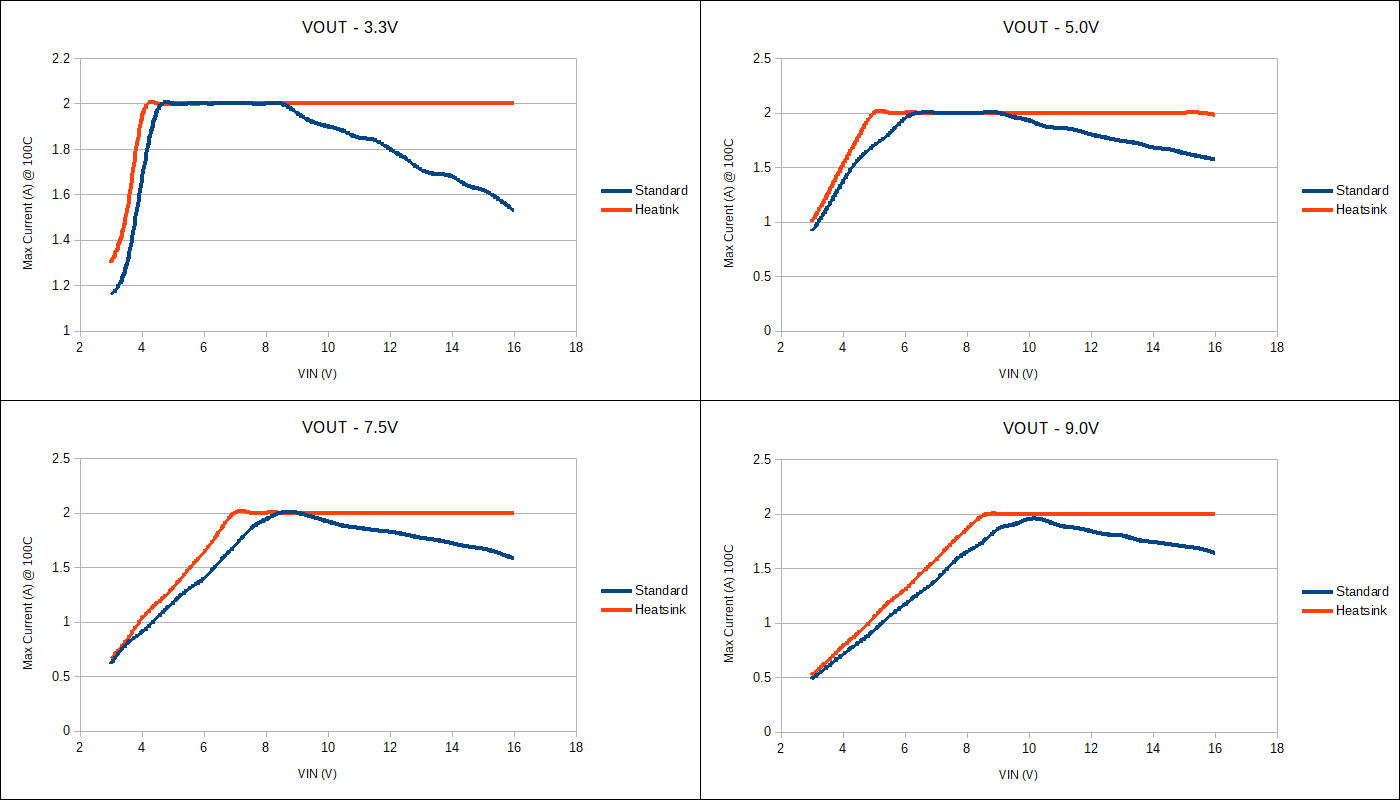
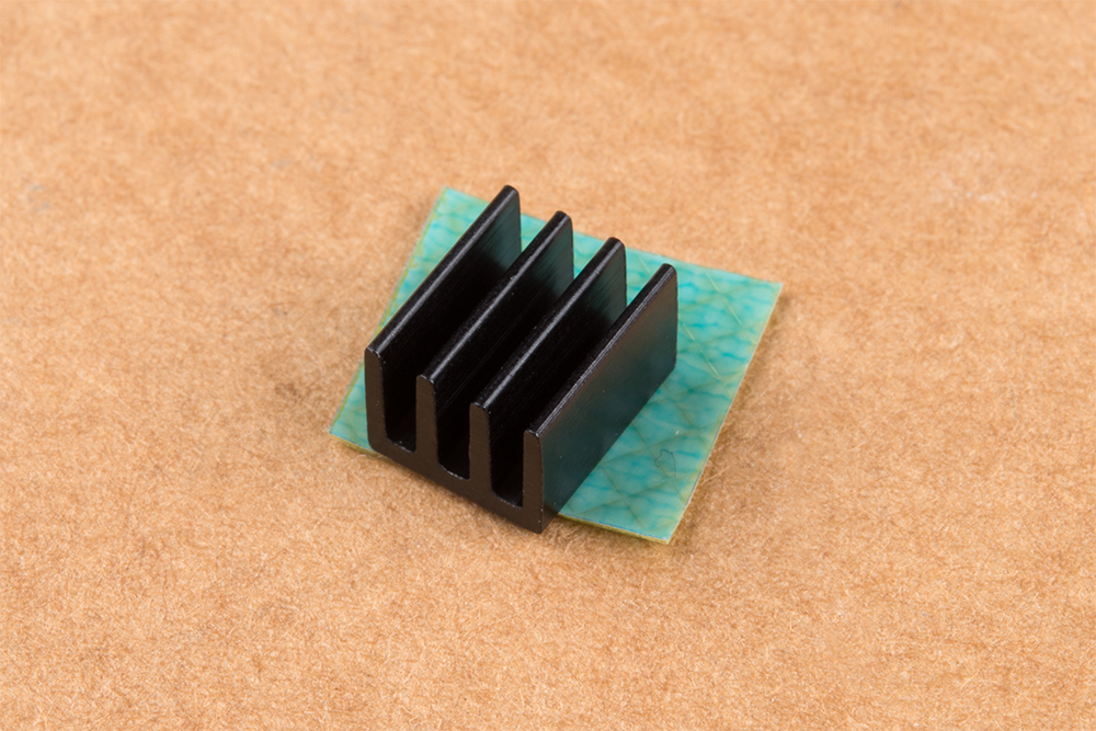
In the maximum output current section, the graphs are shown both with and without a heatsink. The benefit of a heatsink is it provides more surface area for the air to dissipate the heat, which will allow the Buck-Boost board to output the maximum amount of current across a wider input voltage range. To add a heatsink you'll need two of our products: a heatsink (of course), and our thermal tape.
To add a heatsink first cut the thermal tape to rough size:
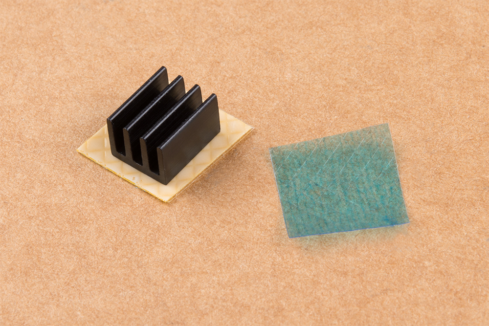
Peel off one of the protective coverings and attach heatsink to thermal tape:
With a hobby knife, follow the perimeter of the heatsink to cut the tape to it's final size:
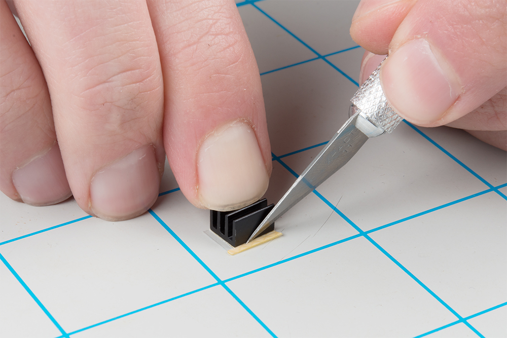
Remove the remaining protective covering of the tape and attach the heatsink to the TPS63070, trying to center the heatsink over the IC:
Depending on the size of the load connected to the output, you may need to wait between when the enable pin is pulled high and the load is connected to the board. The time delay is relatively short (~10ms), but it shouldn't be a problem if the load is <800mA at 3.3V, or <700mA at 5.0V. If the custom resistor is populated to output a voltage greater than 5V, you should be able to leave the load connected if the load is <650mA.
For more information on the Buck Boost, check out some of the links below:
Need more inspiration? Check out these related tutorials!
Or check out this blog post.
learn.sparkfun.com | CC BY-SA 3.0 | SparkFun Electronics | Niwot, Colorado

