Big Easy Driver Hookup Guide
 Toni_K
Hardware Hookup
Connect Motor Coil Wires
You will need to determine the wire pairs for each coil on the motor you plan to use. The most reliable method to do this is to check the datasheet for the motor.
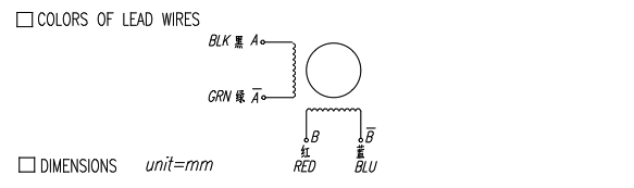
However, if you are using a 4-wire or 6-wire stepper motor, it is still possible to determine the coil wire pairs without the datasheet.
For a 4-wire motor, take one wire and check its resistance against each of the three remaining wires. Whichever wire shows the lowest resistance against the first wire is the pair mate. The remaining two wires should show similar resistance between the two of them.
For a 6-wire motor, you will need to determine which of three the wires go together for one coil. Pick one wire, and test this against all other wires. Two wires should show some resistance between them and the first wire picked, while the other three will show no connection at all. Once the three wires for one coil have been determined, find two of the three that show the highest resistance between them. These will be your two coil wires. Repeat for the second group of three wires.
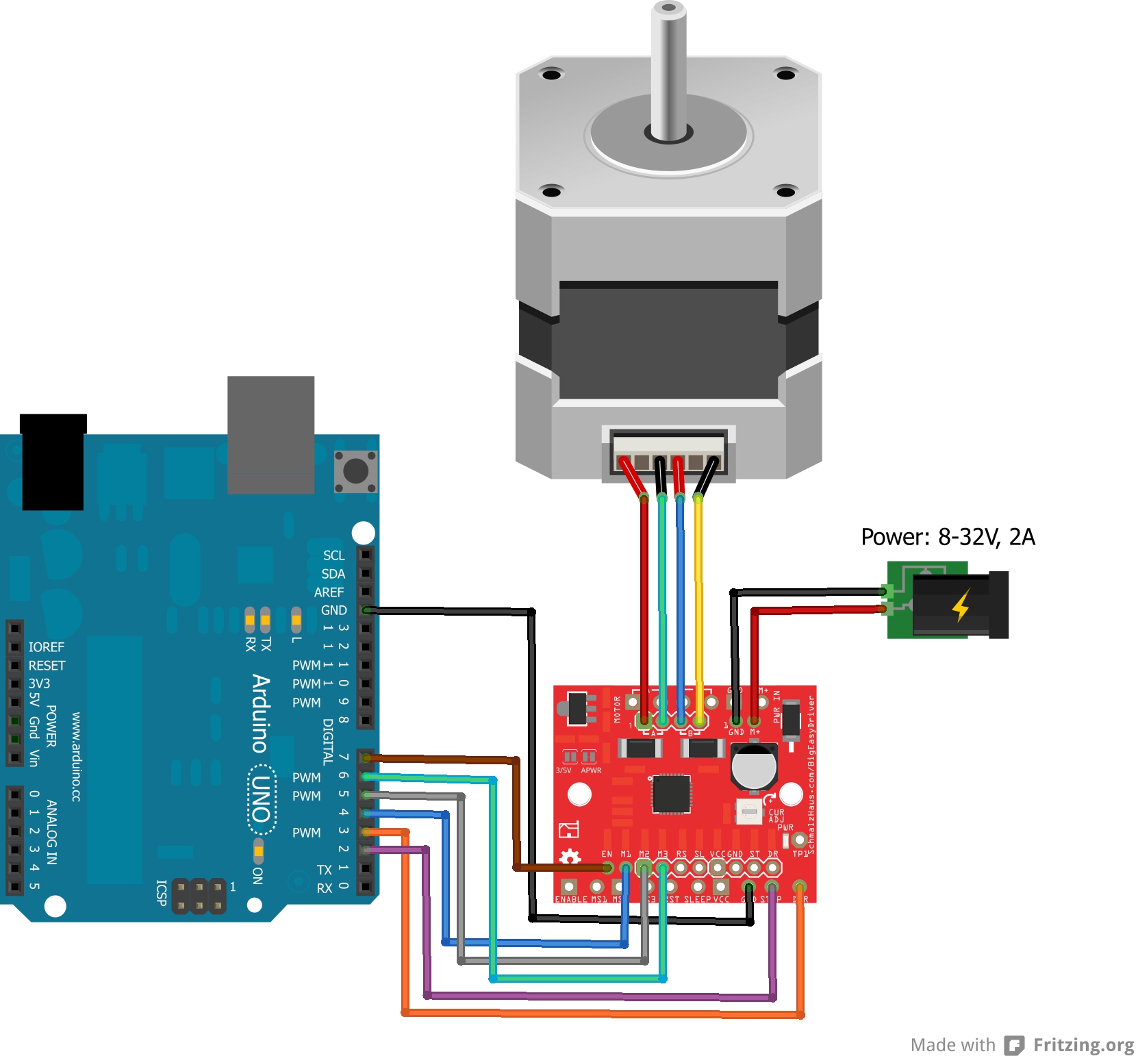
Once you have determined the coil wire pairs, you will need to attach them to the Big Easy Driver. The first coil pair should be plugged into Coil A+ and Coil A-, while the second coil pair plugs into Coil B+ and Coil B-. There is no polarity on the coils, so you don't need to worry about plugging in a coil backwards on the board. In our example, we are using a 4-coil motor. The connections between the Big Easy Driver and motor are as follows.
Big Easy Driver → Motor
- A+ → Red Wire
- A- → Green Wire
- B+ → Blue Wire
- B- → Yellow Wire
Connect a Power Supply
Once your motor is connected, you can then connect a power supply to the Big Easy Driver. You can use any kind of power supply (desktop, wall adapter, battery power, etc.), but verify that whatever choice you go with is capable of providing up to 2A and falls in the range of 8V to 35V.
Power supplies with a current limiting feature: If you use a power supply that has a current limiting feature, you need to either disable that feature, or turn the maximum current level up to a point above what you expect your motor to draw. If your power supply attempts to limit current to the Big Easy Driver, it can damage the board.
Connect the power supply to M+ and GND. REMEMBER to disconnect the power before connecting/disconnecting your motor.
Connect a Microcontroller
For this example, we will be using an Arduino Uno R3. However, any microcontroller that works at 3.3V or 5V logic and has digital I/O will work for this example.
Here are the following pin connections for our example.
Uno → Big Easy Driver
- D2 → STEP
- D3 → DIR
- D4 → MS1
- D5 → MS2
- D6 → MS3
- D7 → ENABLE
- GND → GND
Final Circuit
Once everything is connected, your setup should look like this: