$3.95
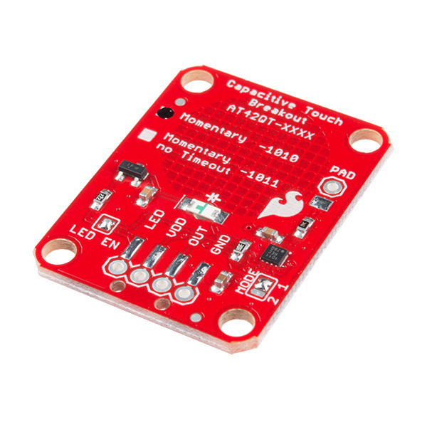
If you need to add user input without using a button, then a capacitive touch interface might be the answer. The AT42QT1010 and AT42QT1011 Capacitive Touch Breakout boards offer a single capacitive touch button with easy-to-use digital I/O pins. For convenience I'll refer to both versions of this board as "AT42QT101X" but I'll refer to each individual version when talking about their differences.
The AT42QT101X is a dedicated, single-button capacitive sense chip. The chip handles monitoring a conductive area for touch. As long as a touch (e.g. from a finger) is detected, the AT42QT101X keeps the output line high. Otherwise, the line is kept low. You just need to provide a power source (1.8V - 5V) and ground for the AT42QT101X to work. SparkFun's breakout board contains an on-board electrode capable of detecting touches. Additionally, a PAD pin is available if you would like to create your own external electrode.
This tutorial will show you how to connect the AT42QT101X Breakout Board to an Arduino along with some example code to read the board's output. Additionally, alternative ways to use the board will be shown, such as mounting it to an acrylic panel and creating your own capacitive sensing pad.
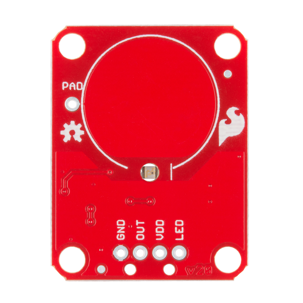
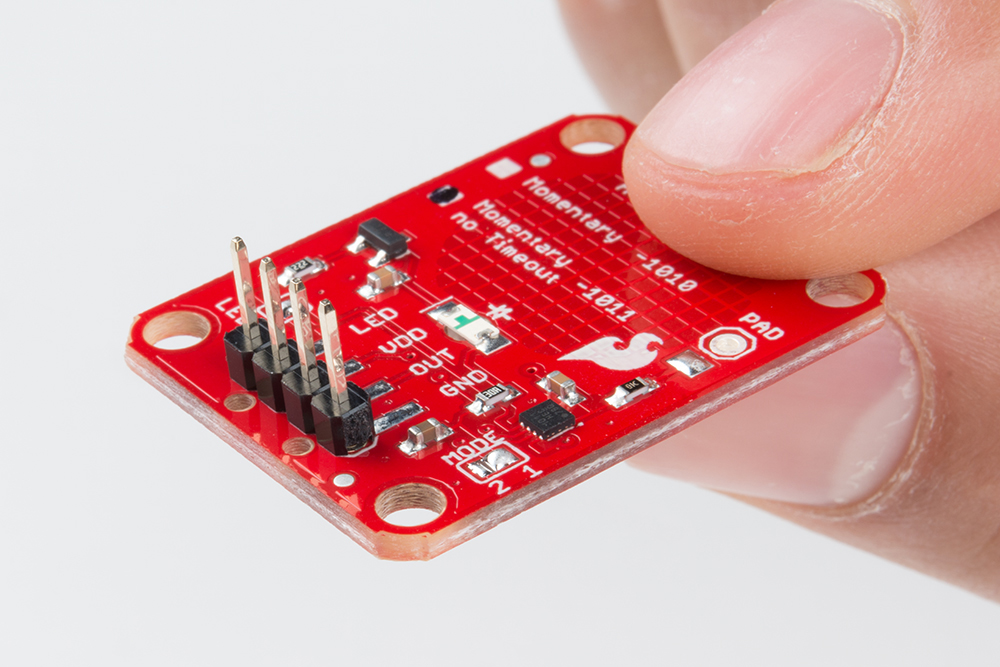
If we look at the front of the board, we see a large, circular pad (the "electrode") and several pins. The on-board electrode will detect touches when pressed with a finger as long as the board is powered.
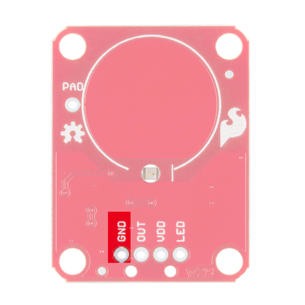
GND should be connected to the ground of the host circuit.
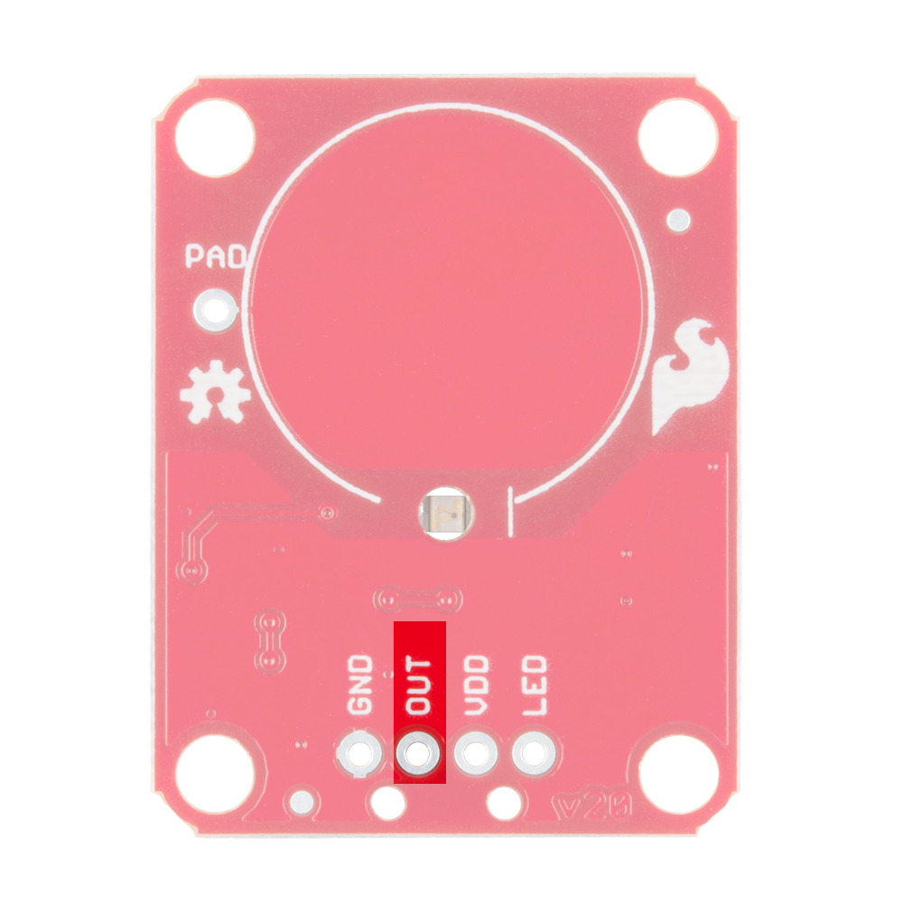
OUT is the output of the AT42QT101X. HIGH on touch, LOW otherwise.
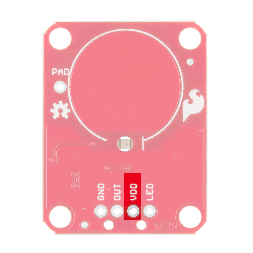
VDD is the power supply for the AT42QT101X and needs to be connected to a voltage between 1.8V - 5V.
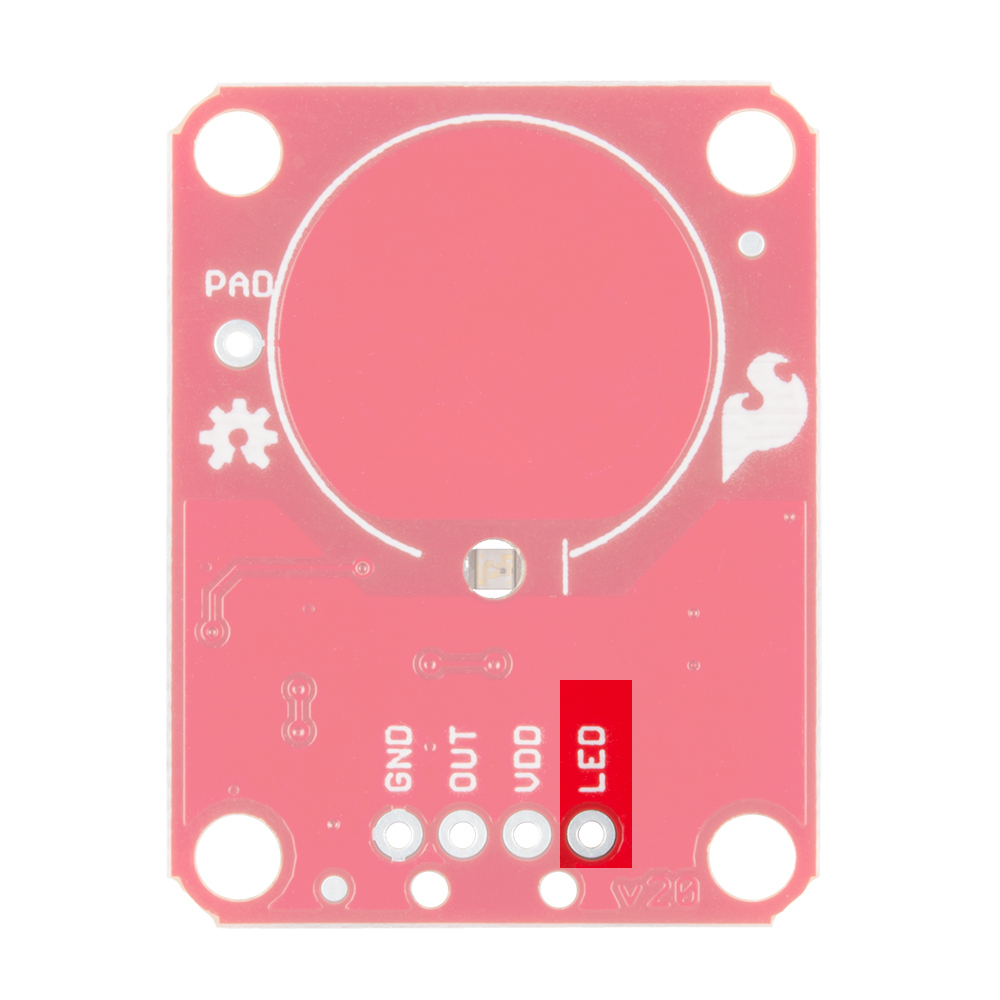
LED controls the operation of the on-board LED. By default, it is connected to the OUT pin. If you de-solder the "LED Enable" jumper on the back side, you can independently control the LED.
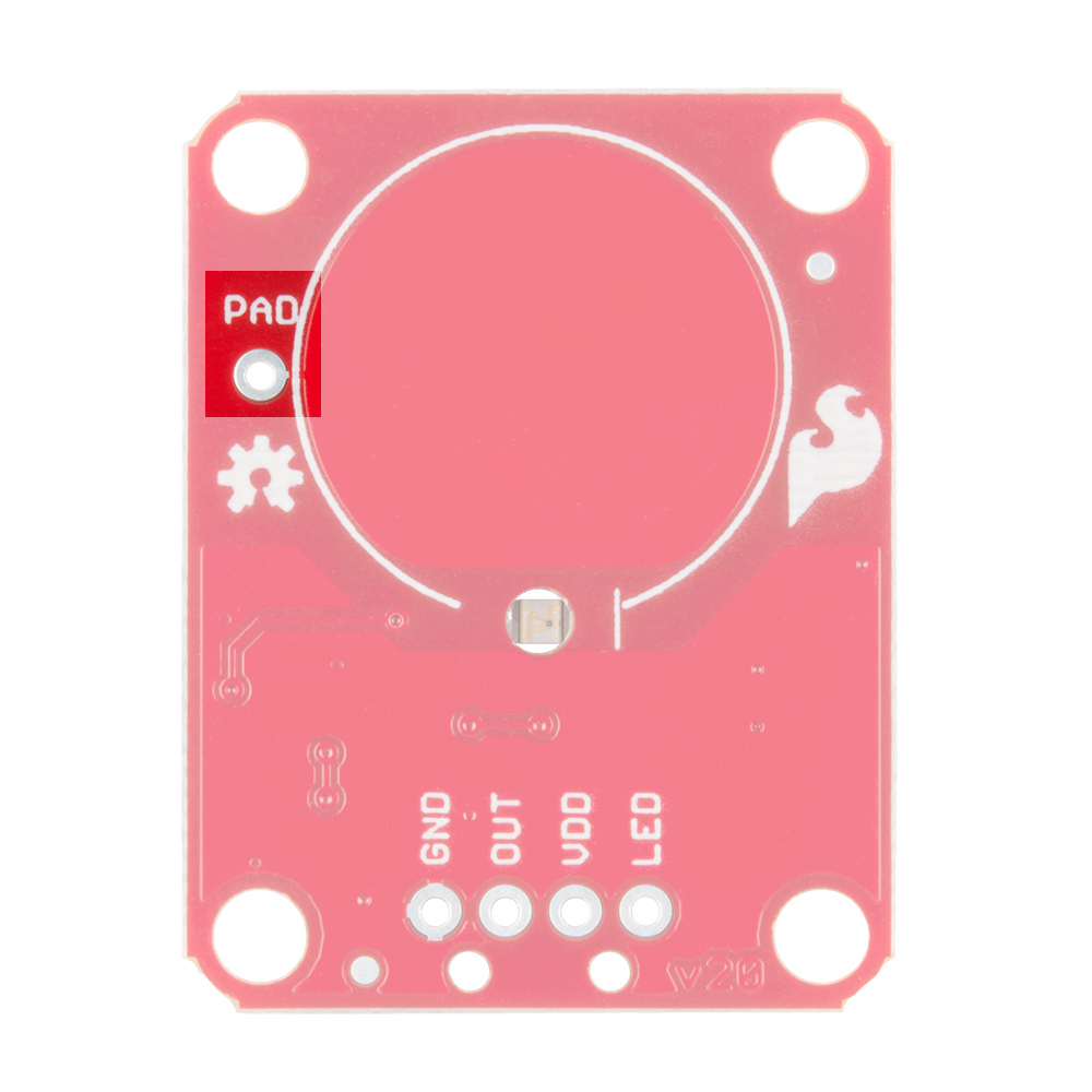
PAD is located in the upper-left corner and allows you to connect to an external electrode. Note that there is a small surface mount pad on the back side by the PAD pin hole. If you want to mount the board flush, you can solder a wire directly to the surface mount pad.
Take a look at the back side of the AT42QT101X. Both versions share the exact same PCB layout but different IC's (lower right "1011").
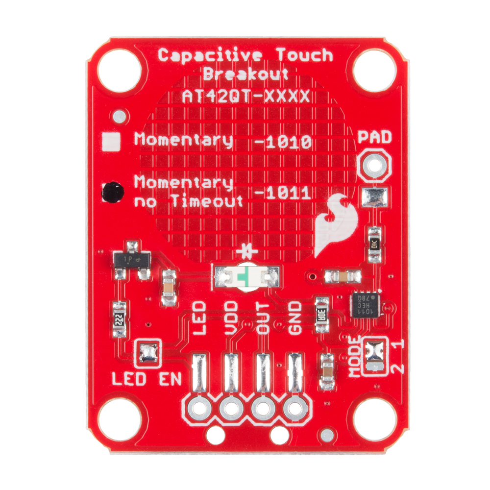
The AT42QT101X chip is located on the right side of the board. It uses a resistor and a capacitor network to adjust the sensitivity of the electrode. High frequency pulses are sent to the pad. When a fleshy object (such as a finger) approaches the pad, it acts like a very small capacitor and changes the shape of the pulses. When the AT42QT101X detects these slight changes, it raises the OUT line to HIGH, indicating a touch is present. The duration of the output depends on the chip that is populated. Once the pulses return to normal, the AT42QT101X drives the OUT line LOW.
The version of your chip is indicated by the small check boxes on the back side. We offer two versions of the same chip: the AT42QT1010 and the AT42QT1011. Both boards function the same with one small caveat: the AT42QT1010 has an internal timeout of ~60 seconds where as the AT42QT1011 does not. Meaning that if you hold your finger to the AT42QT1010's pad for more than 60 seconds than the boards' OUT pin will go low (turn itself off). The difference is small but may be a game changer depending on your project's uses.
The output from the AT42QT101X goes directly to the OUT pin on the board as well as to the transistor (left side), which operates the LED (center of board). By default, the OUT line and LED lines are connected, which means that on a touch, the on-board LED lights up. You can disconnect the LED by de-soldering the jumper labeled "LED Enable." This will cause the LED to no longer light up on a touch, but you can still drive the LED using the LED pin on the board.
On the right side of the board, you will also notice a jumper labeled "Mode" with "1" and "2" markers. By default, the center pad and the "1" pad are connected, which puts the AT42QT101X in "Fast" mode. In Fast mode, the chip is more responsive to touch events but draws 200µA - 750µA in normal operation. If you de-solder this jumper and connect the center pad to the "2" pad, the AT42QT101X will be in "Low Power" mode. In this mode, the chip is slightly less responsive to events but only uses 15µA - 75µA. Keep in mind that the current draw of the IC itself. The LED draws another 30-40mA but can be disabled by removing solder from the "LED enable" solder jumper.
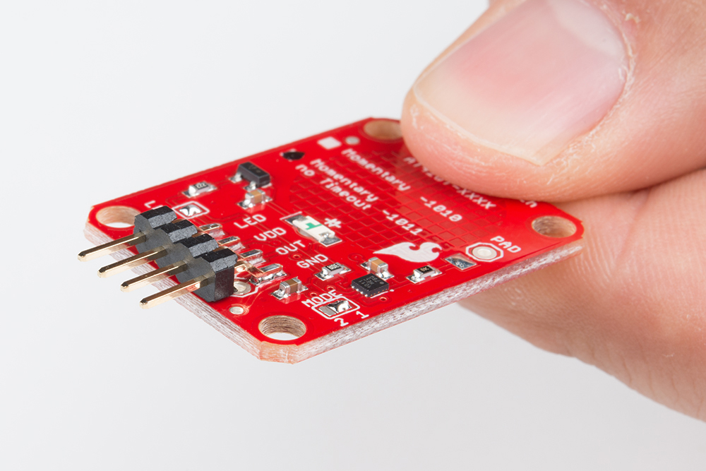
If you are not planning to mount the board flush to a panel, you can solder either wires or break away headers to the 4 header holes on the board.
On the other hand, if you wish to mount the AT42QT101X to a panel, you can solder a 4-pin male header to the SMD pads.
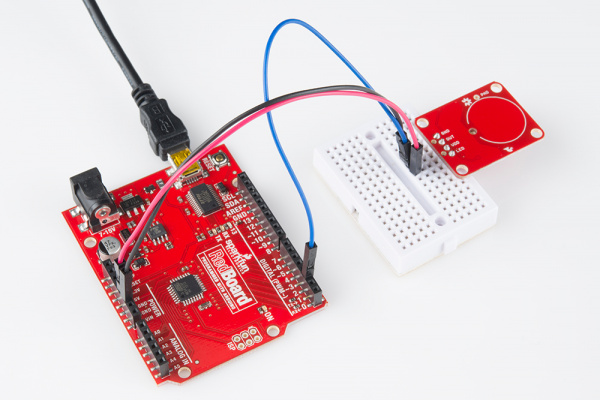
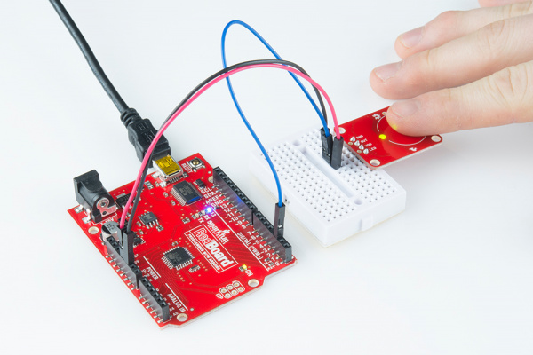
For an Arduino, make the following connections with jumper wires:
| AT42QT101X | Arduino |
|---|---|
| VDD | 5V |
| OUT | 2 |
| GND | GND |
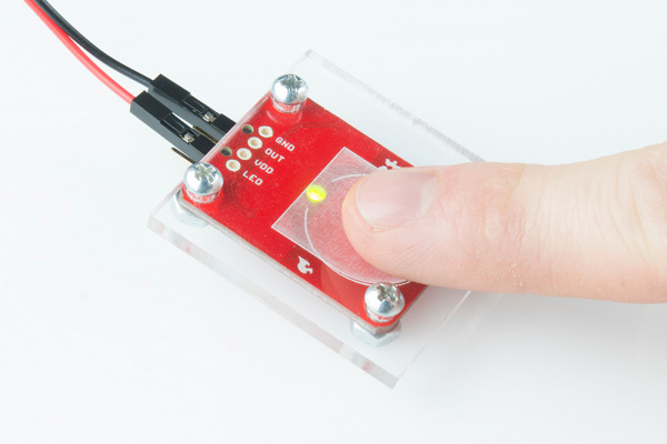
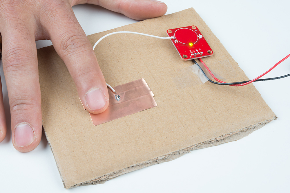
One advantage of capacitive touch boards is their ability to be mounted to panels and detect touch through thin plastic, cardboard, etc. Using a drill or laser cutter, cut four 0.125 inch holes in the same pattern as the mounting holes on the breakout board.
Attach the board to the panel using #4-40 screws and #4-40 nuts.
You can create your own electrode by using foil, copper tape, or any other conductive material. Cut or shape the electrode and attach a wire between the electrode and the PAD pin on the AT42QT101X breakout board. For a secure connection, make sure to solder the external electrode together. The electrode can be almost any shape and size.
Note: This example assumes you are using the latest version of the Arduino IDE on your desktop. If this is your first time using Arduino, please review our tutorial on installing the Arduino IDE.
Open the Arduino program and paste the following code into the sketch:
language:c
/*
 12-23-2013
 SparkFun Electronics 2013
 Shawn Hymel

 This code is public domain but you buy me a beer if you use this
 and we meet someday (Beerware license).

 Description:

 This sketch shows how to use the SparkFun AT42QT101X Breakout
 Board. If you touch the Capacitive Touch area on the breakout
 board, the LED attached to the Arduino will light up (in addition
 to the LED on the AT42QT101X breakout board).

 Simply connect power and ground to the breakout board,
 and the AT42QT101X handles all the capacitive touch functions.
 By default, the board will light up the green LED when the pad
 is touched. A wire may also be connected from OUT on the
 breakout board to a digital input pin on an Arduino. This signal
 is normally LOW but goes HIGH on a touch detection.

 The "LED Enable" solder jumper may be de-soldered in order to
 control the LED directly from the LED pin. This is useful if you
 want to light up a button that the user needs to push.

 Hardware connections:

 Uno Pin    AT42QT101X Board  Function

 +5V        VDD               Power supply
 GND        GND               Ground
 2          OUT               Capacitive touch state output
 */

// Constants
const int TOUCH_BUTTON_PIN = 2;  // Input pin for touch state
const int LED_PIN = 13;          // Pin number for LED

// Global Variables
int buttonState = 0;             // Variable for reading button

void setup() {

  // Configure button pin as input
  pinMode(TOUCH_BUTTON_PIN, INPUT);

  // Configure LED pin as output
  pinMode(LED_PIN, OUTPUT);

}

void loop() {

  // Read the state of the capacitive touch board
  buttonState = digitalRead(TOUCH_BUTTON_PIN);

  // If a touch is detected, turn on the LED
  if (buttonState == HIGH) {
    digitalWrite(LED_PIN, HIGH);
  } else {
    digitalWrite(LED_PIN, LOW);
  }
}
Plug in the Arduino and upload the code. You should see the LED on the AT42QT101X board and the LED on the Arduino light up when you touch the electrode.
Now that you've successfully got your capacitive touch breakout up and running, it's time to incorporate it into your own project!
For more information about the board, check out the resources below:
The AT42QT101X is a great way to add a single capacitive touch button to a project. Need some inspiration for your next project? Check out some of these tutorials for ideas:
You can also replace a momentary push button with a transistor and the capacitive touch sensor like the interactive 3D printed lit diamond prop project:
Or check out the following blog posts for more ideas.
learn.sparkfun.com | CC BY-SA 3.0 | SparkFun Electronics | Niwot, Colorado
