Adapting LilyPad Development Board Projects to the LilyPad ProtoSnap Plus
Introduction
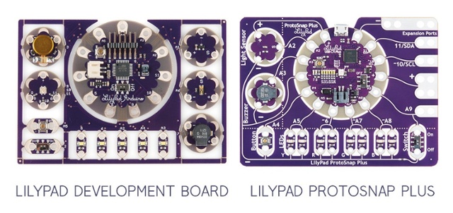
The LilyPad ProtoSnap Plus is an update and re-envisioning of the successes of the LilyPad Development Board, one of our most popular e-textile products. After many discussions with educators using the LilyPad Development Board in their programs and classrooms, our development team created a new board designed with new features and updates for improved ease of use for both students and facilitators. This guide will provide an overview of the changes made during the development of the LilyPad ProtoSnap Plus and how to adapt existing code or curriculum from the LilyPad Development for use with the ProtoSnap Plus.
New Features in the ProtoSnap Plus
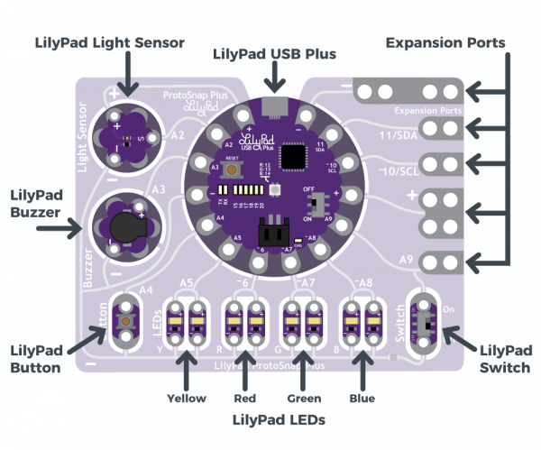
Clear, Visual Layout — The silver traces connecting LilyPad boards together to illustrate their electrical connections are a key feature of the ProtoSnap series. The new LilyPad ProtoSnap Plus includes easy-to-follow traces for students to use as a guideline for their design projects before breaking them apart and during programming lessons. In the LilyPad Development Board, many of these traces were hidden or difficult to see and point out during a lesson.
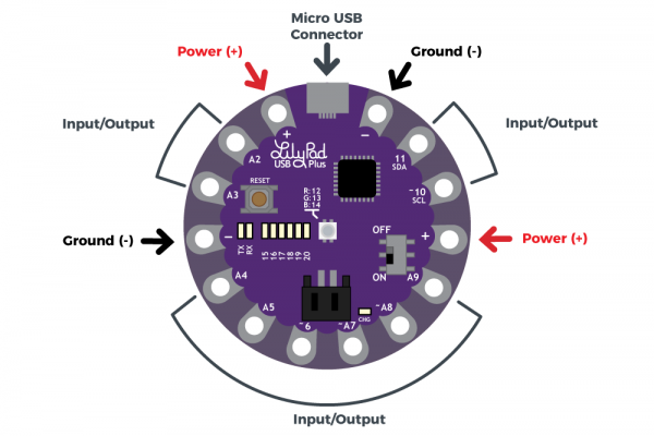
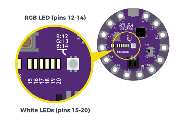
LilyPad USB Plus — Many users prefer the LilyPad USB over other formats and have been asking for an update to the Development Board to include one. SparkFun's product team created the LilyPad USB Plus with added features including a built-in RGB LED and LED bar graph, as well as two additional power (+) and ground (-) sew tabs for ease of use.
Updated Labeling — Each sew tab on the LilyPad USB Plus includes a symbol (~) at the center indicating PWM capability or analog-to-digital converter (ADC) for quick reference for users during prototyping. This eliminates the need to look at documentation or datasheets while teaching and building. These labels are also included on the bottom of the LilyPad boards. The labeling extends to board names clearly beside the hardware on the ProtoSnap board for quick identification when teaching or exploring.
More LEDs — One of the most compelling early activities when learning to program is to create blinking light patterns with Arduino. Students can create quite complex programs using just an LED and their imagination. The LilyPad ProtoSnap Plus replaces the five white LEDs and tri-color LED offered on the original LilyPad Development Board with four pairs of colored LEDs (yellow, red, blue, green), an RGB LED, and six white LEDs in a bar graph configuration. Building the RGB and white LEDs onto the LilyPad USB Plus microcontroller freed up sew tabs to connect other LilyPad boards and eliminated additional sewn connections.
Expansion Ports — To increase flexibility of the new ProtoSnap Plus, four expansion ports were added that allow students to explore different sensor and output options not available pre-wired on the board, including I2C boards.
For a full overview of the LilyPad ProtoSnap Plus and its features, check out the LilyPad ProtoSnap Plus Hookup Guide.
LilyPad ProtoSnap Plus Hookup Guide
Board Comparison Chart
Below is a table that lists the components available on each of the boards. Note that in the ProtoSnap Plus, some boards have been removed. These can easily be hooked up again using the Expansion Ports on tabs A9, 10, and 11.
| LilyPad Development Board Component | LilyPad Development Board Pin | LilyPad ProtoSnap Plus Pin | Notes |
|---|---|---|---|
| LilyPad Vibe Board (+) | 3 | N/A | The ProtoSnap Plus does not include a vibe board. |
| LilyPad Tri-Color LED | Red LED: 9 Green LED: 11 Blue LED: 10 |
Red LED: 12 Green LED: 13 Blue LED: 14 |
The ProtoSnap Plus replaces a standalone tri-color LED with a built-in RGB LED on the LilyPad USB at the center of the board.
|
| LilyPad Button | A5 | A4 | |
| LilyPad Switch | 2 | A9 | 2 is a hidden tab on the Development Board. |
| LilyPad Temperature Sensor (S) | A1 | N/A | The ProtoSnap Plus does not include temperature sensor. |
| LilyPad Light Sensor (S) | A6 | A2 | The ProtoSnap Plus uses an updated light sensor. |
| LilyPad Buzzer (+) | 7 | A3 | 7 is a hidden tab on the Development Board |
| 5 LilyPad LEDs (+) | White LED 1: 5 White LED 2: 6 White LED 3: A2 White LED 4: A4 White LED 5: A3 |
Yellow LED pair: A5 Red LED pair: 6 Green LED pair: A7 Blue LED pair: A8 |
The LilyPad ProtoSnap Plus replaces the 5 white LEDs with pairs of colored LEDs. It also includes an LED bar graph of white LEDs built into the LilyPad USB Plus on pins 15-20. |
Adapting and Uploading Code to the ProtoSnap Plus
Code written for the LilyPad Development Board can be adapted for use with the ProtoSnap Plus with a few simple changes.
First, identify if the parts are pre-wired and included on the LilyPad ProtoSnap Plus using the Board Comparison Chart. Simply update the pin number assigned in your Development Board code to the coordinating connection on the ProtoSnap Plus.
LilyPad Vibe Board
Connect the positive (+) tab of the LilyPad Vibe Board to one of the Expansion Ports and reassign the pin number in your code. We recommend using Expansion Port 10 if you wish to use PWM with the vibe board.
LilyPad Tri-Color LED
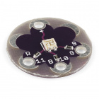
The LilyPad USB Plus at the center of the ProtoSnap Plus has a built-in RGB LED that can be used in place of the LilyPad Tri-Color LED. Note that the Tri-Color LED included on the LilyPad Development Board was a common anode while the RGB on the USB Plus is a common cathode, so your code may have to be adapted slightly to function the same.
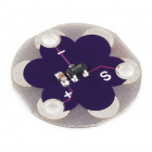
LilyPad Tri-Color LED
DEV-08467Note on Common Anode vs Common Cathode
The color channels on the Tri-Color LED LED are all connected through a common anode (positive) pin. Unlike some other RGB LEDs, this configuration means that to light up the LED you need to ground the individual red, green, and blue LEDs instead of sending them power. For simple circuit hookups, this means you need to connect the R, G, or B sew tabs to ground (-) and set them to LOW (for digital output) or 0 (for analog output) in your code to turn them on.
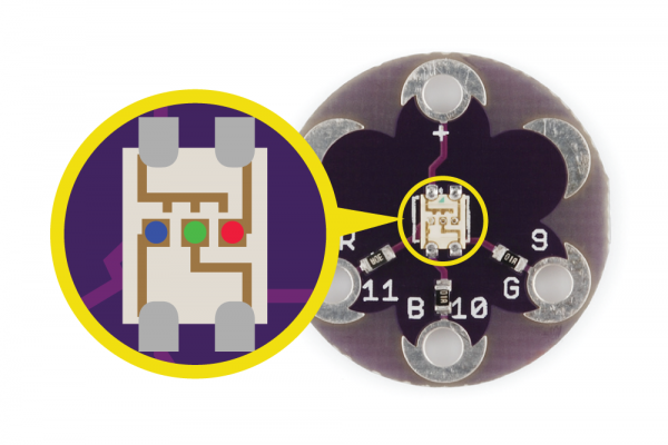
External Tri-Color LED
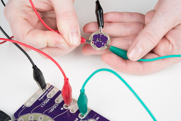
You may also connect a Tri-Color LED to the three Expansion Ports. Only Expansion Port 10 has PWM functionality, so fading the LEDs can only happen on one of the RGB channels in this hookup method.
LilyPad Temperature Sensor
Connect the S tab of an external LilyPad Temperature Sensor to Expansion Port A9 and reassign the pin number associated with the temperature sensor in your code to A9.
Uploading Code
Note that whereas the LilyPad Development Board required an FTDI breakout board to upload code, the LilyPad ProtoSnap Plus board can be programmed via the microUSB connector.
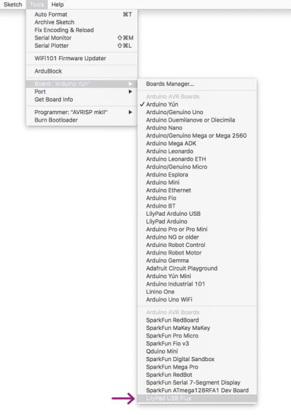
Before uploading your code to the ProtoSnap Plus, you will need to select a new board from the Board menu. The LilyPad Development Board uses a LilyPad Arduino while the LilyPad ProtoSnap Board uses a LilyPad USB Plus. If you keep LilyPad Arduino selected, it will display an error upon upload. Refer to the LilyPad ProtoSnap Plus Hookup Guide for full instructions on how to add support for the board and upload code to the USB Plus.
LilyPad Development Board: LilyPad Arduino
LilyPad ProtoSnap Plus: LilyPad USB Plus
Resources and Going Further
For more information related to LilyPads, check out the resources below:
