MESA National Challenge
SparkFun is proud to announce a great educational partnership with Mathematics, Engineering, Science, Achievement (MESA) around the MESA National Challenge. SparkFun is the hardware and professional development partner for MESA programs participating in the Prosthetic arm challenge this year. We are honored to be a part of the challenge this year and to be supporting the amazing projects coming from hundreds of students across 10 states.
MESA assists students at middle and senior high schools (and some elementary schools) so they excel in math and science and become competitively eligible for the most rigorous colleges and universities. MESA partners with teachers, administrators, school district officials and industry representatives to provide this academic enrichment model. Students are selected to participate in the MESA through a process that involves teachers at participating schools and locally-based MESA personnel.
National Challenge Overview
Each year MESA mosts a national design challenge to put students' knowledge, creativity and collaboration skills to the test. For the past couple of years this challenge has been focussed the design and construction of a functional prosthetic arm using cheap and easy to find materials. This year there is an extra layer of challenge. Students will be required to incorporate electronics and programming into their arm project using Arduino and a custom kit designed by SparkFun!
For more on the National Design Competition you can visit the MESA National competition page. If you are looking for a MESA program near you check out the state by state contact page for the nearest MESA program near you.
Handy Links

Purchase a MESA National Challenge Kit from SparkFun
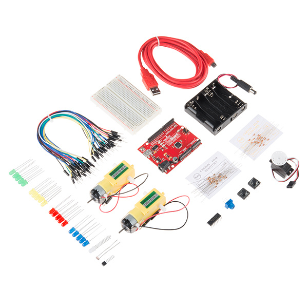
SparkFun Tinker Kit
KIT-13930Helpful Materials to Have Around
Designing and building a prosthetic arm that runs off an Arduino is quite a challenge! We have created a list of spare parts, tools and other materials to add functionality to your project. For one, we included an assortment of Hook-Up wire so that you can run any length of wire to your motors that you wish.

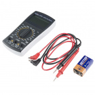
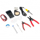
Tool Kit - Beginner
TOL-13086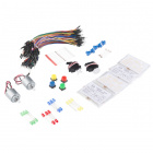
Curriculum Materials
Through years of teaching Arduino to students, educators and the public we have come up with the idea of the "Big 6". The Big 6 are the 6 major concepts that once you tackle in Arduino you can pretty much do anything you want. Below are the Big 6 and this page and the workshops associated with them are modeled around these concepts and getting you up and running with them as quickly as possible.
The Big 6
These concepts are cove throughout the circuits below. Each circuit tab has a description, wiring diagram and example code for you to reference during class or afterwards while you are extending your knowledge after we leave.
For continued support, frequently asked questions and to share with other MESA instructors please join our Google+ Community Group.
This section is to get everything installed and ready to go. This is also a great indepth introduction to the RedBoard and all of its parts, functions and how to upload code to it to do you bidding. You can also find other materials to help you install ArduBlock, the block based programming tool for Arduino as well as a few instructional materials to get you up and running.
Board Setup and Software Installation
RedBoard Hookup Guide
Instructional Materials
Giant Breadboard Poster
Arduino Cheatsheet
Collect Your Parts


Bare Minimum
Blink
LEDs are small, powerful lights that are used in many different applications. To start off, we will work on blinking an LED, the Hello World of microcontrollers. That’s right - it’s as simple as turning a light on and off. It might not seem like much, but establishing this important baseline will give you a solid foundation
Build It!

Program It!
Railroad Crossing
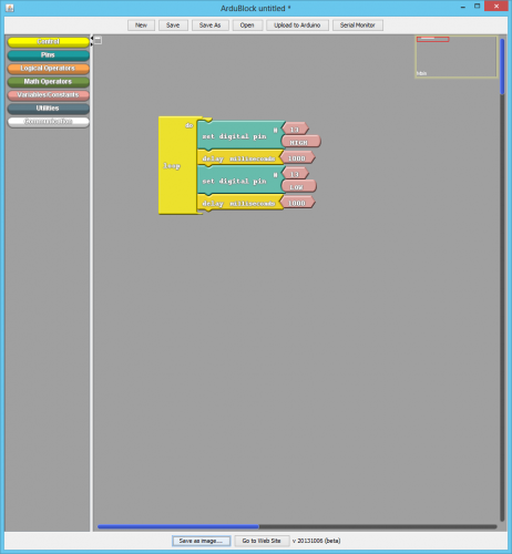
Now that you’ve gotten your LED to blink on and off, it’s time to up the stakes a little bit – by connecting two LEDs at once. We’ll also give you a first go around with a breadboard. This circuit is a great setup to start practicing writing your own programs and getting a feel for the way Arduino works.
Build It!

Program It!
Landing Lights
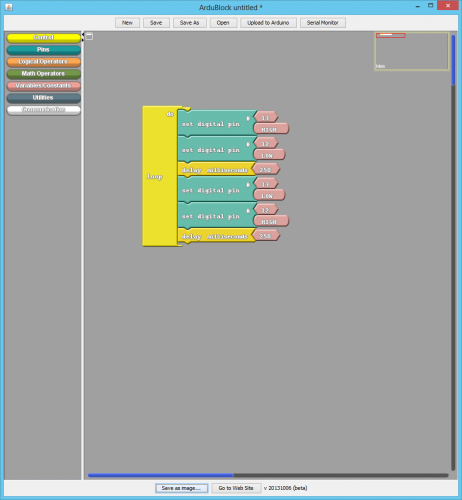
Now that you’re used to the breadboard, it’s time to up the stakes even more – by connecting four or more LEDs at once! We’ll also give your RedBoard or Arduino R3 a little test by creating various lighting sequences.
Build It!

Program It!
Collect Your Parts!

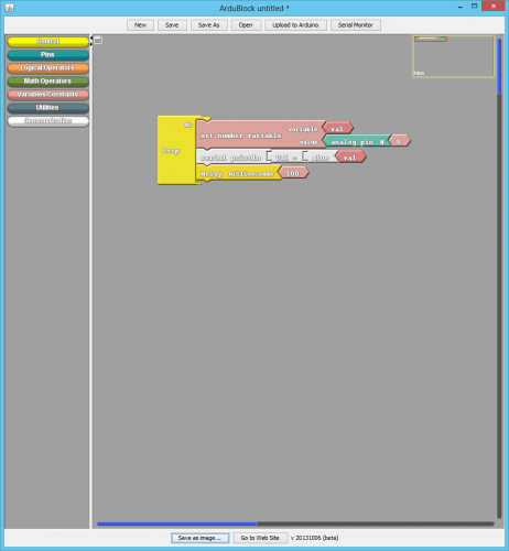
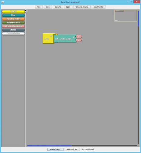
AnalogRead Print
A potentiometer is also known as a variable resistor. When powered with 5V, the middle pin outputs a voltage between 0V and 5V, depending on the position of the knob on the potentiometer. A potentiometer is a perfect demonstration of a variable voltage divider circuit. The voltage is divided proportionate to the resistance between the middle pin and the ground pin. In this circuit you will simply take that reading of voltage and print it out over your serial port so you can view it.
Build It!

Program It!
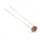
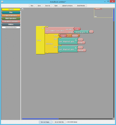
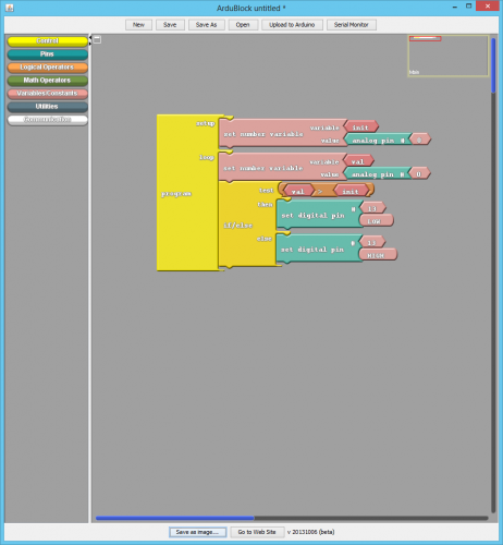
Simple Night Light
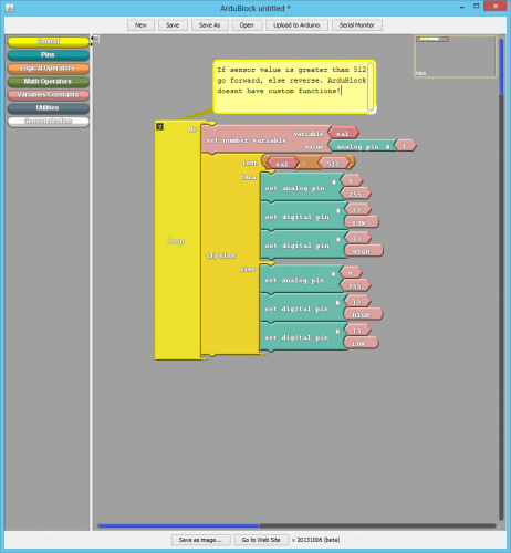
Earlier, you got to use a potentiometer, which varies resistance based on the twisting of a knob. In this circuit, you’ll be using a photoresistor, which changes resistance based on how much light the sensor receives. Since the RedBoard can’t directly interpret resistance (rather, it reads voltage), we need to use a voltage divider to use our photoresistor. This voltage divider will output a high voltage when it is getting a lot of light and a low voltage when little or no light is present.
Build It!

Program It!
Calibrated Night Light
Your night light works pretty well, but what if you want to move it to a different location and not calibrate it manually? You can do that in setup and using a calibration variable to compare your current reading against. This works for nighlights, but also any other sensor that you want to have a baseline to start with.
Build It!
Program It!
Collect Your Parts

Resistor 330 Ohm 1/6 Watt PTH - 20 pack
COM-11507
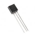
Transistor - NPN (P2N2222A)
COM-12852Simple AnalogWrite
description
Build It!

Program It!
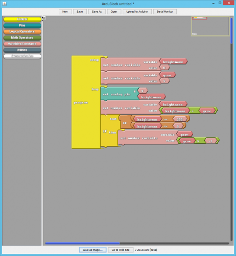
Dimmer
A potentiometer is a perfect demonstration of a variable voltage divider circuit as shown earlier. The voltage is divided proportionate to the resistance between the middle pin and the ground pin. In this circuit, you’ll learn how to use a potentiometer to control a value stored as a variable and then used to control the brightness of an LED.
Build It!

Program It!
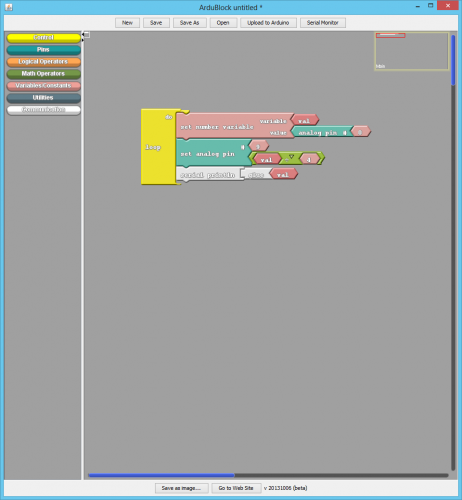
Fade with a Variable
Variables...change! Hence they are called variables. We can change them in code by using math! I know...Math; you have got to be kidding me! We can use an equation to increment or decrement a variable based on its value. This sketch increments a variable until it reaches 255 and then changes directions and decrements back to zero and start over again. This is a great use of an if statement as well as how you can manipulate numbers in code.
Build It!
Program It!
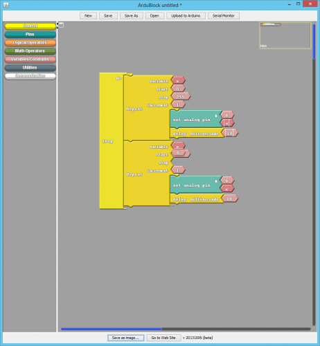
Fade with a For Loop
Fade with a variable is great, but it can be simplified. Enter the for loop! With a a for loop you define a variable and its value, its minimum or maximum range and then what to increment/ decrement by and then do something in that loop that many times. If this seems confusing, it is at first. But, I think once you look at the code it will start to be clearer.
Build It!
Program It!
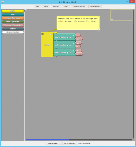
RGB LED
You know what’s even more fun than a blinking LED? Changing colors with one LED. RGB, or red-green-blue, LEDs have three different color-emitting diodes that can be combined to create all sorts of colors. In this circuit, you’ll learn how to use an RGB LED to create unique color combinations. Depending on how bright each diode is, nearly any color is possible!
Build It!

Program It!
Collect Your Parts
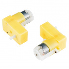
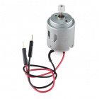
Simple H-Bridge
Now, we are going to tackle spinning a motor. This requires the use of an H-Bridge, which can switch a larger amount of current than the RedBoard cannot do. But, wait there is more! An H-Bridge can also be used to change the direction of the current that it switches (direction of the motor spinning) and the motor speed. Did anyone say "Robots"?
Build It!

Program It!

H-Bridge and Custom Motor Functions
The H-Bridge is awesome! You can control 2 seperate motors using only a few pins. But, more pins usually means more coding, and every time you want to change the direction you have to write a couple lines of code. There is help with that: custom functions! You can create your own functions and define them only once to use later.
Build It!
Program It!
Buttons and Functions
Earlier, we used an analog input to read the potentiometer. In this circuit, we’ll be reading in one of the most common and simple inputs – a push button – by using a digital input. The way a push button works with your RedBoard is that when the button is pushed, the voltage goes LOW. You RedBoard reads this and reacts accordingly.
Build It!

Program It!
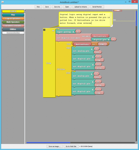
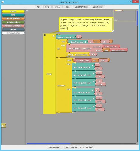
Latching Button with H-Bridge
What? You don't want to constantly hold your button down for something to happen? Enter the idea of latching! Latching is the idea of pressing a button and it staying on until you press it again and the other way around. There are latching buttons out there, but we will look at how to accomplish latching in software rather than go find latching buttons.
Build It!
Program It!
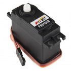
Collect Your Parts

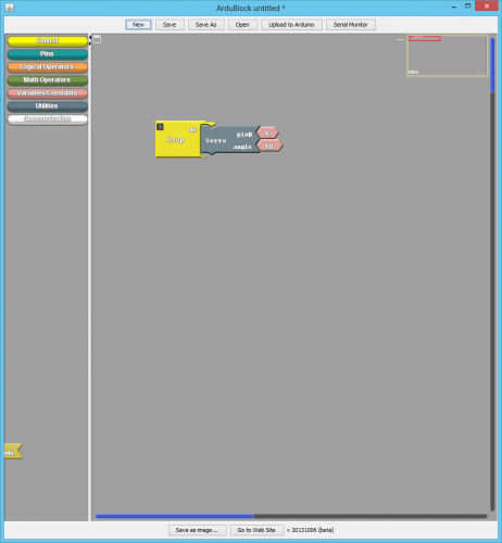
Simple Servo Write
Servos are ideal for embedded electronics applications because they do one thing very well that motors cannot – they can move to a position accurately. By varying the pulse width of the output voltage to a servo, you can move a servo to a specific position. For example, a pulse of 1.5 milliseconds will move the servo 90 degrees. In this circuit, you’ll learn how to use PWM (pulse width modulation) to control and rotate a servo.
Build It!

Program It!
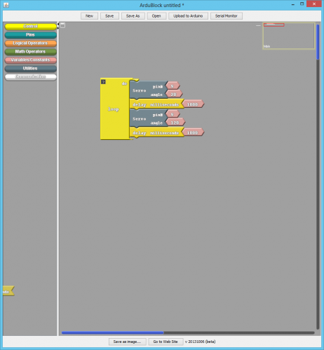
Servo "Blink"
Earlier you wrote a single angle to a servo. Well, thats kinda boring. You can write multiple angles in your loop to animate a servo to control a robotic arm, a small door, or even the fuel gauge on a car. This sketch mashes up the good old blink sketch and a servo to get a servo to move back and forth.
Build It!
Program It!
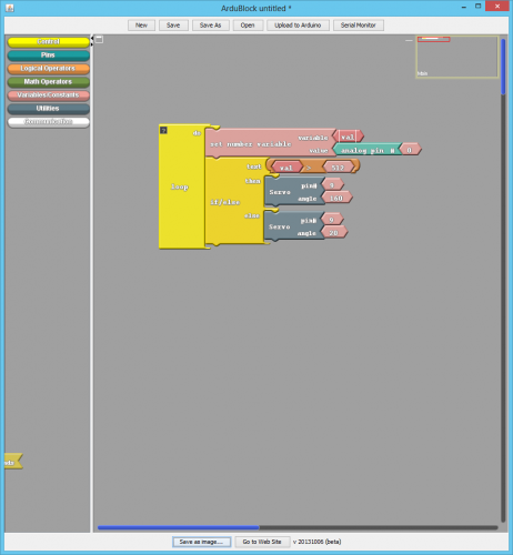
Servo "Night Light"
Do you remember your night light sketch. It turned on an LED, which is great. But, you want to have your chicken coupe door open in the morning when the sun comes up and close in the evening when the sun goes down. You can do this with a mash up of the Night Light code and the Servo.
Build It!

Program It!
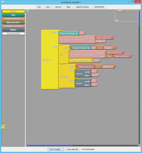
Button Latching with a Servo
You can apply the concept of latching to a servo and a number of angles depending the latching variable. Instead of a single 1 or 0, you are going to store numbers from 0 to 4, each one will have an angle associated with it. To control your servo you will be using "else if" to further expand an if statement to multiple options.
Build It!

Program It!
Soldering Resources
Microcontrollers for Educators Materials
Of particular interest: