How to Use a Multimeter
This Tutorial is Retired!
This tutorial covers concepts or technologies that are no longer current. It's still here for you to read and enjoy, but may not be as useful as our newest tutorials.
 Nate
Nate 
Changing the Fuse
One of the most common mistakes with a new multimeter is to measure current on a bread board by probing from VCC to GND (bad!). This will immediately short power to ground through the multimeter causing the bread board power supply to brown out. As the current rushes through the multimeter, the internal fuse will heat up and then burn out as 200mA flows through it. It will happen in a split second and without any real audible or physical indication that something is wrong.
Wow, that was neat. Now what? Well first, remember that measuring current is done in series (interrupt the VCC line to the breadboard or microcontroller to measure current). If you try to measure the current with a blown fuse, you'll probably notice that the meter reads '0.00' and that the system doesn't turn on like it should when you attach the multimeter. This is because the internal fuse is broken and acts as a broken wire or open. Don't worry, this happens all the time, and it costs about $1 to fix.
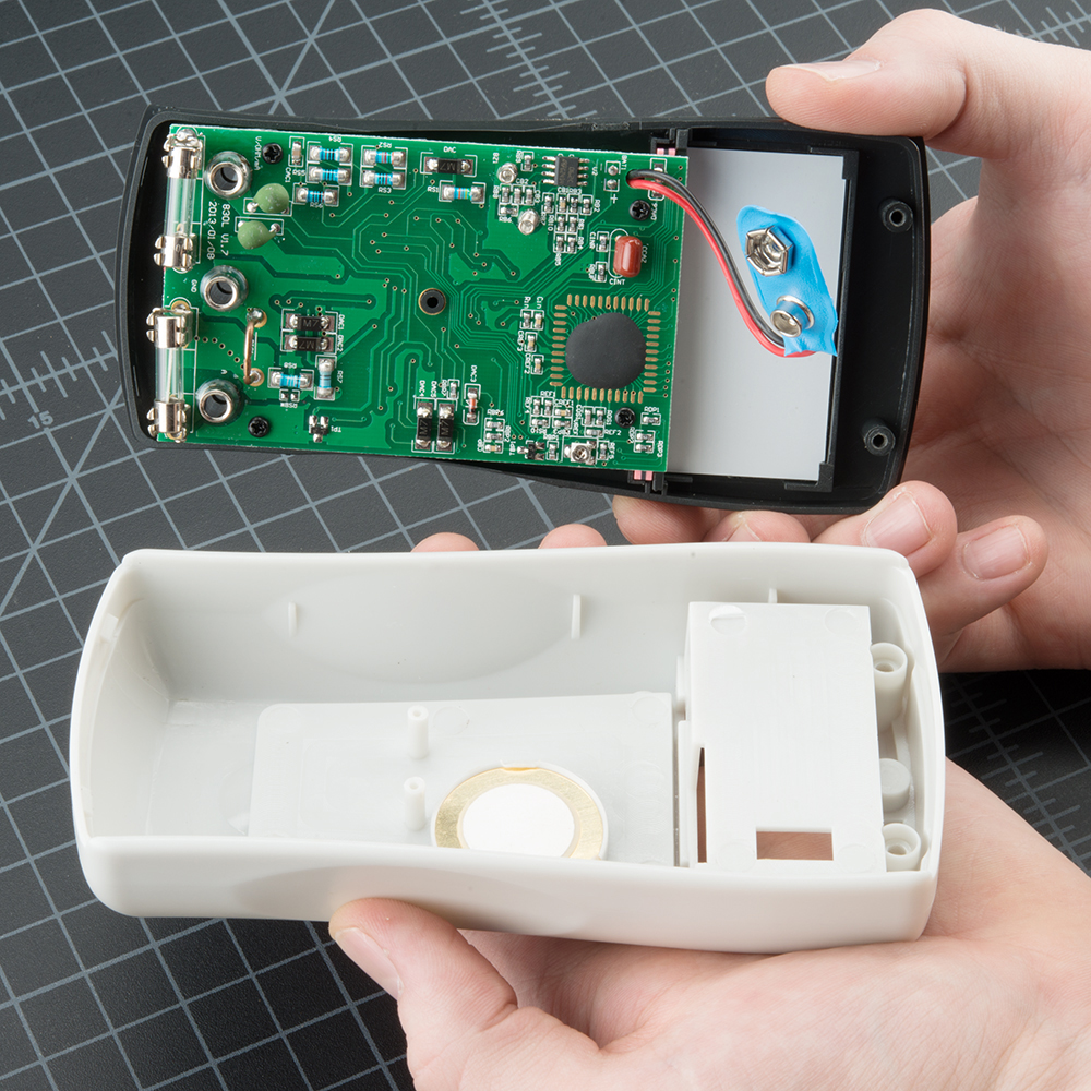
To change the fuse, find your handy dandy mini screw driver, and start taking out screws. The SparkFun DMM is pretty easy to pull apart. Start by removing the battery plate and the battery.
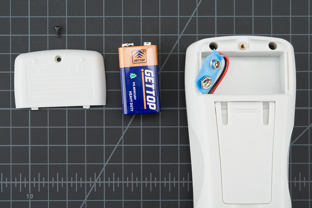
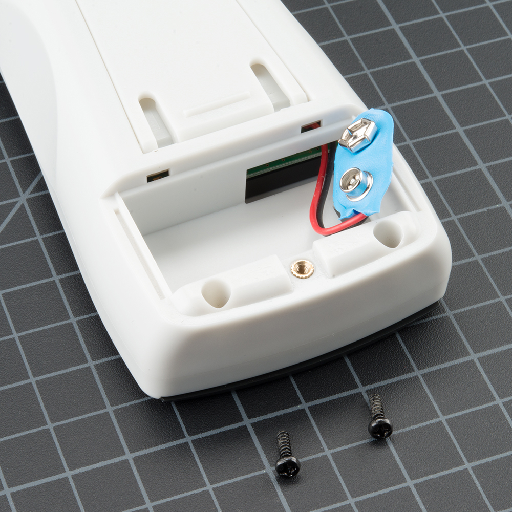
Next, remove the two screws hiding behind the battery plate.
Lift the face of the multimeter slightly.
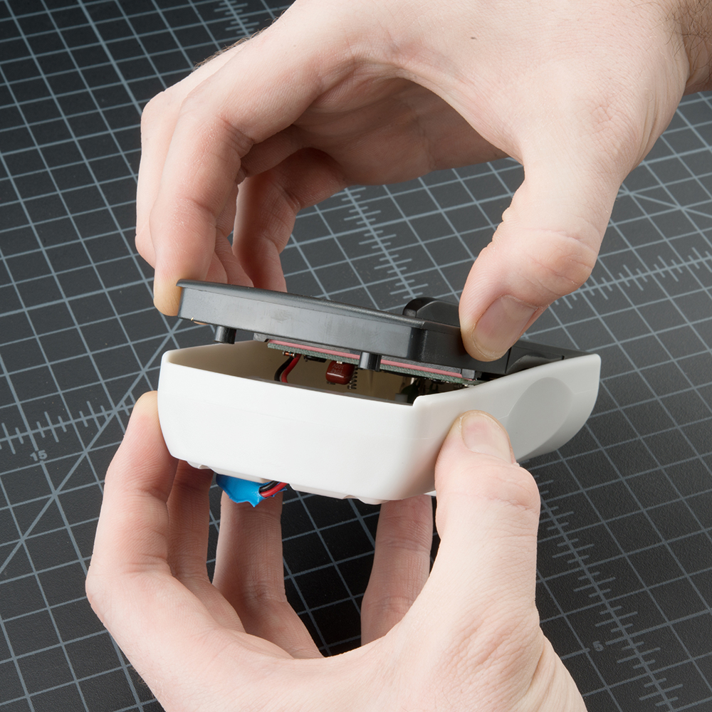
Now notice the hooks on the bottom edge of the face. You will need to slide the face sideways with a little force to disengage these hooks.
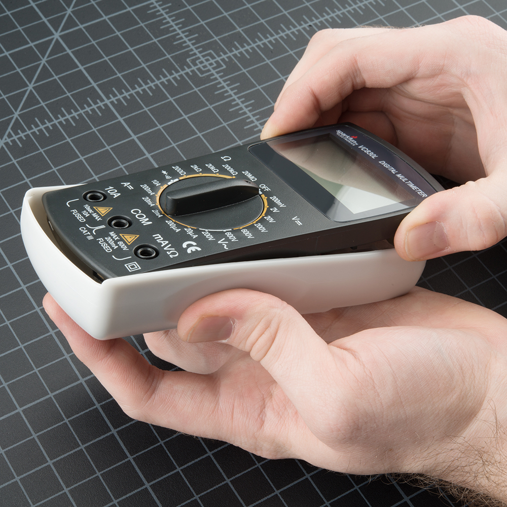
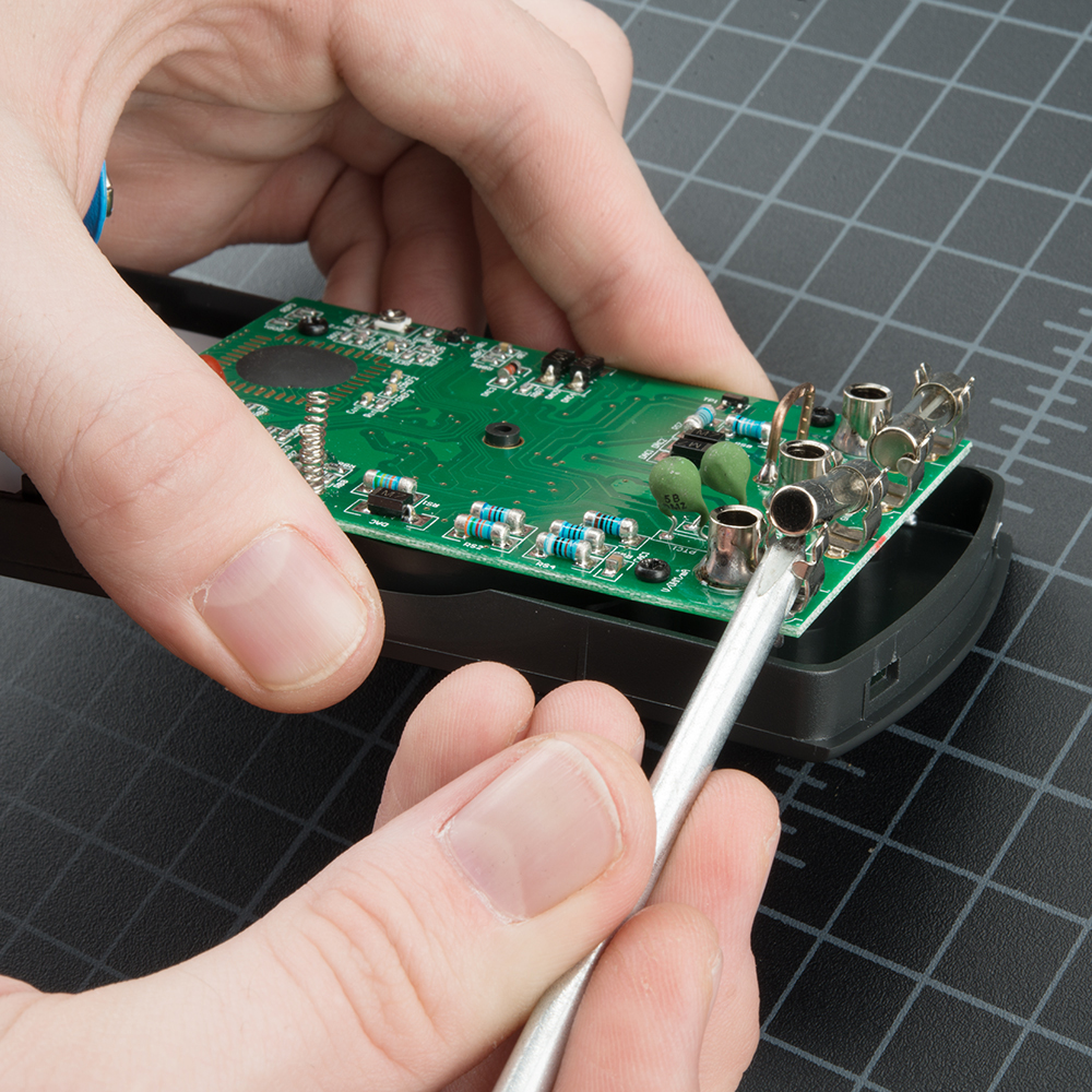
Once the face is unhooked, it should come out easily. Now you can see inside the multimeter!
Gently lift up on the fuse, and it will pop out.
Make sure to replace the correct fuse with the correct type. In other words, replace the 200mA fuse with a 200mA fuse.
The components and PCB traces inside the multimeter are designed to take different amounts of current. You will damage and possibly ruin your multimeter if you accidentally push 5A through the 200mA port.
There are times where you need to measure high current devices like a motor or heating element. Do you see the two places to put the red probe on the front of the multimeter? 10A on the left and mAVΩ on the right? If you try to measure more than 200mA on the mAVΩ port you run the risk of blowing the fuse. But if you use the 10A port to measure current, you run a much lower risk of blowing the fuse. The trade-off is sensitivity. As we talked about above, by using the 10A port and knob setting, you will only be able to read down to 0.01A or 10mA. Most of my systems use more than 10mA so the 10A setting and port works well enough. If you're trying to measure very low power (micro or nano amps) the 200mA port with the 2mA, 200uA, or 20uA could be what you need.
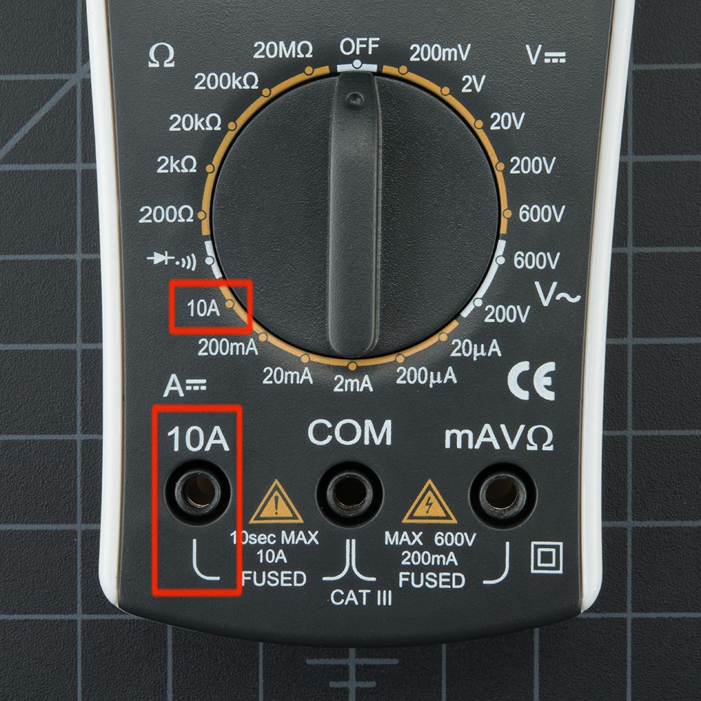
Remember: If your system has the potential to use more than 100mA you should start with the red probe plugged into the 10A port and 10A knob setting.
With sub $50 digital multimeters, the measurements you are likely to take are just trouble shooting readings, not scientific experimental results. If you really need to see how the IC uses current or voltage over time, use an Agilent or other high quality bench unit. These units have higher precision and offer a wide range of fancy functions (some include Tetris!). Bunnie Huang, hardware designer behind Chumby, uses high-precision current readings to trouble shoot boards during the final testing procedures of a Chumby. By looking at the current consumption of different boards that have failed (for example a given failed board uses 210mA over the normal), he could identify what was wrong with the board (when the RAM fails, it generally uses 210mA over normal). By pinpointing what may be potentially wrong, the rework and repair of boards is made much easier.