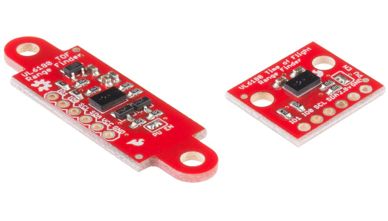
The VL6180 is a Time of Flight (TOF) distance sensor with an I2C ("Wire") interface. This Hookup Guide will cover two boards. The VL6180 Breakout and the VL6180 Sensor. These boards are very similar in function though the VL6180 Sensor has additional hardware for level shifting and voltage regulation.
Many distance sensors rely on reflected light intensity or reflected angles to determine range. This sensor uses a precise clock to measure the time it takes light to bounce back from a surface. This is a great benefit over other methods because it can be much more accurate and more immune to noise. This sensor is commonly found in cellphones as the sensor that detects when the caller is holding their phone to their ear.
We will show you how to connect this sensor to an Arduino microcontroller and use the included software library to get measurements out of the sensor. (If you're using a different type of microcomputer these instructions and source code may still help.)
This part is easy to use. But before you start, we recommend the following background knowledge:
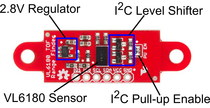
The VL6180 Breakout is as simple as it gets. Only the required passives are populated to give users the smallest, most cost effective way to use multiple sensors in a project.
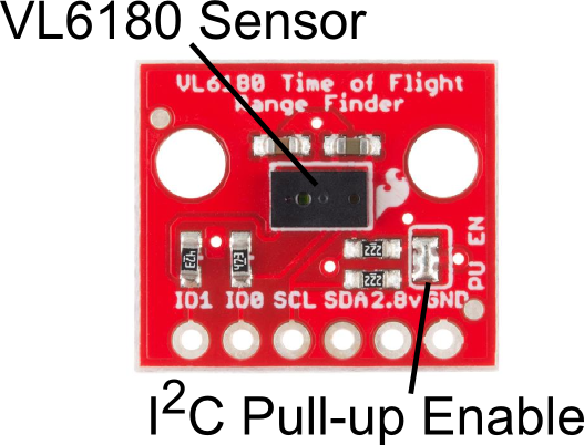
NOTE: This device only accepts 2.8V input and logic. You must provide a 2.8V voltage source and level shifting to 3.3V and 5V devices.
The VL6180 Sensor is very similar to the VL6180 Breakout with some noted additions.
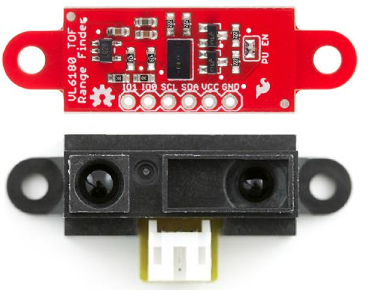
Another thing to note is the form factor of the sensor itself. Many small robotics platforms have integrated hole patterns for the long time favorite Sharp IR sensor line. This allows the VL6180 Sensor to be a near drop-in replacement for most Sharp sensors.
To use the VL6180 Breakout, follow the diagram below. One important thing to note is you MUST use a 3.3v Pro-Mini for this to work. We are cheating the 2.8v Level shifting rules in this hookup. Since I2C is an active low signal, we will use the pull-up resistors on the breakout to provide our logic voltage. We have a great I2C tutorial that explains this in more detail. To provide the required 2.8V we are using an LM317 regulator. The output voltage is tuned to 2.8V with the two resistors shown.
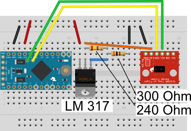
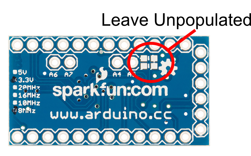
NOTE: To use this diagram make sure the two pull-up resistors on the Pro-Mini are NOT populated.
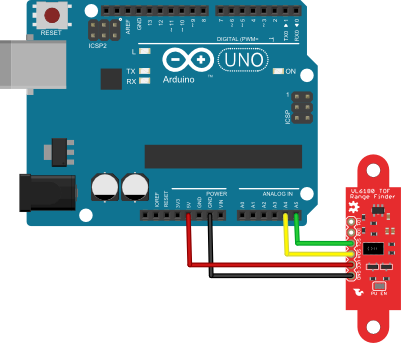
To use the Sensor version of the VL6180, things are much simpler. The board carries its own level shifting and regulation. The VL6180 Sensor can work with 3.3-5V Logic and power.
To use either the VL6180 Sensor or Breakout, you will need some supporting software. If you are using an Arduino, then you are in luck! We created an Arduino library that makes the VL6180 easy to use. Click the button below to download the latest version of the VL6180 Library.
Unzip the downloaded file and navigate to \

Follow this guide on installing Arduino libraries to install the files within the SFE_VL6180x directory as an Arduino library.
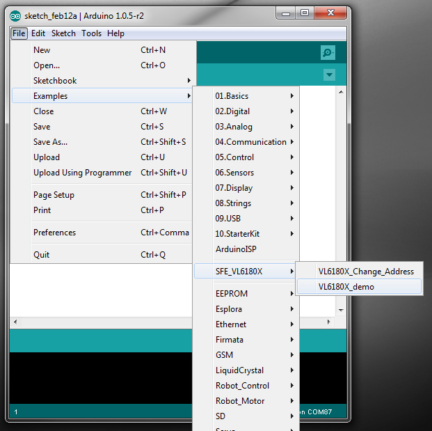
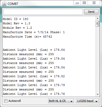
There is a sample sketch associated with the Library. VL6180X_demo reads the distance and light outputs and reports them to the screen.
Now that we have covered some of the basic features of the VL6180 Sensor and Breakout, check out some of these other tutorials and helpful links.
Or check out this blog post for ideas:
learn.sparkfun.com | CC BY-SA 3.0 | SparkFun Electronics | Niwot, Colorado