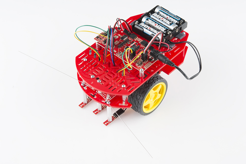
The RedBot is robotic development platform capable of teaching basic robotics and sensor integration! Based on the SparkFun RedBoard and programmable in the Arduino environment, the RedBot has all the I/O you need to make a small robot in no time at all.
When you purchase the RedBot Kit, you should have the following materials:
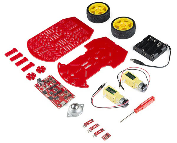
Along with everything listed above, you will also need 4x AA batteries to power your RedBot.
This tutorial will cover how to install all the parts you received with your RedBot Kit, PLUS it will go over how to install a few extra parts NOT included with the kit. These parts include the Wheel Encoder Kit, RedBot Buzzer, and two RedBot Mechanical Bumpers.
Again, you do not need these parts to assemble your RedBot, but they will be present throughout this guide. Please ignore any instances of the extra sensors if you do not need to assemble them. Sections pertaining strictly to these extra parts will be marked with **asterisks**.
If you are installing one or all of these extras, you may also want to get a few more jumper wires.
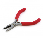
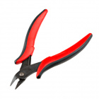
A needle nose pliers, Flush Cutters and a screwdriver are also useful when putting together the RedBot.
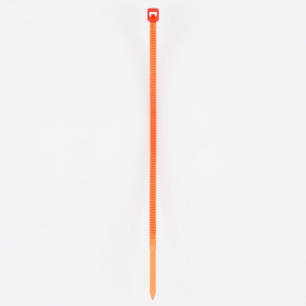
If you are following this tutorial and using the Wheel Encoder Kit, you will want 2x 4" zip-ties to connect the wheel encoder to the motors included in the RedBot kit.
To better understand the RedBot and all of its parts, we recommend checking out the Getting Started with the RedBot tutorial.
Read on if you are using the Wheel Encoder Kit. If not, skip to the next section.
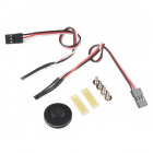
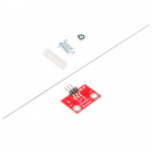
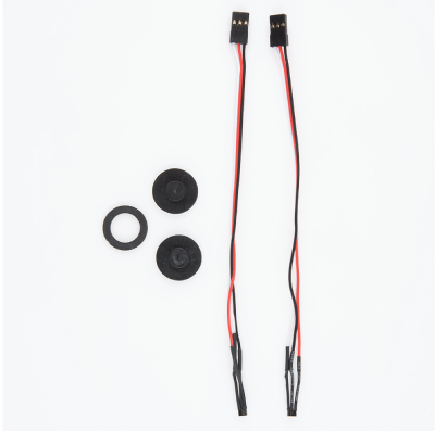
The Wheel Encoder Kit is a simple add-on to any wheeled robot that can help measure the speed or distance the chassis travels. For the RedBot, we found that it is easier to use this wheel encoder.
| 2x Motor | 2x 4" Zip-Tie | 1x Wheel Encoder Kit |
 |
 |
 |
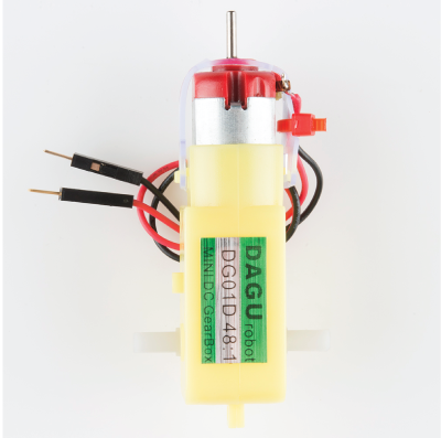
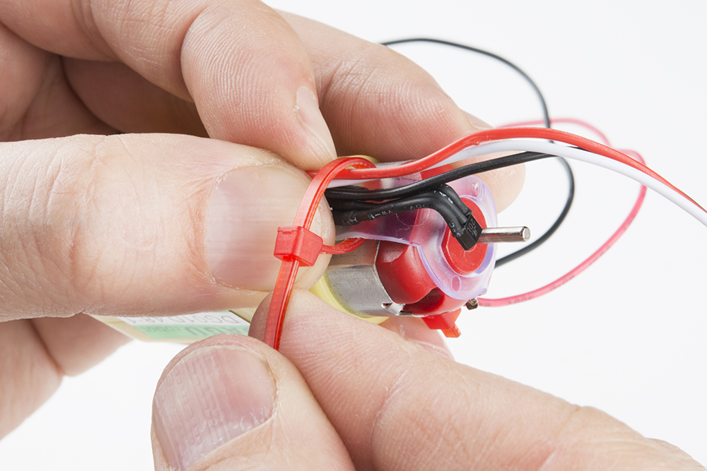
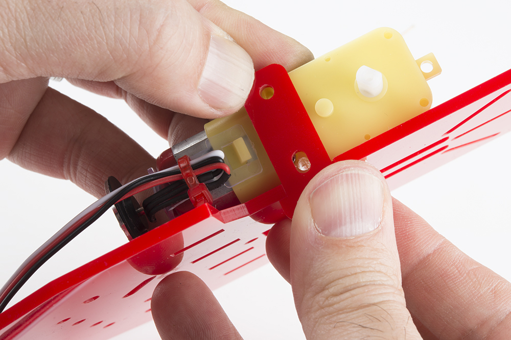
First, you will want to grab a 4" zip-tie (a smaller zip-tie will work as well). Push the zip-ties inside the opening between the clear plastic and the motor. Make sure the zip-tie is going through the opening that isn't on the same side as the black and red wires soldered to the motor.
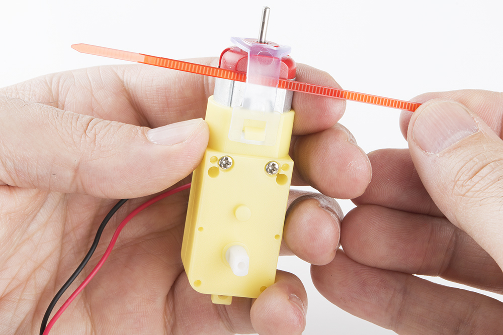
Next, slightly close the zip-tie. Make sure not to fully tighten the zip-tie yet.
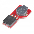
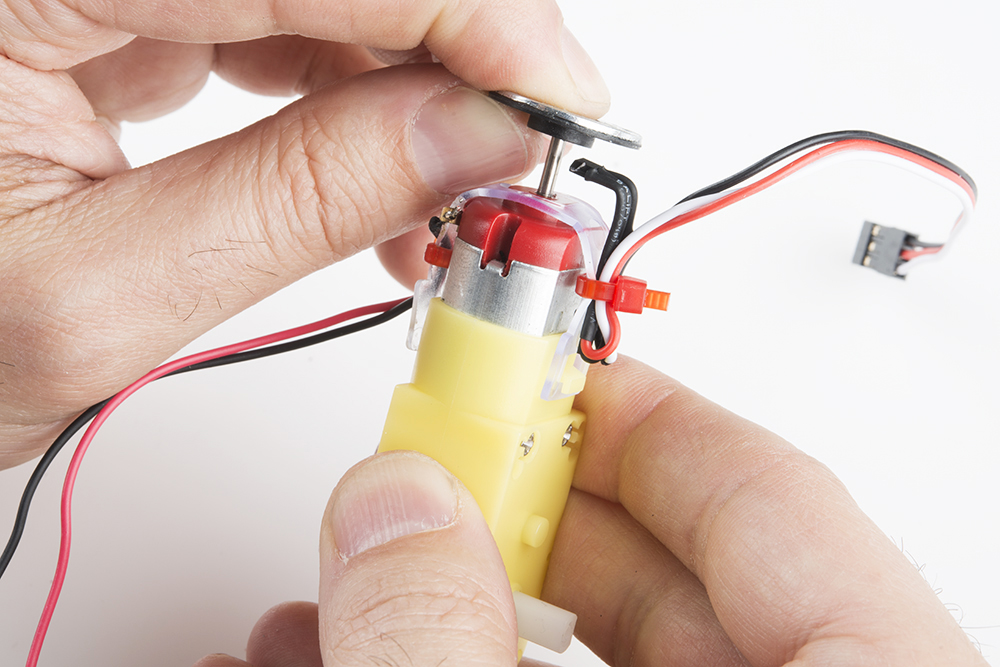
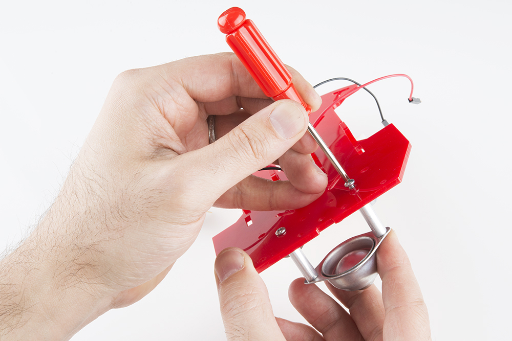
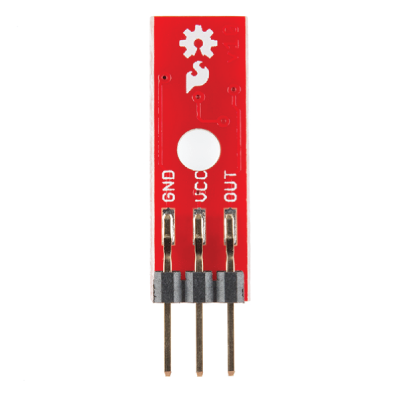
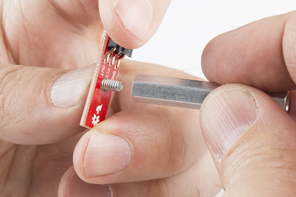
Grab the hall effect sensors, terminated with 150mm cables and a 3-pin female servo header, from the Wheel Encoder Kit. Bend the hall effect sensor side downward at a 90 degree angle, as shown in the photo below.
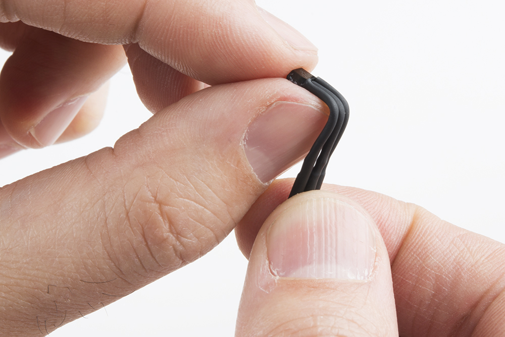
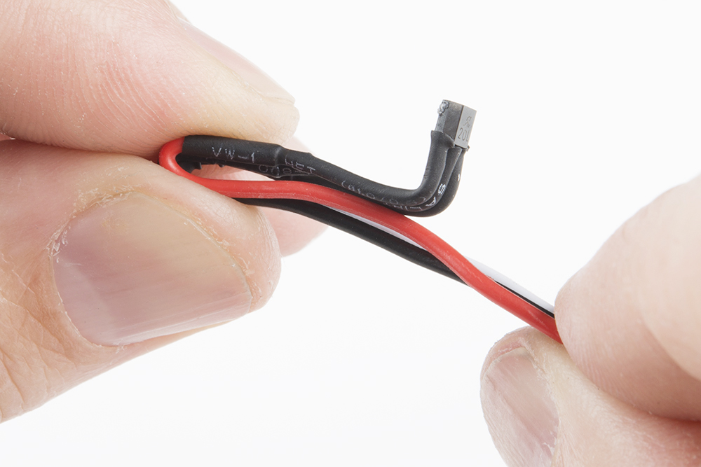
Bend the hall effect sensors cable again, so it is laying horizontal on itself. Bending the cable again makes this setup sturdier and the hall effect sensor less likely to move around.
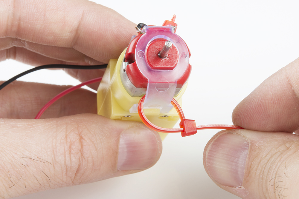
Place the bent hall effect sensors cable through the zip-tie loop created earlier. You will want to line up and point the hall effect sensor to the middle of the shaft of motor.
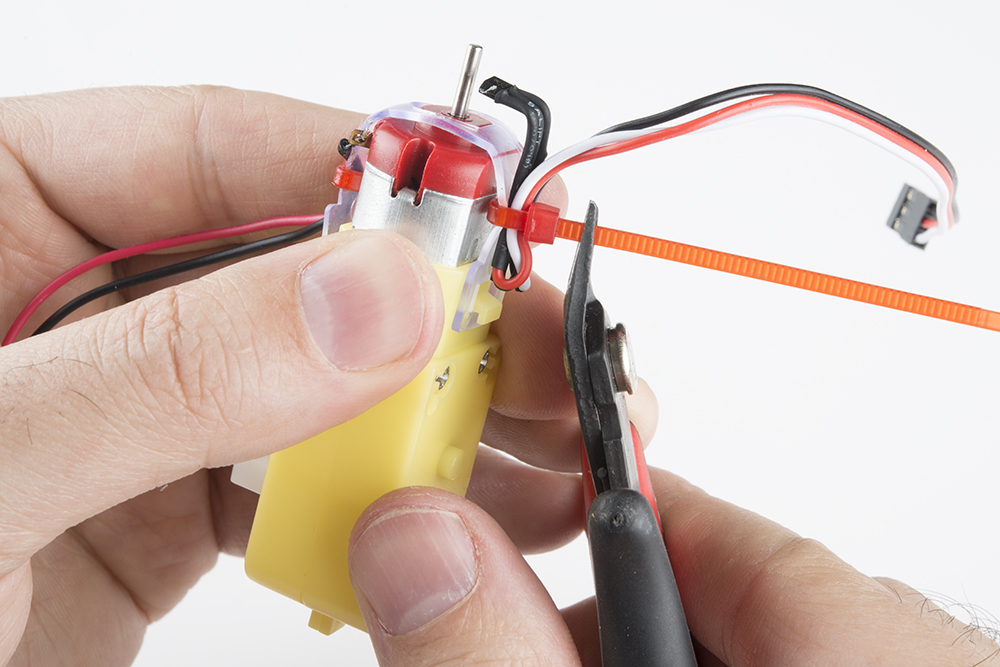
Tighten the zip-tie firmly. Make sure the hall effect sensor is still pointing inward to the shaft of the motor. Using flush cutters, cut the zip-tie's extra end hanging out.
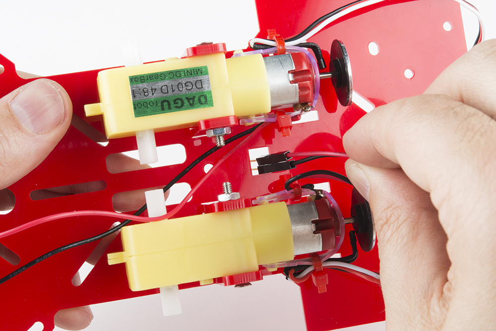
Add the neodymium 8-pole magnet with the rubber hub to the shaft of motor. The hall effect sensor should be horizontal.
Go ahead and do the same the wheel encoder setup to the other motor.
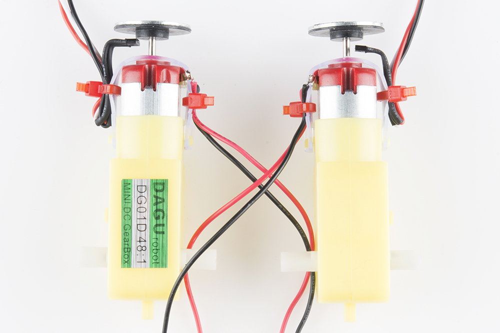
Double check the hall effect sensors are nice and lined up between the motor and magnet with the rubber hub. Also be sure that it is pointed inward toward the shaft of the motor.
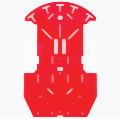
In this section, you will be placing the two motors on the bottom side of the bottom chassis piece.
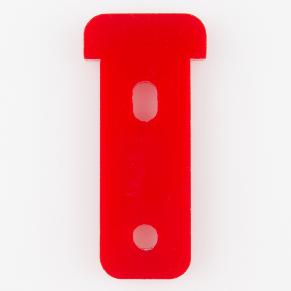
| 1x Bottom Chassis Piece | 4x Motor Holder | 2x Motor |
 |
 |
|
| 2x 4-40 x 1 1/4" Flat Head Screw | 2x 4-40 Hex Nut | |
 |
 |
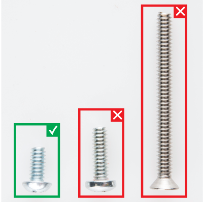
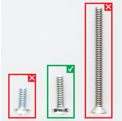
Please note: ** Pay close attention to which screws you are using. There are two different screws in the RedBot Kit. (30x** of the 4-40 x 1/4" Phillips screw and 4x of the 4-40 x 1 1/4" flat head screw).
Adding the RedBot Sensor - Mechanical Bumper? You will have 3x of the 4-40 x ⅜" Phillips screw.
Find the correct location on the bottom chassis piece.
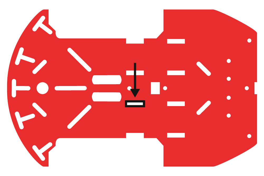
Place one of the motor holders through the chassis at that location.
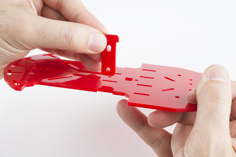
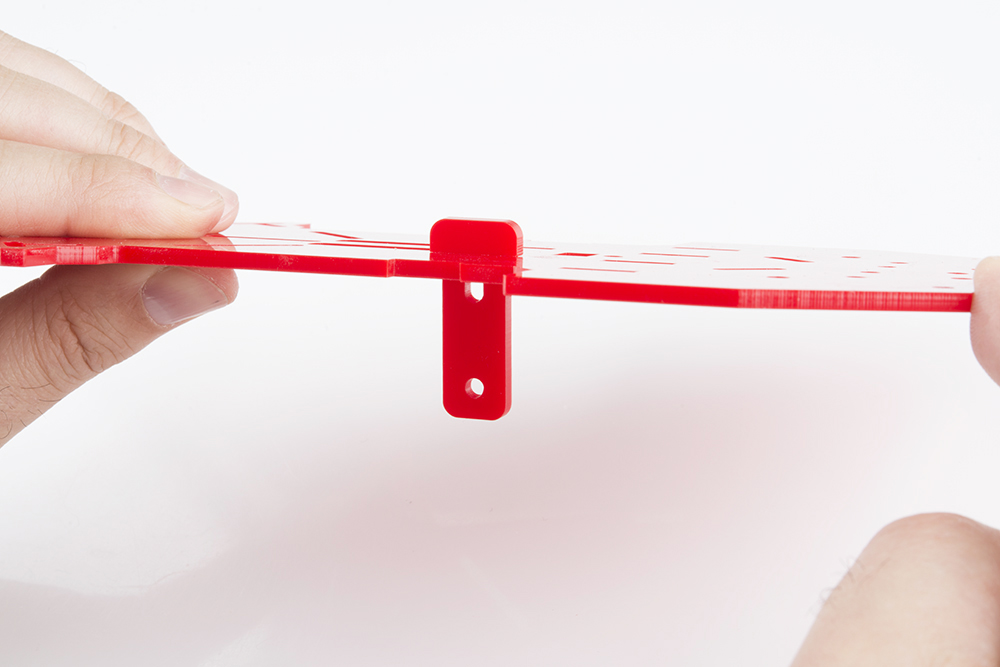
Push the motor holder all the way down.
Place the first motor on the bottom side of the chassis piece. It is important to make sure the side of the motor with the wheel encoder is pointing to the back side of the RedBot bottom chassis piece. To tell the difference between the back and front of the chassis, the chassis's back is flat and the chassis's front is curved. (The back of the chassis is where the metal ball caster will go. You will be putting that on later.)
Line up the two motor holes with the two motor holder holes. Make sure that the red wire soldered onto the motor is on top and away from the chassis piece.
Place the 4-40 x 1 1/4" flat head screw through the top motor holder and motor holes.
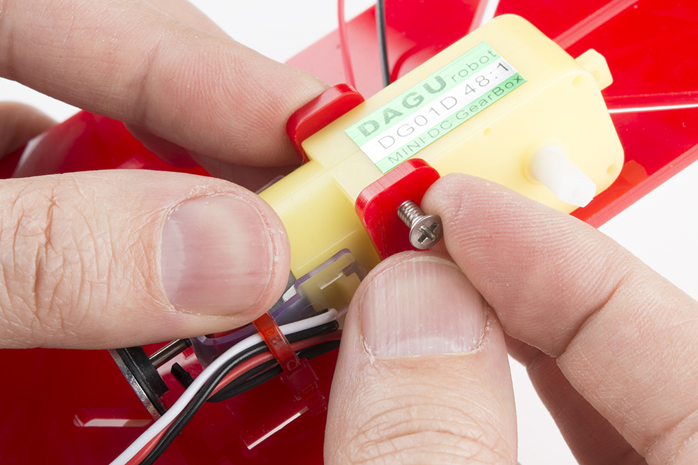
Using a screwdriver and 4-40 hex nut, tighten the screw.
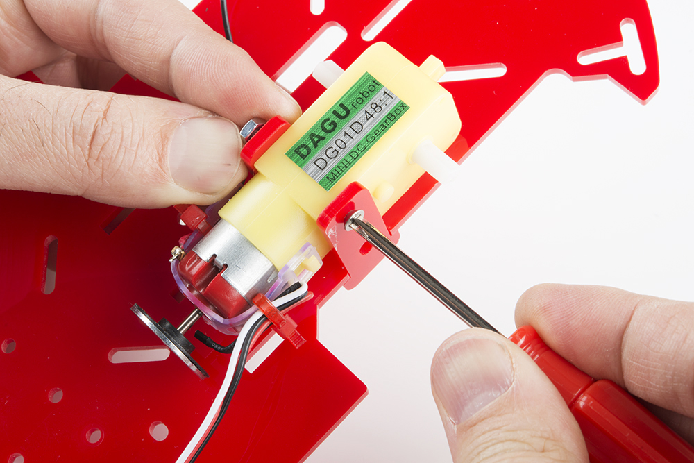
Double check the side of the motor with the wheel encoder is pointing to the back side of the RedBot bottom chassis piece.
Following the same steps as the first motor, add the second motor holder on the other side.
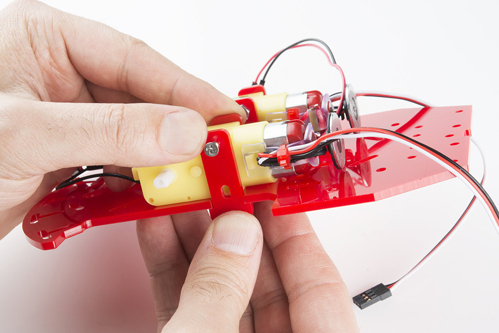
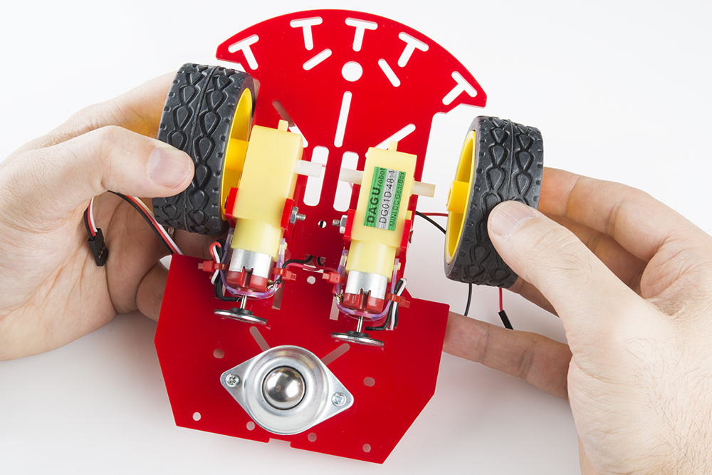
Place the motor's black and red wires through the bottom chassis so the wires come through to the top side of the chassis.
Now, push the wheel encoder's wires through to the top side of the chassis. It is best to push through the chassis opening that is closest to the motor, as shown below.

As you can see, the wires are now through the top of the chassis piece. It is highly recommended to have the wires push through the same chassis openings as shown below. This way it is easier to connect to the RedBot Mainboard toward the end.
In this section, you will be adding the metal ball caster to the bottom side of your bottom chassis piece.
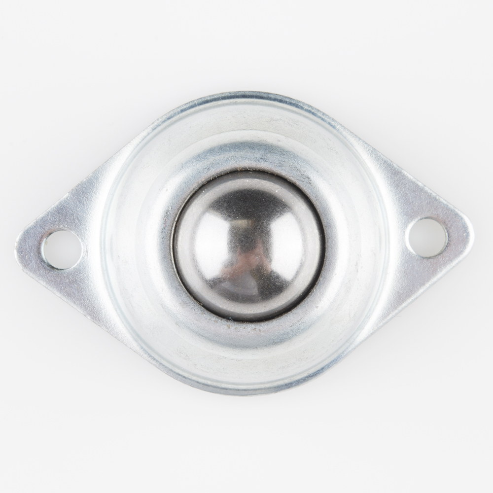
| 4x 4-40 x 1/4" Phillips Screw | 1x Metal Ball Caster | 2x 4-40 x 1" Metal Standoff |
 |
 |
 |
Please note: ** Pay close attention to which screws you are using. There are two different screws in the RedBot Kit. (30x** of the 4-40 x 1/4" Phillips screws and 4x of the 4-40 x 1 1/4" flat head screws).
Adding the RedBot Sensor - Mechanical Bumper? You will have 3x of the 4-40 x ⅜" Phillips screws.
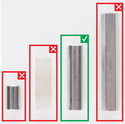
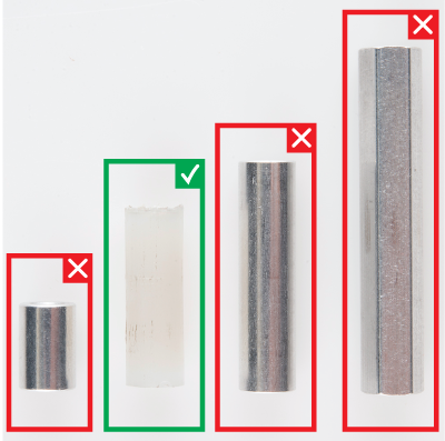
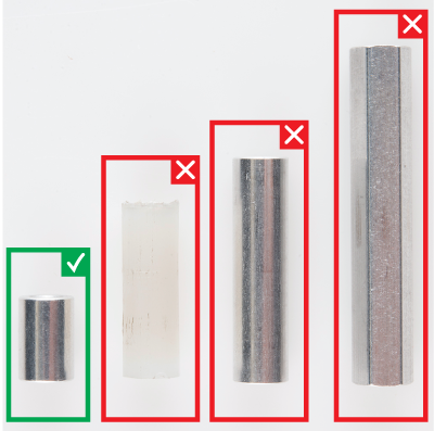
There are also different standoffs in the RedBot Kit and add-ons. The RedBot Kit comes with 7x 4-40 x 1" metal standoffs, 4x 4-40 x ⅜" metal standoffs, and 3x 4-40 x 1 1/2" metal hex standoffs.
Adding the RedBot Sensor - Mechanical Bumper? You will have 3x of the 4-40 x 3/4" nylon standoffs.
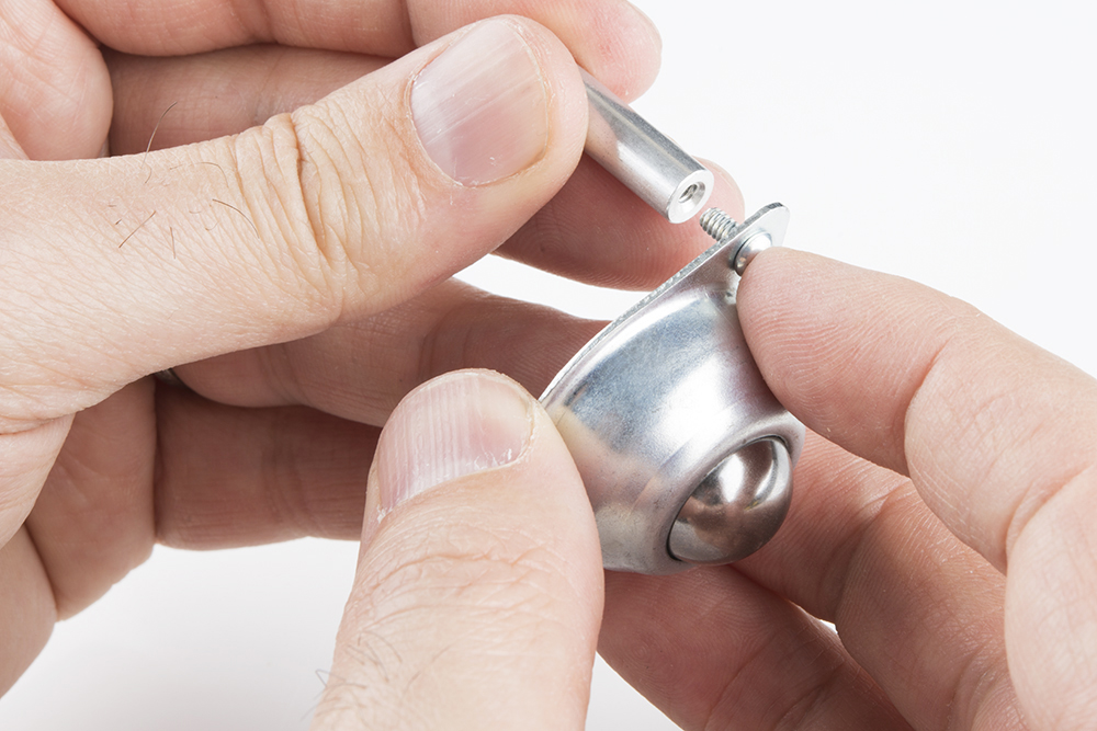
Place a 4-40 x 1/4" Phillips screw through one of the ball caster's holes. The screw's head should be on the same side as the ball caster's metal ball. Then, screw in one of the 4-40 x 1" metal standoffs to the metal ball caster.
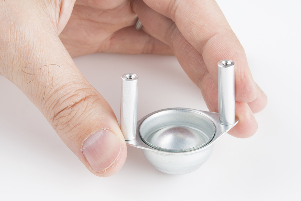
Using a 4-40 x 1/4" Phillips screw, screw on the second 4-40 x 1" metal standoff on the other side of the ball caster.
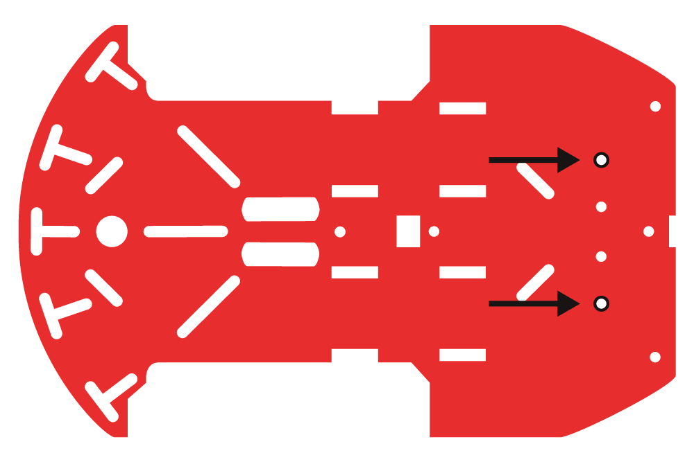
Locate the two positions on the chassis piece where you will be screwing down the metal ball caster.
Now, you can use two 4-40 x 1/4" Phillips screws to tighten down the metal ball caster to the bottom side of the chassis piece. The metal ball caster should be on the same chassis side as the motors.
In this section, you will be putting two wheels on the RedBot motors. It will start to look like a moveable robot!
| 2x Wheels |
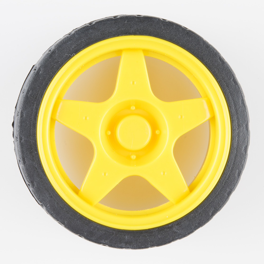 |
Simply place the two tires on the ends of the motors. No sweat needed to complete this step!
If you are having a hard time getting the wheels on, make sure to line up the inside notches of the wheel to the motor notches.
In this section, you will be putting standoffs on the RedBot Sensor - Line Followers. Then you will add the sensors to your chassis.
| 6x 4-40 x 1/4" Phillips Screw | 3x 4-40 x 1 1/2" Metal Hex Standoff |
|
 |
| 3x RedBot Sensor - Line Follower | 9x Jumper Wire |
 |
 |
Please note: ** Pay close attention to which screws you are using. There are two different screws in the RedBot Kit. (30x** of the 4-40 x 1/4" Phillips screws and 4x of the 4-40 x 1 1/4" flat head screws).
Adding the RedBot Sensor - Mechanical Bumper? You will have 3x of the 4-40 x ⅜" Phillips screws.
There are also different standoffs in the RedBot Kit and add-ons. The RedBot Kit comes with 7x 4-40 x 1" metal standoffs, 4x 4-40 x ⅜" metal standoff,s and 3x 4-40 x 1 1/2" metal hex standoff.s
Adding the RedBot Sensor - Mechanical Bumper? You will have 3x of the 4-40 x 3/4" nylon standoffs.
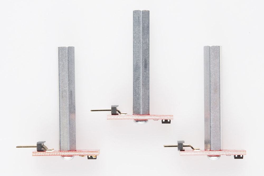
Place a 4-40 x 1/4" Phillips screw through one of the line followers. Then, twist on the 4-40 x 1 1/2" metal hex standoff. Make sure to tighten the standoff on the line follower's header side. The top of the screw should be on the same side as the line follower's sensor.
Do this for the other two line followers.
Locate three spots on the chassis where you will be adding the line followers.
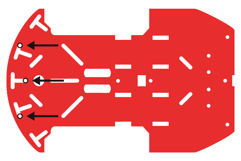
Place a 4-40 1/4" Phillips screw through the top side of the chassis piece. Tighten down the 4-40 x 1 1/2" metal hex standoff with a line follower into the bottom chassis piece. The line follower should be on the bottom side of the chassis piece. The headers on the line follower should be pointing in toward the chassis. Do this for the other two line followers.

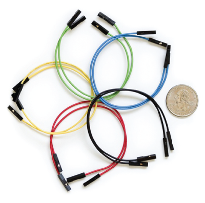
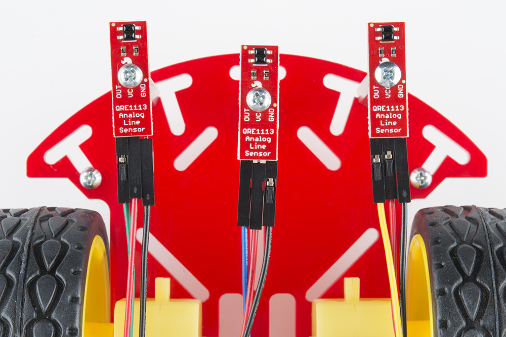
Time to add some jumper wires! You will need to connect a jumper wire to each female header pin on the line followers. There will be nine total jumper wires.
You do not need to have the same color jumper wires as this assembly guide. However, following along with the jumper wire colors in this assembly guide may be helpful if this is your first time assembling the RedBot. See below if you are following along with the jumper wire colors to help lessen confusion when hooking up the RedBot Mainboard later in the guide.
Left RedBot Sensor - Line Follower:
| Jumper Wires | Left RedBot Sensor - Line Follower |
|---|---|
| Jumper Wire - Yellow | OUT |
| Jumper Wire - Red | VCC |
| Jumper Wire - Black | GND |
Please note: When you have the RedBot upright and the front of the chassis facing north, the left line follower will be on the left side.
Middle RedBot Sensor - Line Follower:
| Jumper Wires | Middle RedBot Sensor - Line Follower |
|---|---|
| Jumper Wire - Blue | OUT |
| Jumper Wire - Red | VCC |
| Jumper Wire - Black | GND |
Right RedBot Sensor - Line Follower:
| Jumper Wires | Right RedBot Sensor - Line Follower |
|---|---|
| Jumper Wire - Green | OUT |
| Jumper Wire - Red | VCC |
| Jumper Wire - Black | GND |
Please note: When you have the RedBot upright and the front of the chassis facing north, the right line follower will be on the right side.
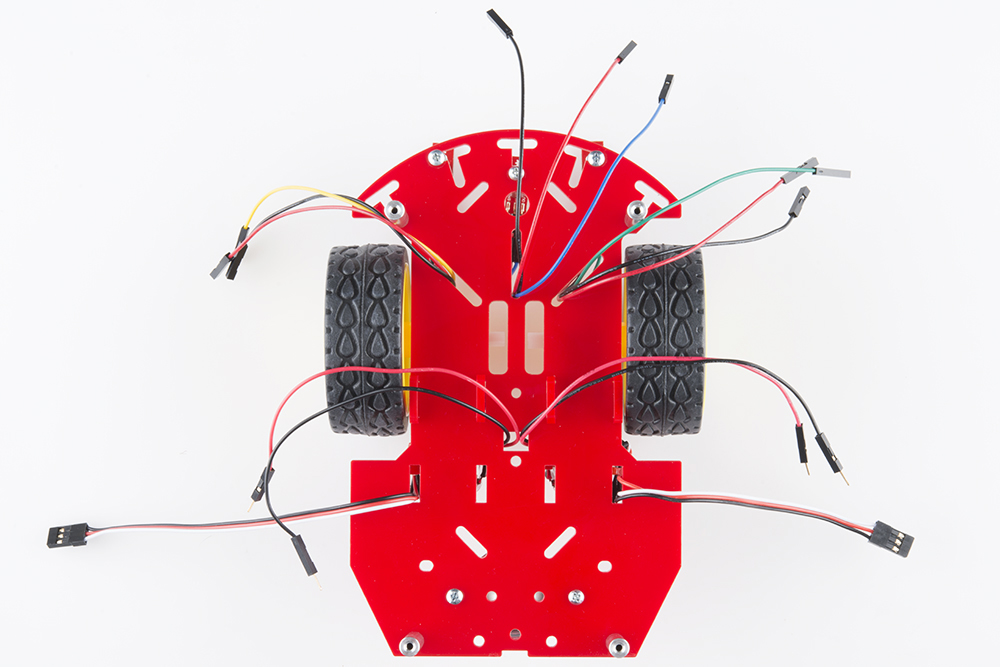
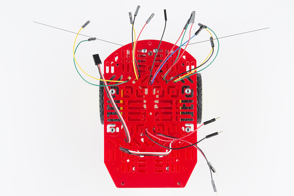
Here is the view from the bottom side:
Take the jumper wires and place them through the chassis openings. The jumper wires should be sticking out on the top side of the chassis. We recommend that each group of three jumper wires, for each line follower, goes in a different chassis opening as shown below. This helps keep track of the different jumper wires when connecting to the RedBot Mainboard later.
Read on if you are using the RedBot Sensor - Mechanical Bumpers. If not, skip to the next section.
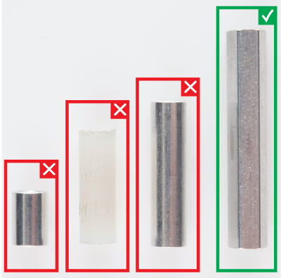
You will need to prepare the music wire by bending the wire itself. Then, you will add standoffs and screws to your mechanical bumpers, followed by adding the mechanical bumpers to the RedBot chassis.
| 6x 4-40 x 3/8" Phillips screw | 2x 4-40 x 3/4" Nylon Standoff | 2x 4-40 Hex Nut |
 |
 |
|
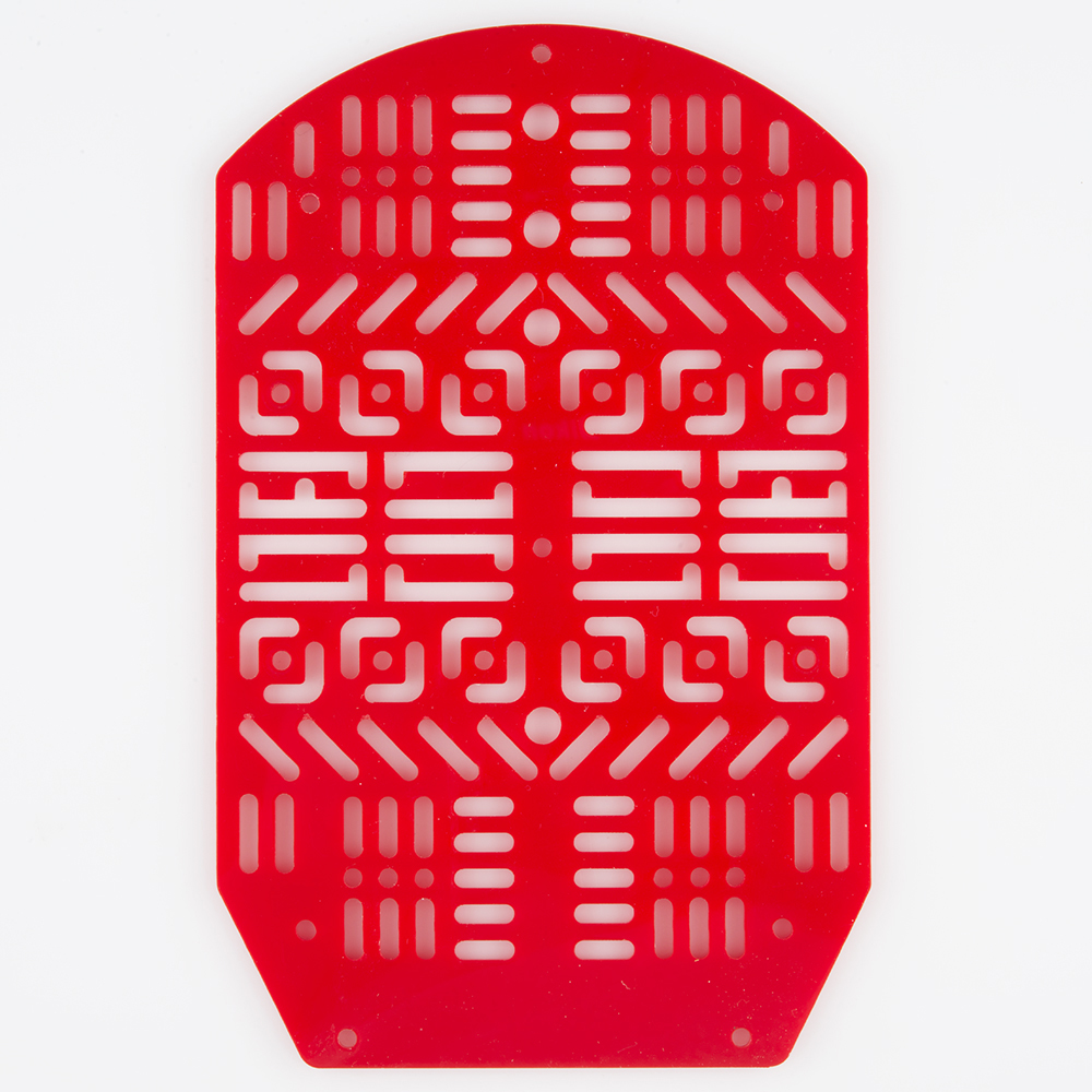
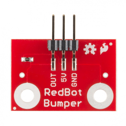
| 4x Jumper Wire | 1x RedBot Top Chassis | 2x RedBot Sensor - Mechanical Bumper |
|
 |
 |
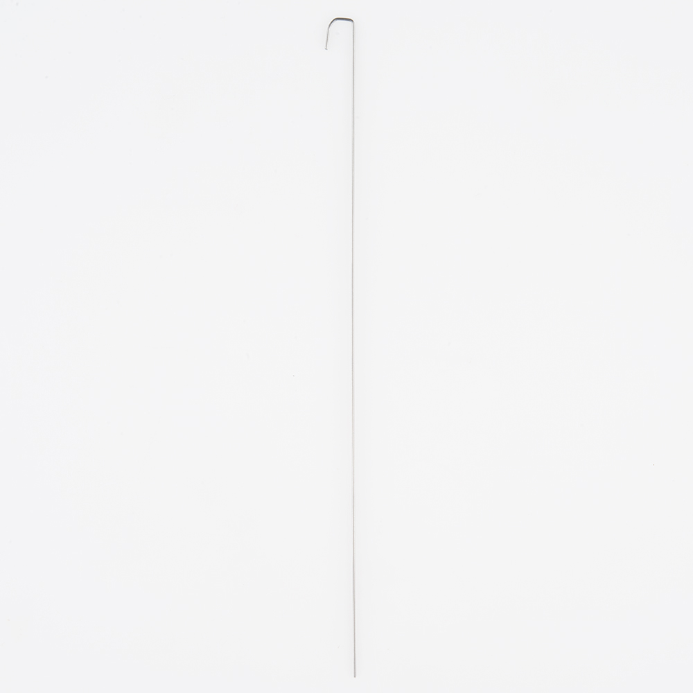
| 2x Whisker | ||
 |
Please note: ** Pay close attention to which screws you are using. There are two different screws in the RedBot Kit. (30x** of the 4-40 x 1/4" Phillips screws and 4x of the 4-40 x 1 1/4" flat head screws).
Adding the RedBot Sensor - Mechanical Bumper? You will have 3x of the 4-40 x ⅜" Phillips screws.
There are also different standoffs in the RedBot Kit and add-ons. The RedBot Kit comes with 7x 4-40 x 1" metal standoffs, 4x 4-40 x ⅜" metal standoffs, and 3x 4-40 x 1 1/2" metal hex standoffs.
Adding the RedBot Sensor - Mechanical Bumper? You will have 3x of the 4-40 x 3/4" nylon standoffs.
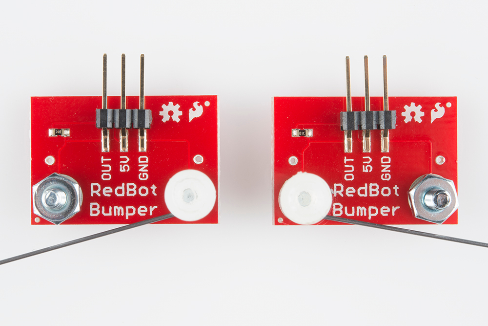
Screw a 4-40 x ⅜" Phillips screw and 4-40 hex nut to one of the two large mechanical bumper holes.
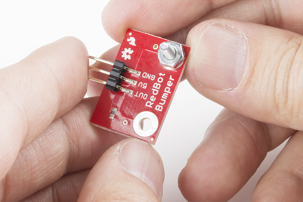
Time to bend the whisker! It is easy to bend the whisker with needle nose pliers. However, there is a trick to bend the whisker using the mechanical bumper PCB itself. First, stick one of the whiskers through one of the smaller side holes. It only needs to stick out a little bit.

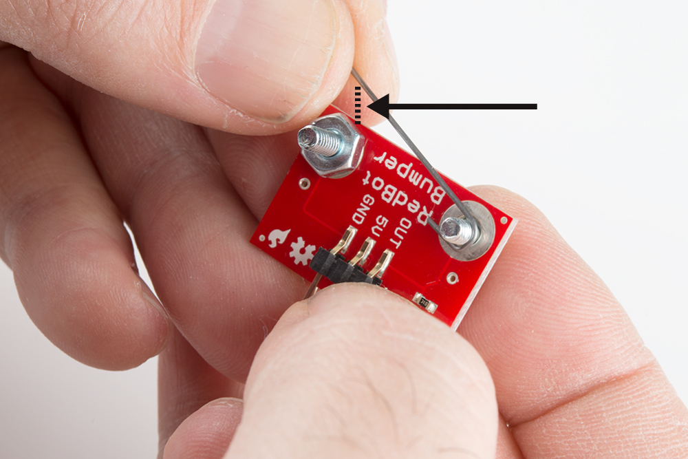
Bend the whisker 90 degrees.

Bend the whisker 90 degrees again.

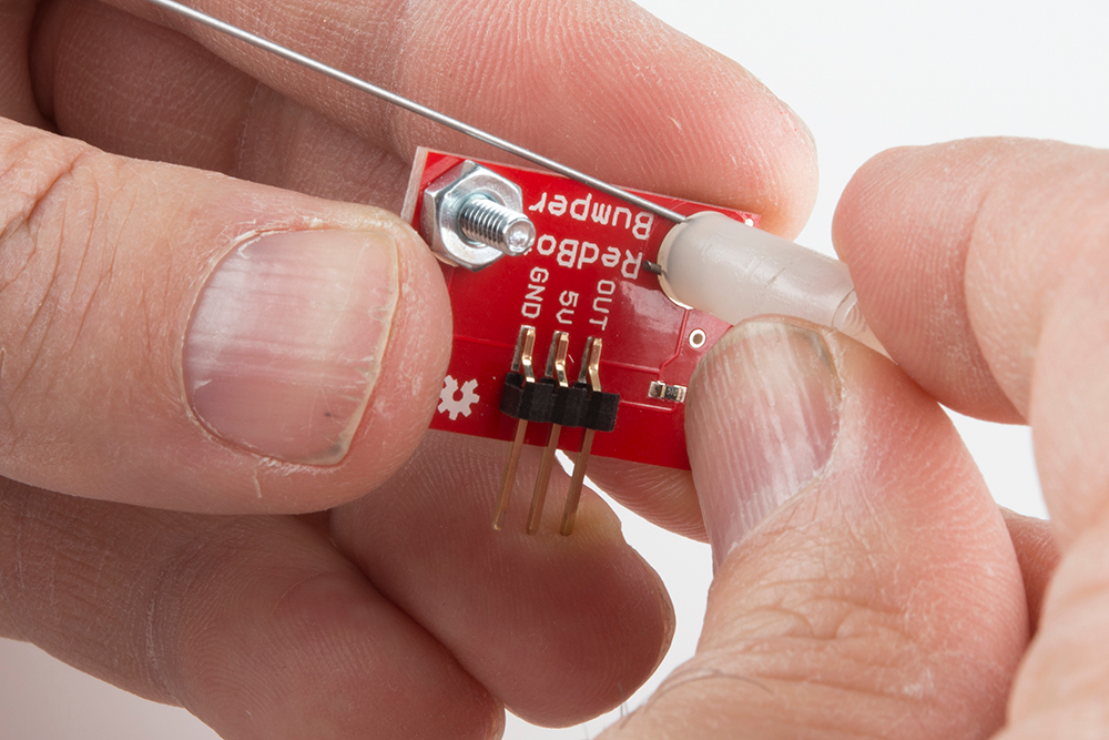
Now that the whisker is bent, take the wire out of the PCB hole. Add a 4-40 x ⅜" Phillips Screw from the bottom and loop the bent whisker around the screw. It is very important that you do not let the whisker touch the other side's 4-40 hex nut and 4-40 x ⅜" Phillips screw, since that is what triggers the sensor. Leave a little space between the wire and other side's nut.
Twist a 4-40 x 3/4" nylon standoff on top of the screw to secure the wire.
Double check that the wire does not touch the other side's 4-40 hex nut and 4-40 x ⅜" Phillips screw.
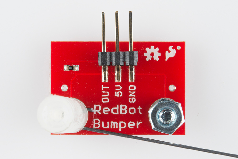
Do this for the other mechanical bumper. Take note of which side your 4-40 x 3/4" nylon standoff is on for the first mechanical bumper. Do the opposite for the other bumper. Double check that there is one mechanical bumper that has a 4-40 x 3/4" nylon standoff on the right side of the "RedBot Bumper" silkscreen and one that has a 4-40 x 3/4" nylon standoff on the left side.
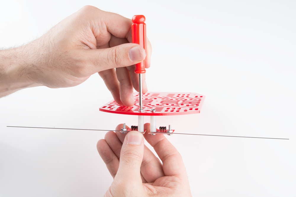
Locate the two positions on the top chassis piece.
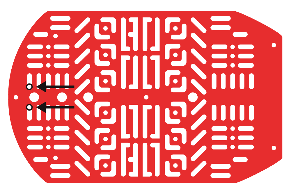
Using two 4-40 x 1/4" Phillips screws, tighten down the mechanical bumpers with the two wires pointing in opposite directions on the bottom side of the top chassis piece. The mechanical bumpers' header pins should be pointing toward the chassis piece.
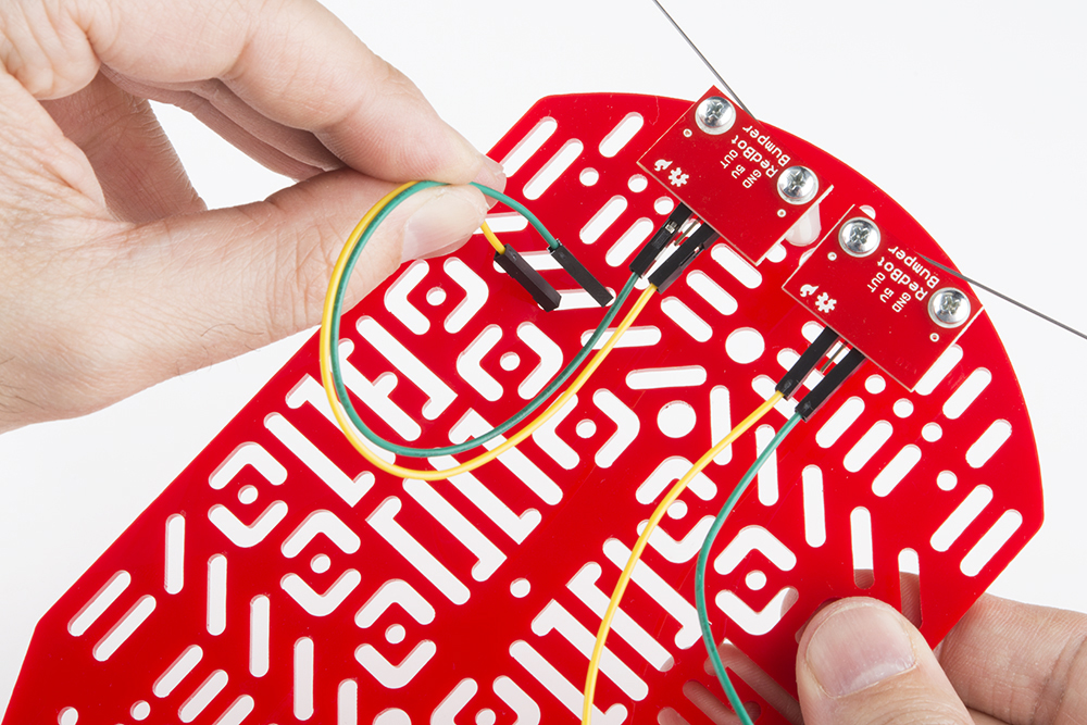
Add jumper wires to the GND and OUT pins on both of the mechanical bumpers. You will not add jumper wires to the 5V pins. Again, which color jumper wires you choose does not matter, but it might be helpful to follow along with this assembly guide.
Left RedBot Sensor - Mechanical Bumper:
| Jumper Wires | Left RedBot Sensor - Mechanical Bumper |
|---|---|
| Jumper Wire - Green | GND |
| Jumper Wire - Yellow | OUT |
Please note: When you have the RedBot upright and the front of the chassis facing north, the left mechanical bumper will be on the left side.
Right RedBot Sensor - Mechanical Bumper:
| Jumper Wires | Right RedBot Sensor - Mechanical Bumper |
|---|---|
| Jumper Wire - Yellow | GND |
| Jumper Wire - Green | OUT |
Please note: When you have the RedBot upright and the front of the chassis facing north, the right mechanical bumper will be on the right side.
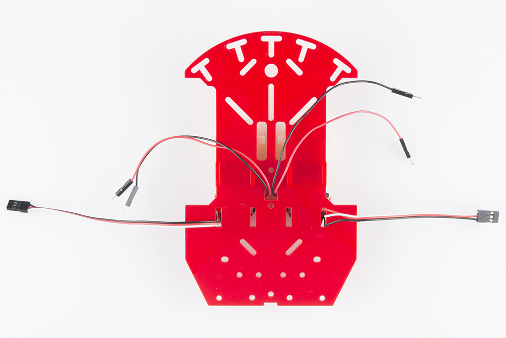
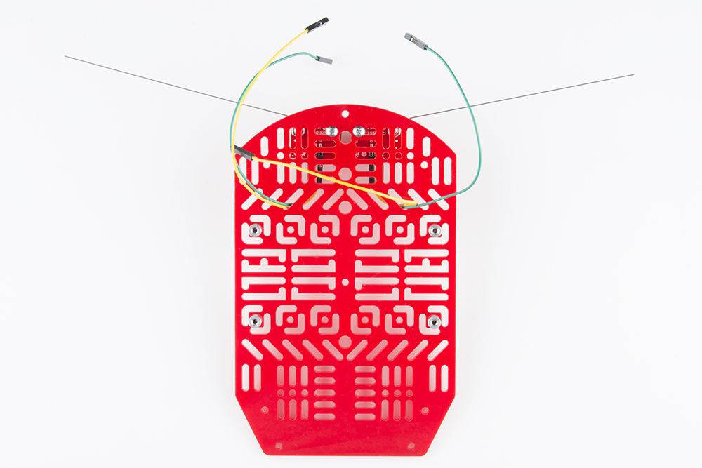
Here is the view from the bottom side:

Put the other ends of the jumper wires through the top chassis piece.
Make sure the jumper wires are all the way through.

Time to add the standoffs! Adding the standoffs will allow us to connect the top and bottom chassis pieces.
| 12x 4-40 x 1/4" Phillips Screw | 4x 4-40 x 3/8" Metal Standoff | 4x 4-40 x 1" Metal Standoff |
|
 |
|
Please note: ** Pay close attention to which screws you are using. There are two different screws in the RedBot Kit. (30x** of the 4-40 x 1/4" Phillips screws and 4x of the 4-40 x 1 1/4" flat head screws).
Adding the RedBot Sensor - Mechanical Bumper? You will have 3x of the 4-40 x ⅜" Phillips screws.
There are also different standoffs in the RedBot Kit and add-ons. The RedBot Kit comes with 7x 4-40 x 1" metal standoffs, 4x 4-40 x ⅜" metal standoffs, and 3x 4-40 x 1 1/2" metal hex standoffs.
Adding the RedBot Sensor - Mechanical Bumper? You will have 3x of the 4-40 x 3/4" nylon standoffs.
Find the following locations on the top chassis piece where you will add four 4-40 x ⅜" metal standoffs.
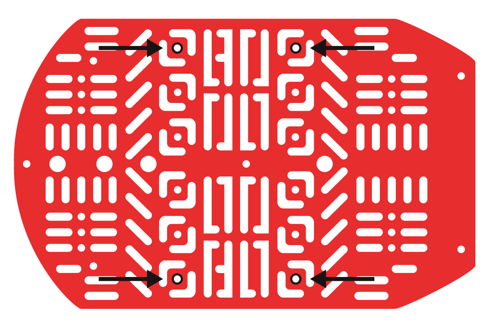
Using the 4-40 x 1/4" Phillips screws, add all four 4-40 x ⅜" metal standoffs on the top chassis piece.
In order to connect the top chassis piece to the bottom piece, you will need to put standoffs between the two chassis pieces. Follow along to see the best locations to place the metal standoffs.
Find the four 4-40 x 1" metal standoff locations.
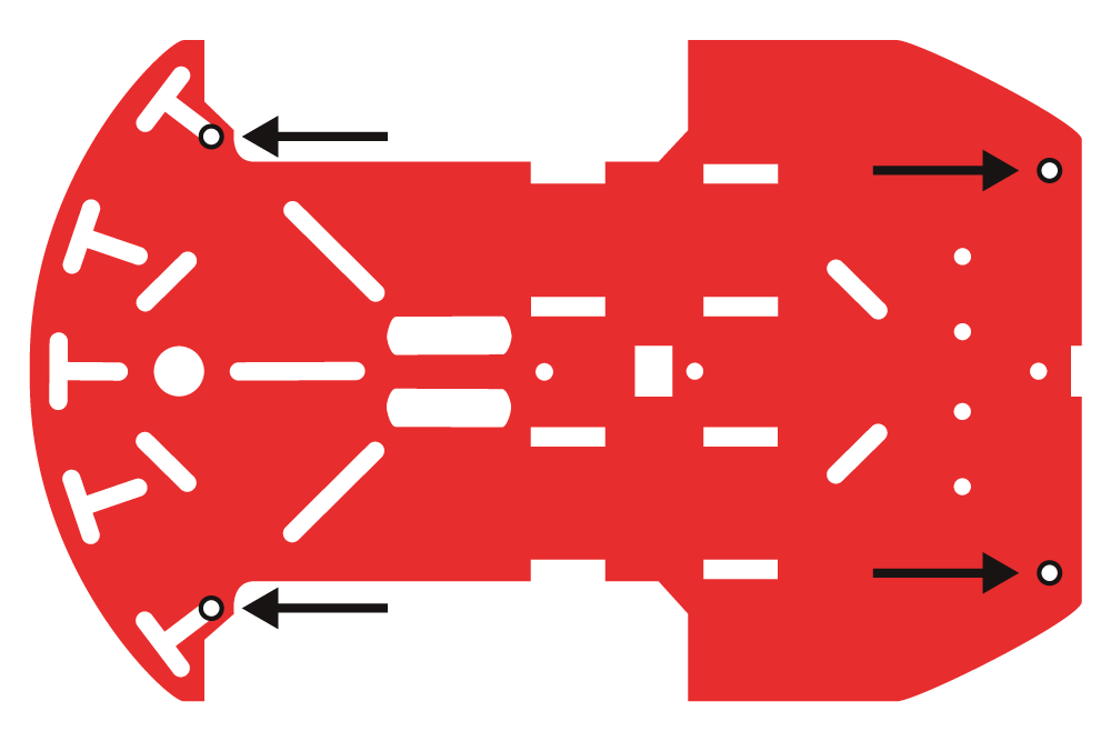
Using 4-40 x 1/4" Phillips screws, tighten down all four 4-40 x 1" metal standoffs on the top side of the bottom chassis piece.
Now it is time to connect the top chassis piece to the bottom chassis piece. First, push all the jumper wires through the top chassis piece. Make sure the top chassis piece has the 4-40 x ⅜" metal standoffs at the very top. Also, pay attention that both chassis pieces' front and back sides line up and are correct.
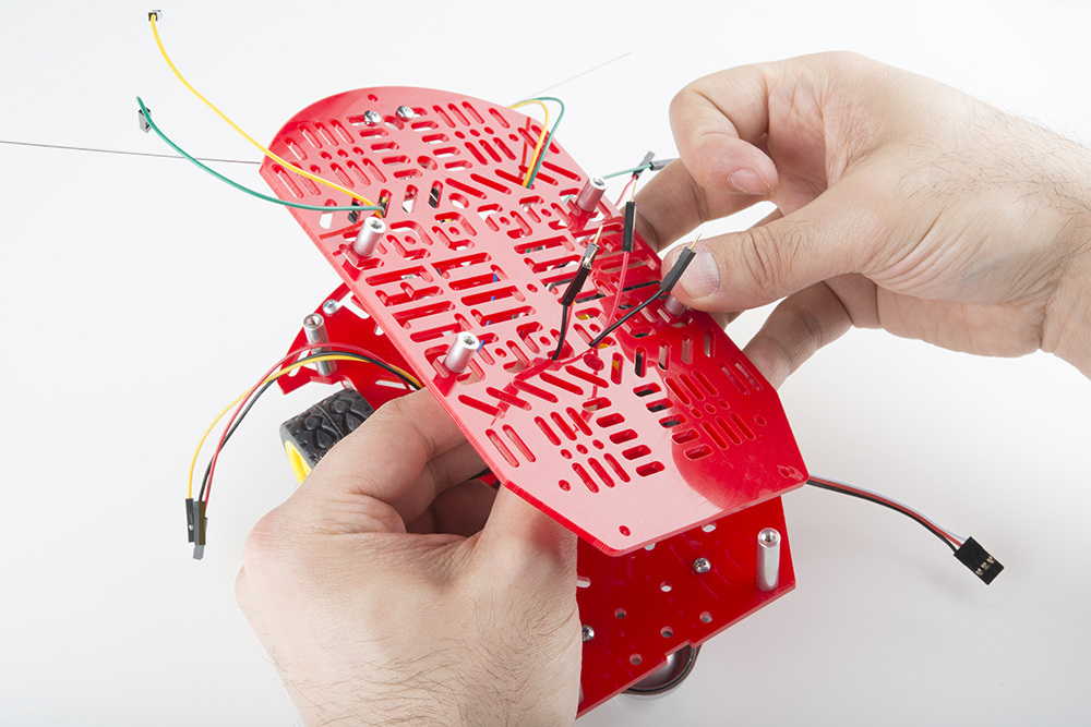
Push the jumper wires all the way through the top.
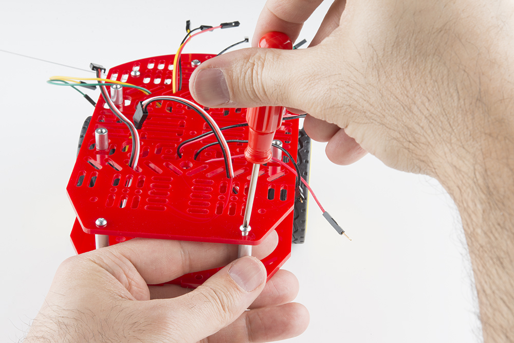
All the jumper wires should now be through the top. Using the 4-40 x 1/4" Phillips screws, screw down the top chassis piece to the 4-40 x 1" metal standoffs already on the bottom chassis piece.
In this section, you will adding the brains of the robot: the RedBot Mainboard.
| 4x 4-40 x 1/4" Phillips Screw | 1x RedBot Mainboard |
|
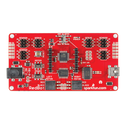 |
Line up the four corner holes of the RedBot Mainboard to the four 4-40 x ⅜" metal standoffs on the top chassis piece. You will want the barrel jack on the RedBot Mainboard to be on the left side. Using four 4-40 x 1/4" Phillips screws, tighten down the RedBot Mainboard to the four 4-40 x ⅜" metal standoffs.
Your robot needs power! In this section, you will be adding the battery holder to the RedBot.
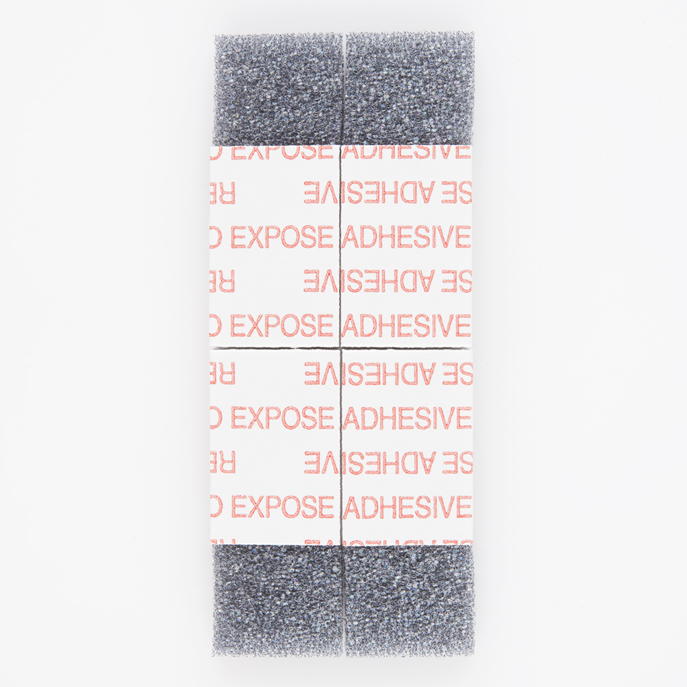
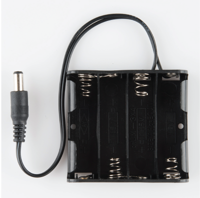
| 4x Pieces of Double-Sided Sticky Foam Tab | 1x Battery Holder |
 |
 |
Peel and stick one tab of double-sided sticky foam to the back side of the top chassis piece.
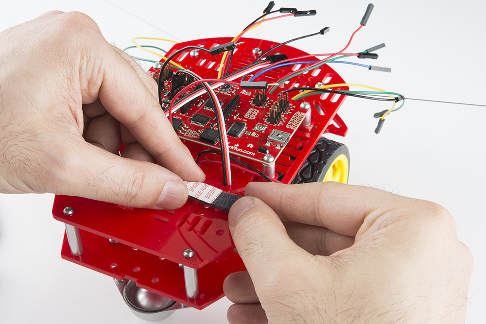
Add the other three tabs of double-sided sticky foam to the back side of the top chassis piece.
Peel off the tops of all the tabs of double-sided sticky foam. Then place the battery holder on top. The battery holder barrel jack connector should be on the same side (left side) as the RedBot Mainboard's barrel jack connector.
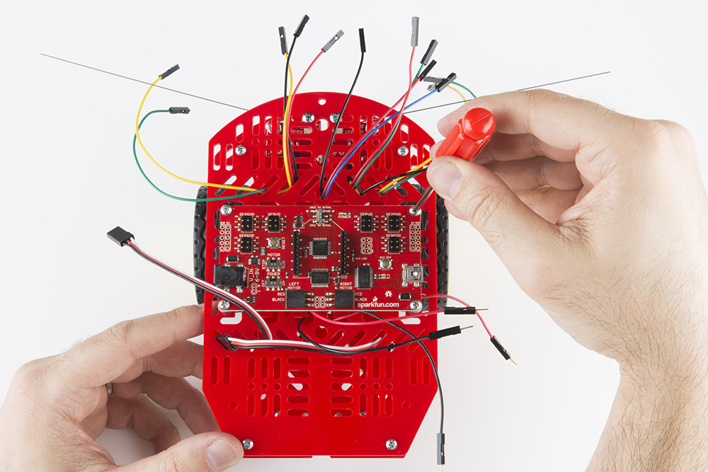
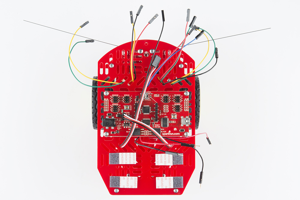
Now that you have the top chassis piece down, it is time to connect the jumper wires - it's really important that the connections are right. Please remember that the jumper wire color is meant to help lessen confusion when making connections. However, the actual color of jumper wires does not matter as long as the connections from pin to pin are correct.
You can follow along with the pin out tables or scroll down for a Fritzing image.
Left RedBot Sensor - Line Follower:
| RedBot Mainboard Pins | Jumper Wires | Left RedBot Sensor - Line Follower |
|---|---|---|
| A3 | Jumper Wire - Yellow | OUT |
| 5V | Jumper Wire - Red | VCC |
| GND | Jumper Wire - Black | GND |
Please note: When you have the RedBot upright and the front of the chassis facing north, the left line follower will be on the left side.
Middle RedBot Sensor - Line Follower:
| RedBot Mainboard Pins | Jumper Wires | Middle RedBot Sensor - Line Follower |
|---|---|---|
| A6 | Jumper Wire - Blue | OUT |
| 5V | Jumper Wire - Red | VCC |
| GND | Jumper Wire - Black | GND |
Right RedBot Sensor - Line Follower:
| RedBot Mainboard Pins | Jumper Wires | Right RedBot Sensor - Line Follower |
|---|---|---|
| A7 | Jumper Wire - Green | OUT |
| 5V | Jumper Wire - Red | VCC |
| GND | Jumper Wire - Black | GND |
Please note: When you have the RedBot upright and the front of the chassis facing north, the right line follower will be on the right side.
Left RedBot Sensor - Mechanical Bumper:
| RedBot Mainboard Pins | Jumper Wires | Left RedBot Sensor - Mechanical Bumper |
|---|---|---|
| GND | Jumper Wire - Green | GND |
| 3 | Jumper Wire - Yellow | OUT |
Please note: When you have the RedBot upright and the front of the chassis facing north, the left mechanical bumper will be on the left side.
Right RedBot Sensor - Mechanical Bumper:
| RedBot Mainboard Pins | Jumper Wires | Right RedBot Sensor - Mechanical Bumper |
|---|---|---|
| 11 | Jumper Wire - Yellow | GND |
| GND | Jumper Wire - Green | OUT |
Left Motor:
| RedBot Mainboard Pins | Left Motor Jumper Wires |
|---|---|
| RED | Soldered on Motor Jumper Wire - RED |
| BLACK | Soldered on Motor Jumper Wire - Black |
Please note: When you have the RedBot upright and the front of the chassis facing north, the left motor will be on the left side.
Right Motor:
| RedBot Mainboard Pins | Right Motor Jumper Wires |
|---|---|
| RED | Soldered on Motor Jumper Wire - RED |
| BLACK | Soldered on Motor Jumper Wire - Black |
Please note: When you have the RedBot upright and the front of the chassis facing north, the right motor will be on the right side.
Left Wheel Encoder:
| RedBot Mainboard Pins | Left Wheel Encoder Jumper Wires |
|---|---|
| A2 | Wheel Encoder Jumper Wire - White |
| 5V | Wheel Encoder Jumper Wire - RED |
| GND | Soldered on Motor Jumper Wire - Black |
Please note: When you have the RedBot upright and the front of the chassis facing north, the left wheel encoder will be on the left side.
Right Wheel Encoder:
| RedBot Mainboard Pins | Right Wheel Encoder Jumper Wires |
|---|---|
| 10 | Wheel Encoder Jumper Wire - White |
| POW | Wheel Encoder Jumper Wire - RED |
| GND | Wheel Encoder Jumper Wire - Black |
Please note: When you have the RedBot upright and the front of the chassis facing north, the right wheel encoder will be on the right side.

Time to add the RedBot accelerometer! If you do not have headers on your accelerometer already (older revisions of the RedBot accelerometer did not have headers), we recommend soldering on female headers to your accelerometer to fit on top of the RedBot Mainboard's female headers.
| 1x RedBot Accelerometer |
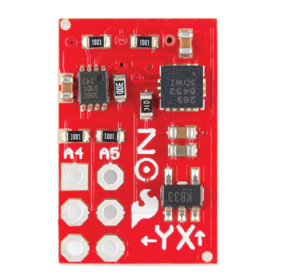 |
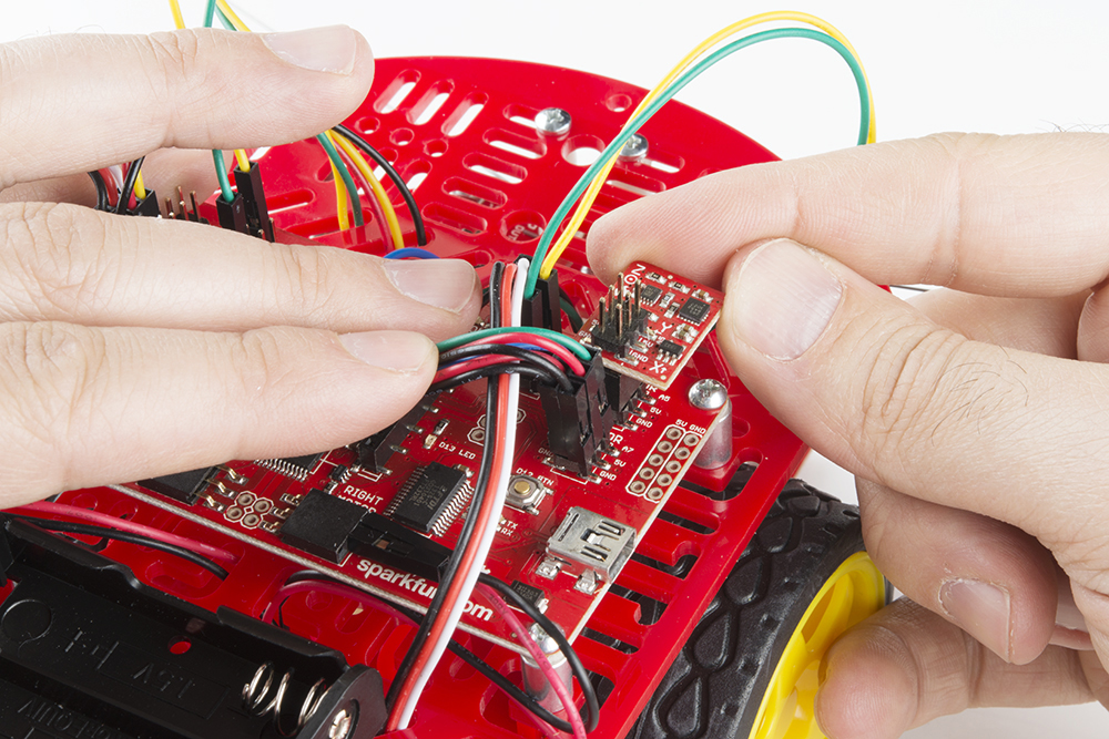
Locate the position on the RedBot Mainboard to add the accelerometer. Line up the "A4" pin on the accelerometer to the "A4" male header pin in the "SENSOR" section on the RedBot Mainboard.
Read on if you are using the RedBot buzzer. If not, skip to the next section.
Adding the RedBot buzzer is nice and easy!
| 1x RedBot Buzzer |
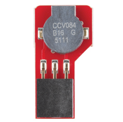 |
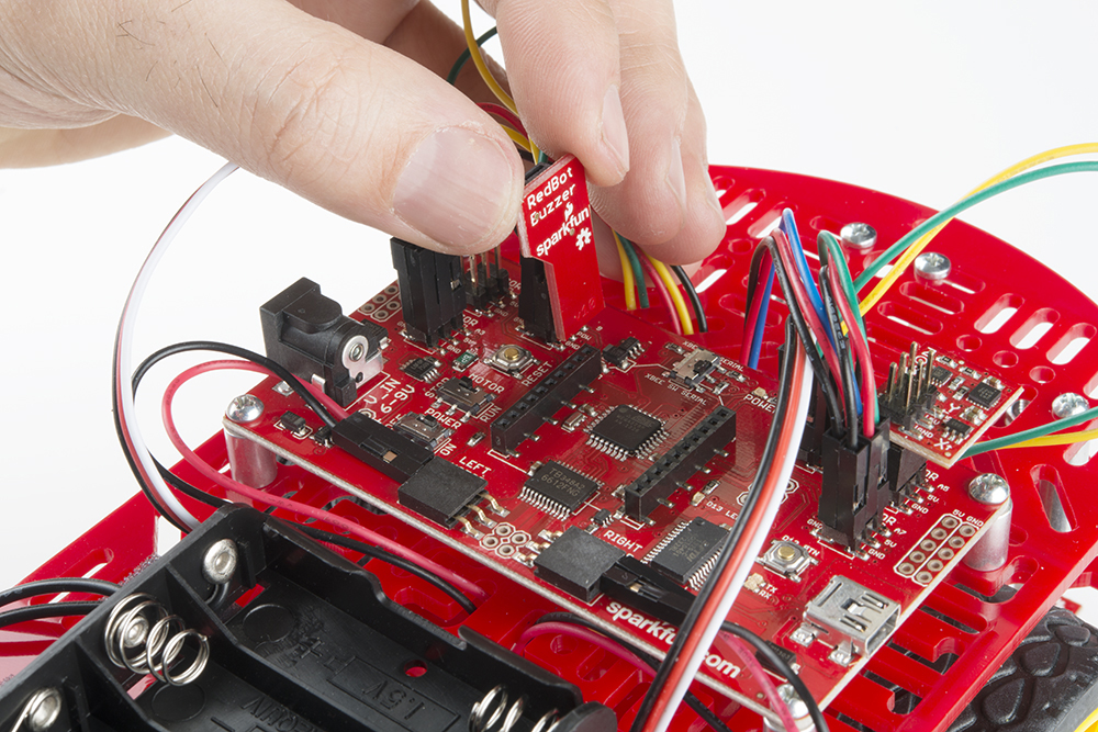
Locate the position on the RedBot Mainboard to add the RedBot buzzer. With the buzzer side and female header PCB side of the RedBot buzzer facing to the left, place the RedBot buzzer on top of the "9," "POW," and "GND" male header pin row in the "SERVO" section on the RedBot Mainboard.
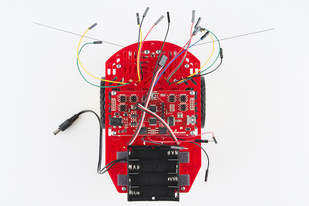
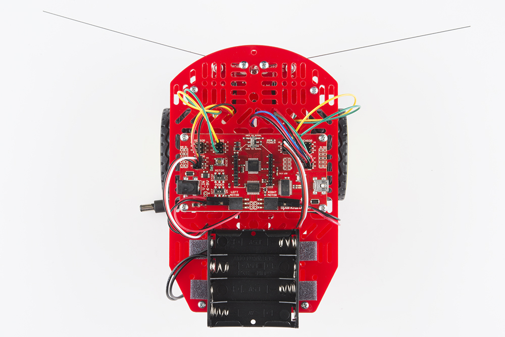
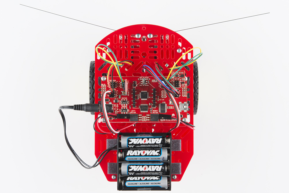
Whew, you are so close to being done! Time to add 4x AA batteries and plug in the battery holder.
Use the graphics on the battery holder to place the batteries in the correct orientation. Plug in the battery holder's barrel power plug into the barrel power jack on the RedBot Mainboard.
What a rock star! With all that building, we bet you are ready to start cruising. Check out the following tutorials to help you get started with the RedBot.
learn.sparkfun.com | CC BY-SA 3.0 | SparkFun Electronics | Niwot, Colorado