Have you ever wanted to merge technology with your dance? In this tutorial, you will learn how to design and build a wearable LED harness for dance performances. The design is not just limited to dance. You can also use it as a guide for costumes.
To follow along with this tutorial, you will need the following materials. You may not need everything though depending on what you have. Add it to your cart, read through the guide, and adjust the cart as necessary.
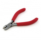
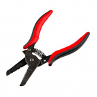
You will need a soldering iron, solder, general soldering accessories, and tools to work with wire.
You will also need:
If you aren’t familiar with the following concepts, we recommend checking out these tutorials before continuing.
Designing wearable electronics around a dancer is difficult depending on the movement. As a bboy, just about every part of the body is used on the floor.

So when planning for a show using wearable electronics, it needs to be:
On top of that, I needed to make enough for each student in my troupe. I decided make a harness to hold the electronics based on a backpack's shoulder straps. A button up shirt was used to diffuse the light. A bowtie and pocket square were added for detail.
For the scope of the tutorial, I'll be focusing on the harness to hold the LEDs and the electronics.
I debated with using either EL wire or LEDs. Each have different uses depending on the performance and lighting of the environment.
With the first wearable design for dance, I found that EL was harder to see with ambient lighting even with EL tape and panel. I was also limited to one color at a time. However, it required less power and it did have a different affect. For the second design, the LEDs were easier to see with the ambient light and I was able to select more than one color. The LEDs did require a little bit more power.
 |
 |
| Mark I: EL Dance Shirt | Mark II: LED Dance Harness |
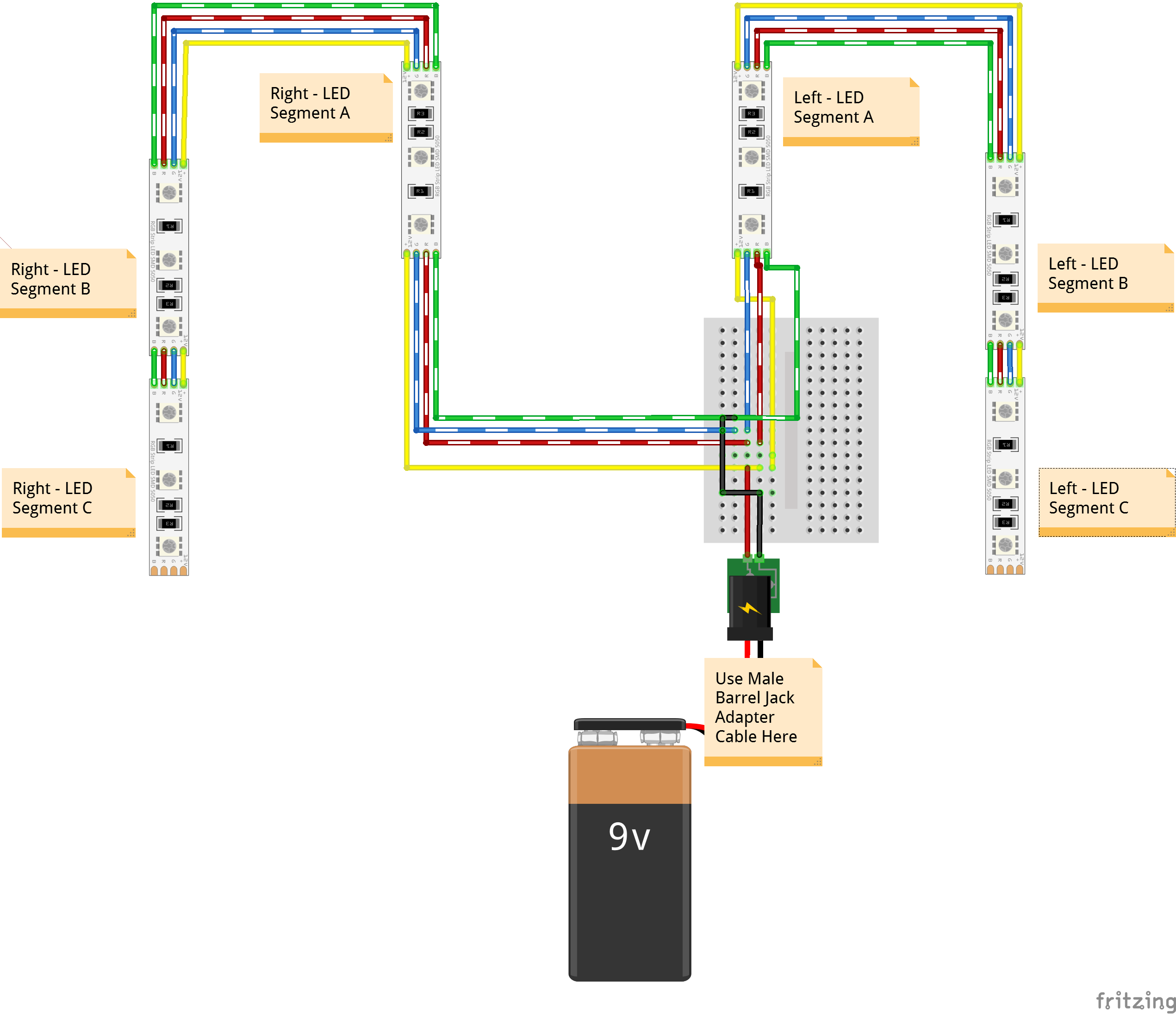
The circuit for the wearable LED harness is simple. Let's take a look at the left side of the harness that holds the battery, adapters, and LEDs.
Power is connected to the "+12V" pad of the non-addressable LED strip. To complete the circuit and power the LEDs, ground is connected to each color's pad labeled "G," "R", or "B." Green and blue were chosen to make cyan from the primary colors. For one side of the harness, LED segment A consisted of a long strip of 33x LEDs. LED segment B and C consisted of 3x LEDs each.
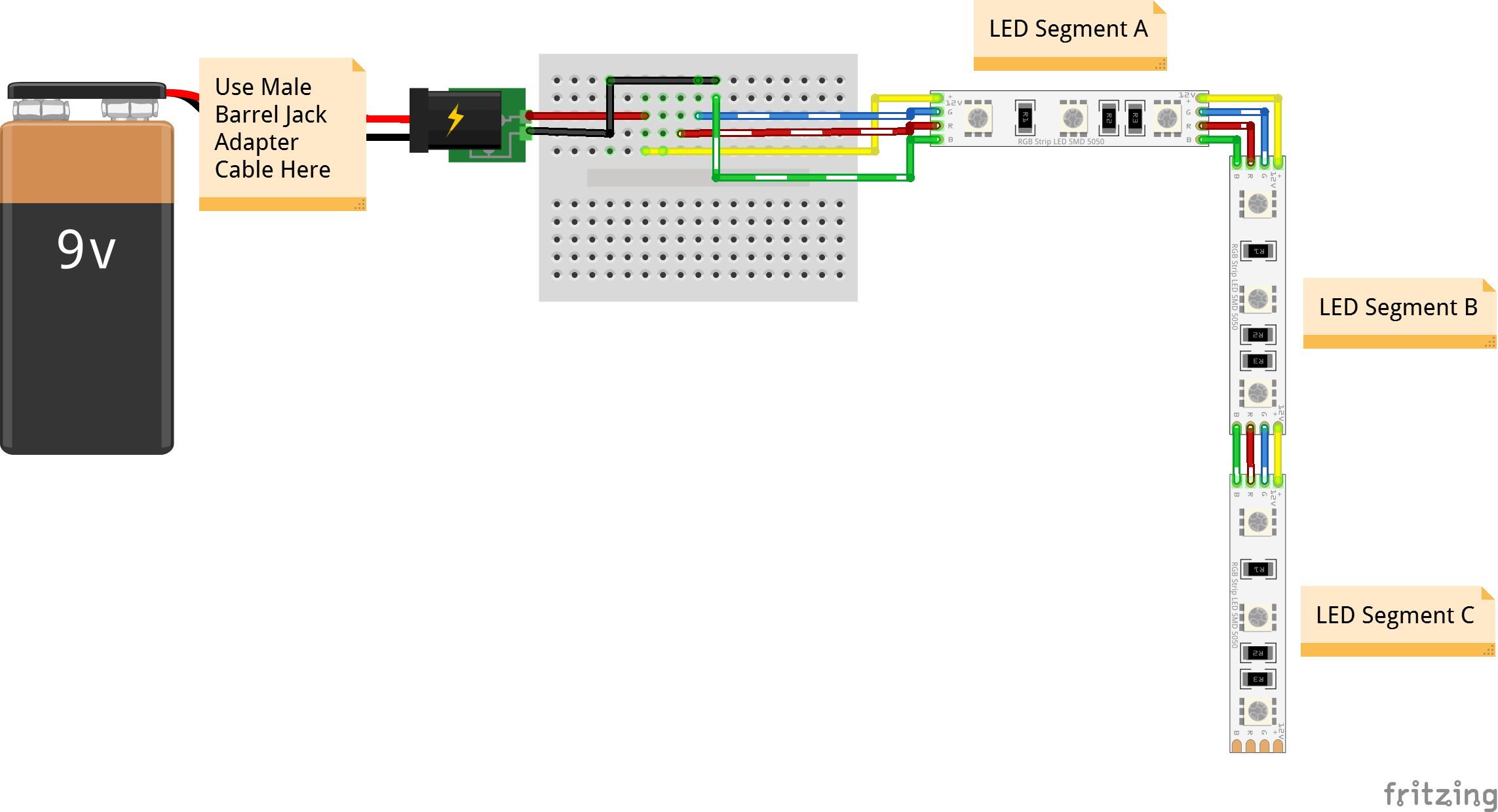
A 9V battery and custom made adapters were used for each harness. Keep in mind that a 9V battery is not able to power all three colors simultaneously. However, using two colors was sufficient enough for the project and performance.
The connection was then wired in parallel on the other side of the harness by connecting to the same rails on the solderable breadboard.
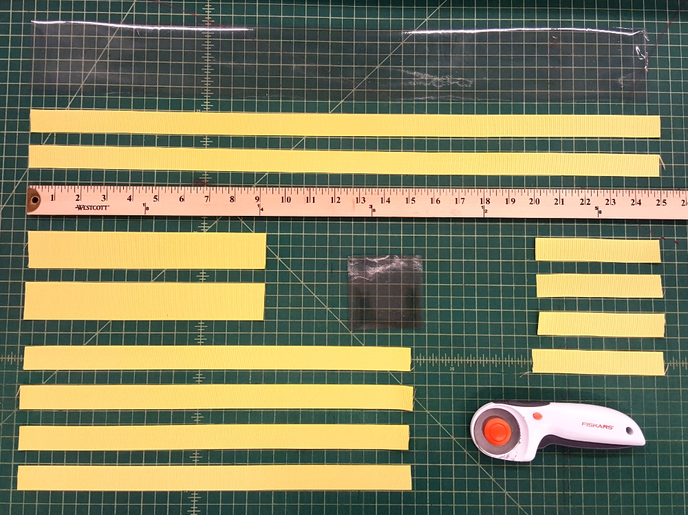
From the image shown below, prepare the fabric based on the user's height by cutting the ribbons and transparent vinyl. Carefully heat the ribbon ends with lighter to prevent the ends from unraveling. Listed below are the average lengths used for a kid.
Pin down the bottom of the harness and sew the ends together in a square pattern with a needle and thread.
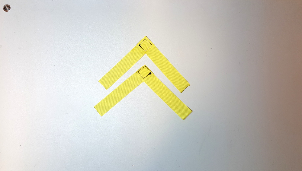
Pin and sew the bottom of the harness with the longer piece of ribbon. Make sure to sew the end in a triangular or square pattern to secure the ribbon.
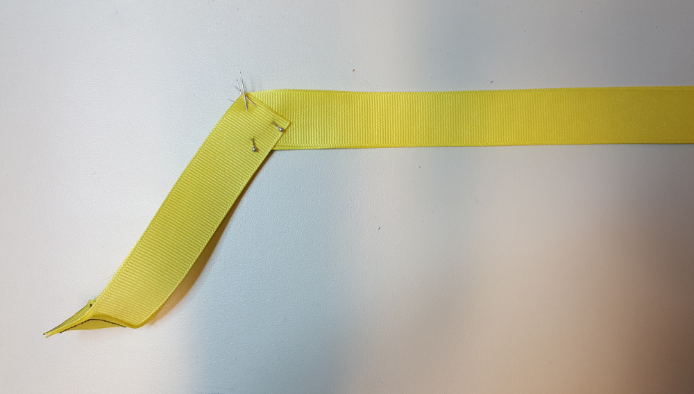
Make sure that the ribbon is flat and facing the same direction when sewing the top and bottom together. They should be free from any twists.

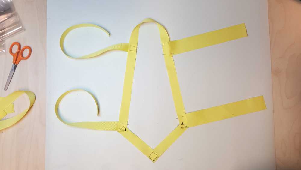
Starting with the right side of the harness, pin and sew the ribbon ties for the sternum and waist. The ribbon tie for the chest was about 10 inches above the waist. The ribbon tie for the waist was added to the bottom of the long strip. Repeat for the left side. Choosing one side of the harness, attatch the back ribbons using the same 10 inch spacing as the ribbon ties.
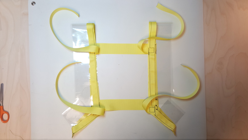
At this time, sew the opposite side to the harness. Using pins and a sewing machine, sew clear vinyl to the inside of the ribbon to the top and bottom each side. The vinyl should wrap around the LEDs and end behind the LEDs.

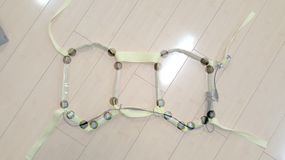
The completed harness should look like the image below.
Cut the LED strip at the center of the exposed pads using a diagonal cutter. The dot and dashed line in the image below is where you will need to perform the cut. Make sure to remove part of the silicone tube in order to be able to access the LED Strip's pads.

Cut half of the 12" premium jumper wires and strip the insulation. Then solder the wires to each of the LED strip's pads.
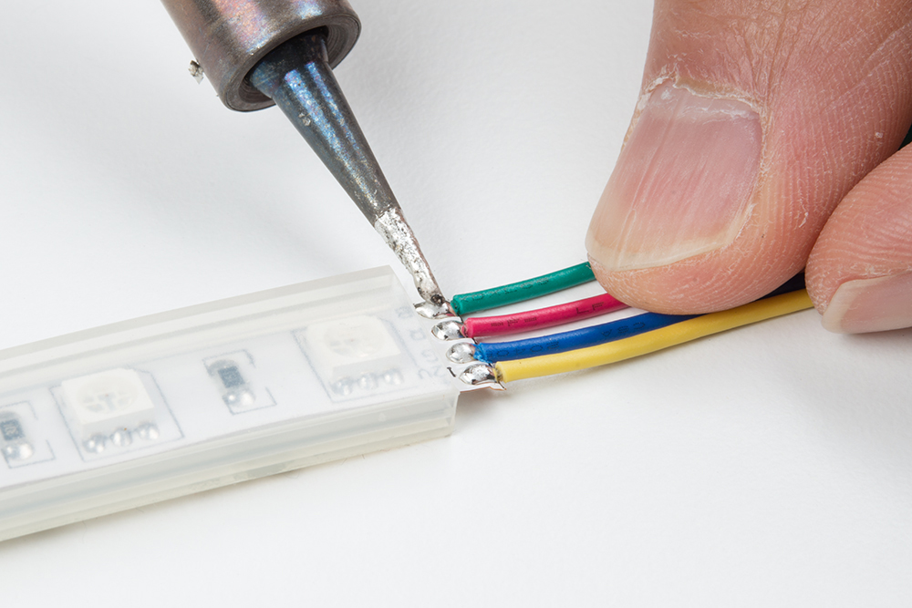
The connection to the pads needed to be secure so I decided to braid the wires together to manage the connections. I was inspired by McCall’s tutorial when completing projects. To braid your wires, twist a pair of wires in a counterclockwise pattern between your index finger and thumb using both hands. I decided to start with the green and red wires.
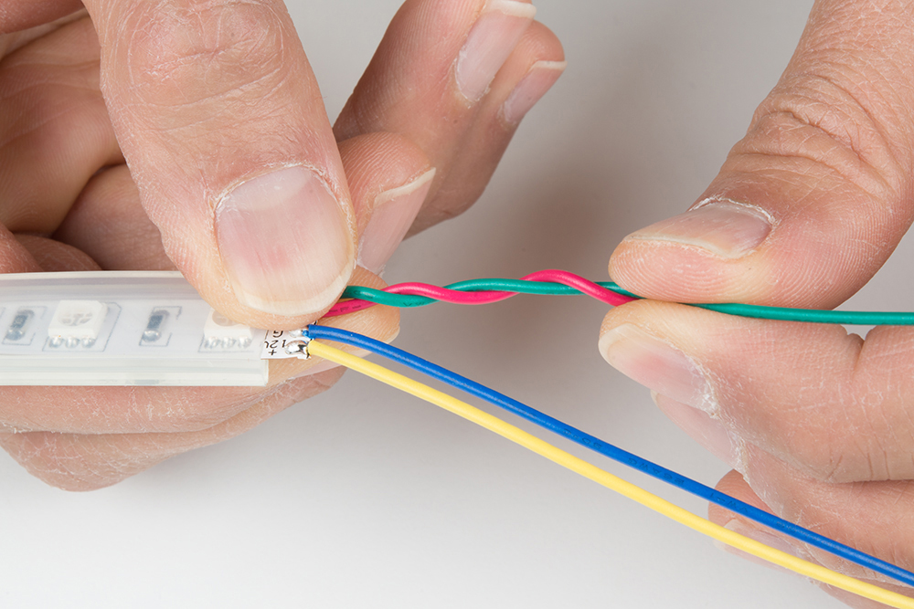
Twist the other pair of wires in a counterclockwise pattern.
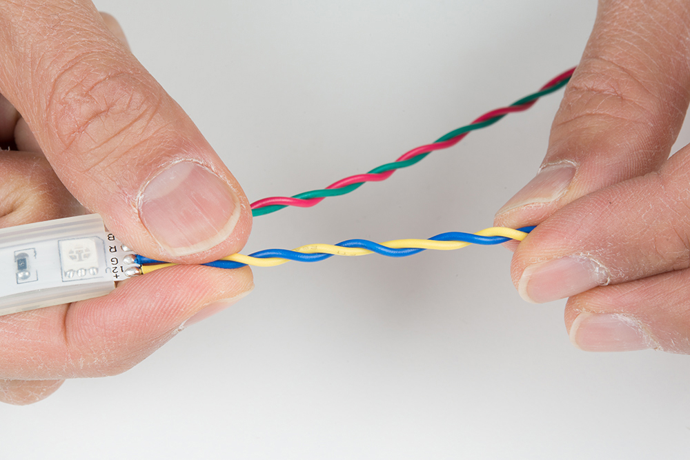
Twist the pairs of wires in a clockwise pattern.
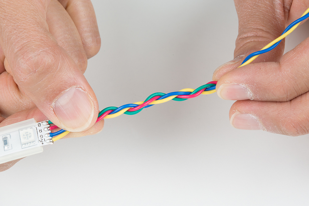
Repeat for segment B and C. The segments will be using shorter wire.
|
|
|
If you were using water soluble flux, clean the solder joints with de-ionized water and a toothbrush. Dry the LED strips thoroughly using compressed air. Luckily, SparkFun has a PCB cleaning room. As an alternative, you could use water from the sink and towels.

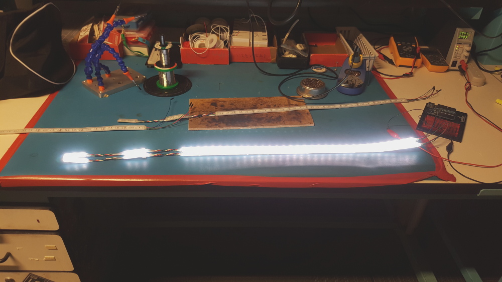
Once dry, test the LED strips to make the colors matched and the wires are connected to its respective pads. I decided to use a benchtop power supply set to output about 9V to verify the connection.
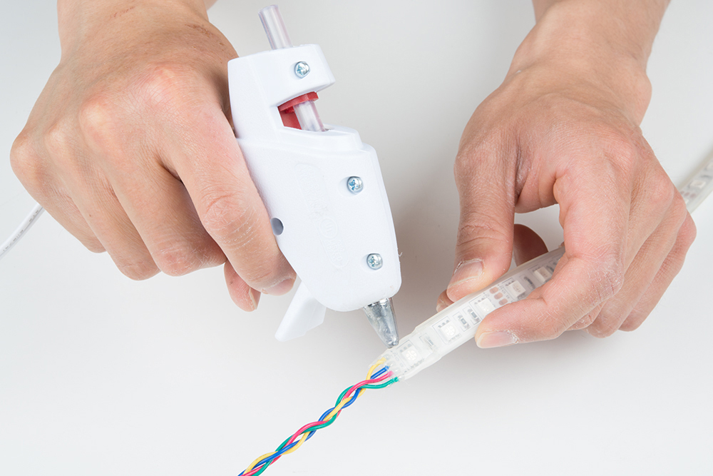
Add hot glue to the terminals to secure the wires further.
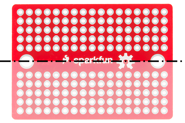
Using a dremel and Panavise, carefully cut the solderable breadboard in half.
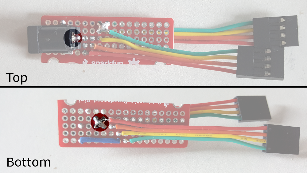
Solder the female barrel jack connector to the board so that the connector is flush with the edge.

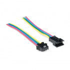
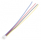
Cut the 1x4 pin jumper wire in half and strip each wire using 0.1" spacing. Solder the wires as illustrated earlier in the Fritzing diagram.
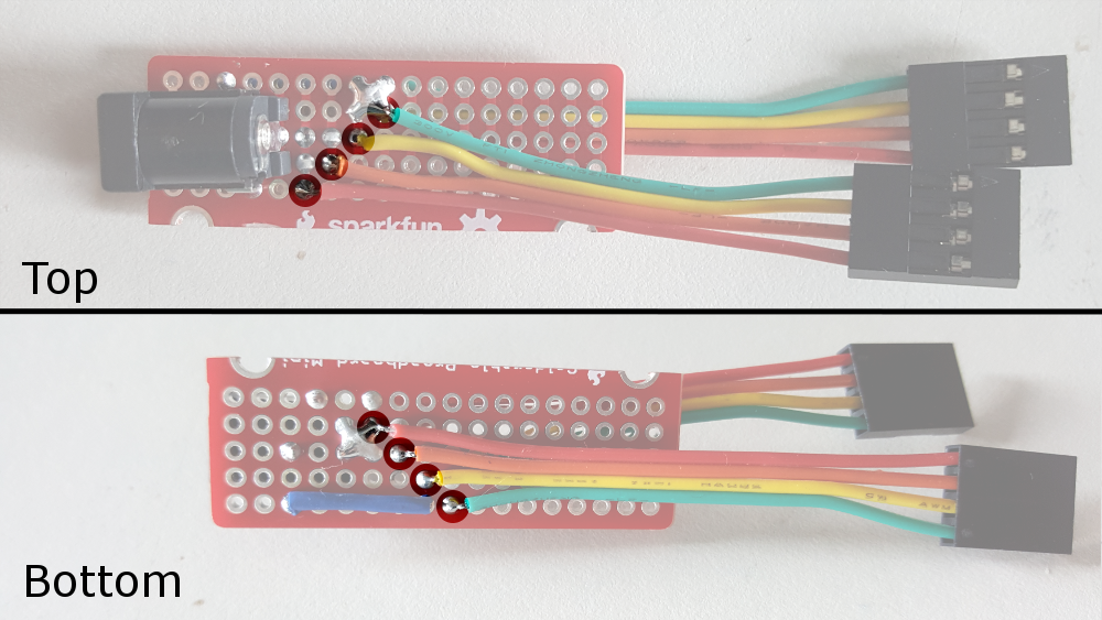
Solder the GND pins together for two of the colors with a solder bridge. Then connect it back to the barrel jack connector an extra wire to the sheath.
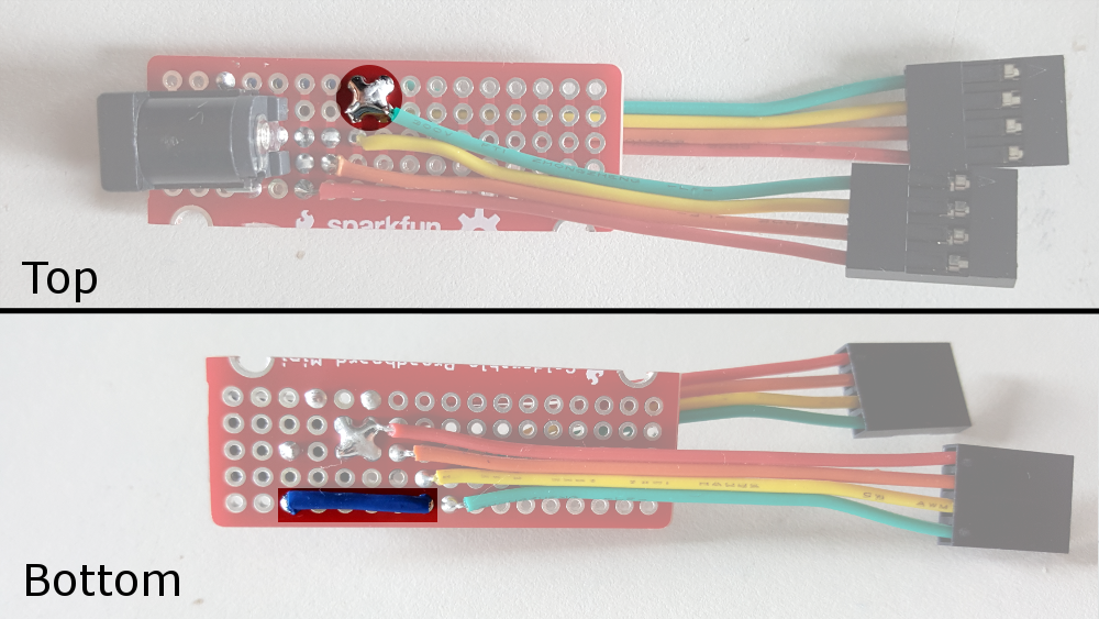
Solder the center pin to the "+12V" pin.
Clean, dry, and test the board with a multimeter, power supply, and the LED strips. Feel free to label the connections with a marker or paint.
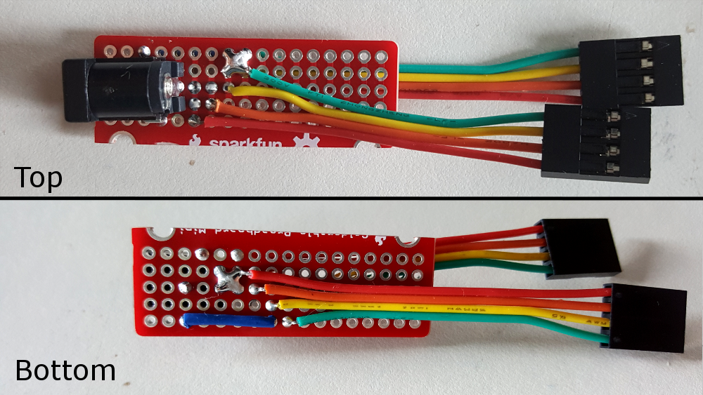
Finally, secure the wires and insulate the connection using hot glue just like the LED strip.
Secure all the jumper wires with electrical tape.
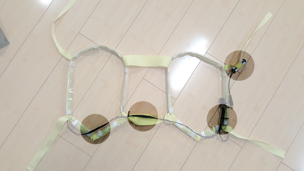
Place the LED strip between the ribbon and vinyl. Make sure to have the LEDs facing out of the clear vinyl. Attach adhesive velcro as highlighted in the image below to hold LED strip down.
Add extra M/F premium jumper wires to extend the LED strip on one side to the breadboard power adapter on the other side. To be consistent I chose to attach the battery and custom adapter on the dancer's left side.
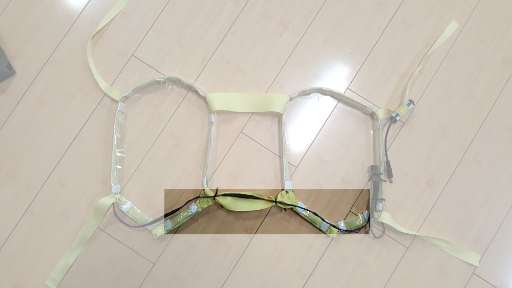
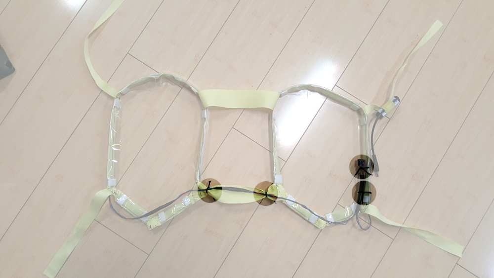
Tie the wires extended on the back and the custom power adapter with string.
The user can then slide the harness on like a backpack, tie the ribbons across the chest and waist, and plug in the battery to test.

Once the first wearable LED dance harness was finished, I repeated the steps until there was enough for each dancer in the troupe. I built a total of 7x units for my students. This required a lot of time and patience.
 |
 |
 |
 |
 |
Over the course of about 2-3 months and balancing my usual work schedule, I was able to finish the project!

Before the rehearsals and performances, I tested the harnesses out under the fabric using a benchtop power supply for about 60 minutes. I then tested it in a studio with the choreography using 9V batteries.
When the time came, my students were excited to test it out for the dress rehearsal. This was a good time to explain how to tie the harness, put on the shirt, and power the LEDs with the barrel jack underneath the button up.
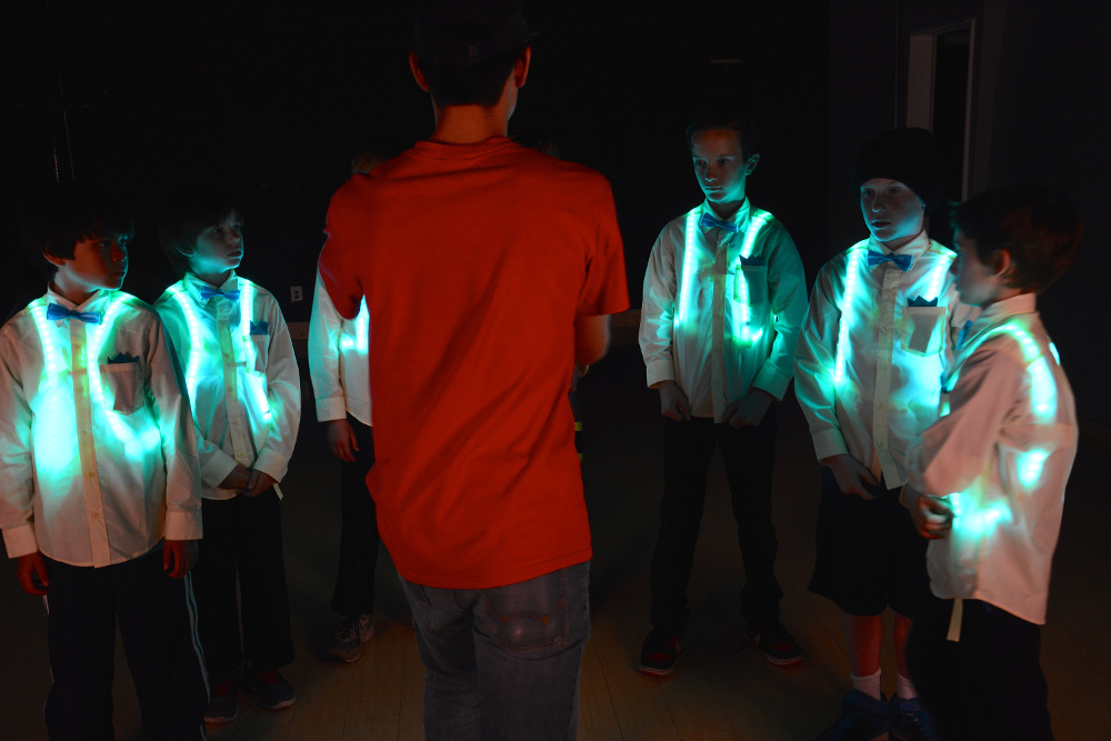
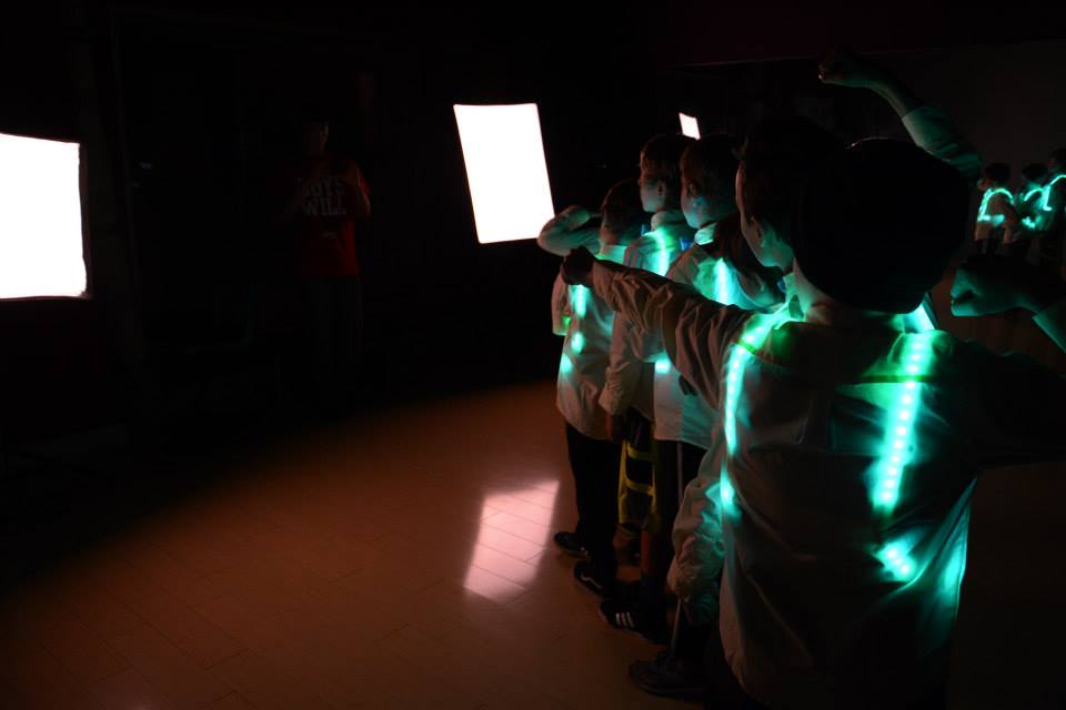
The LED harnesses lasted throughout the dress rehearsal even though they were upside down, side ways, or moving across the floor. There did not appear to be any damage to the circuit. After about an hour, the 9V battery still had power for the show!
 |
 |
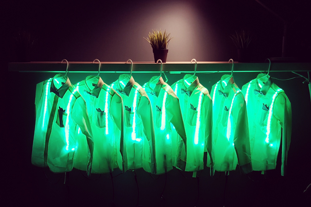
When it came time for the show, I had my handy multimeter, scissors, electrical tape, and backup 9V batteries just in case I needed to troubleshoot. However, everything seemed fine. Here's a picture of them backstage right before going on.
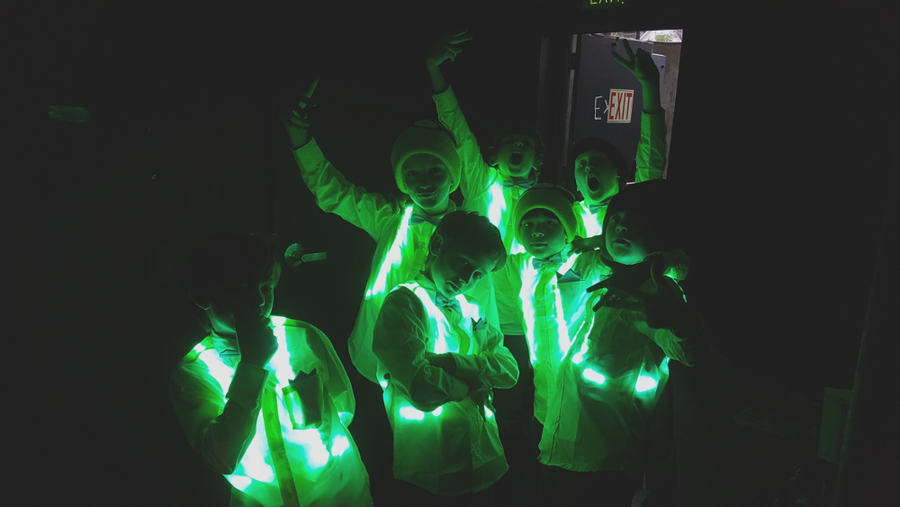
In the end, the performance (which lasted ~1:30-2:00 minutes) ran smoothly without the LED harnesses "breaking" on my bboys. Whew, that was a lot of work!
There's always room for improvement. After the project was completed, I realized that the harness could be built better. Below are a list of possible upgrades and improvements that could be implemented for future builds.
Vest - It was exhausting making about 10x-15x units for each student. In the future, I may just consider buying a vest/harness and adding the parts to the material to save on time and energy.
Quick Release Buckle vs Ribbon Ties - A few of the students had some issues tying the ribbon. Instead of using ribbon ties, a quick release buckle could make it easier
Snaps vs Velcro - The velcro held the LEDs and the vinyl securely. As an alternative, a button tool and metal snap could be used.
Pocket for 9V Battery - With the amount of time I had available, I decided to just tape the battery and cable to the harness and the ribbon tie. A pocket to hold the 9V battery would make it easier to switch out.
Labels - Initially, I did not label the wire colors. After a few months, I forgot about the wire connections on the LED strips, jumper wires, and custom power adapter. I decided to try and revise the project by adding sensors to control the LED straps. It was not until I inspected the connection throughout the harness again that I remembered the simple circuit. Labeling the connection with a marker or paint would have saved some time.
Connectors - The 1x4 female header pins were tedious to strip and solder each wire to the breadboard. Using individual jumper wires might have been easier to connect. However, troubleshooting wires might not be the quickest if a wire becomes loose during a performance. I also noticed that a male header pin broke off one of my student's harness after about 1 year due to wear and tear. In the future, I would probably consider using pigtail connector or polarized PTH connector with cable extensions. I would use switches or transistors rated to handle the current in order to switch between the LED colors.
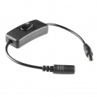
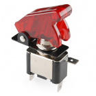
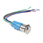
Switch - Plugging in the battery underneath the button up shirt was a little difficult even with the barrel jack. Adding a latching switch after the battery would improve on the design. Below are a few switches that could be used but an enclosure might be needed for the panel mounts switches.
For Mark III, I was able to explore the following option.
Sensor -- Adding a sensor can make the wearable LED dance harness more interactive. It was not until Mark III that I was able to add an acceleroemeter with the wearable LED dance harness. I used the full mini-solderable breadboard, microcontroller, and a MOSFET. For more information, check out the motion controlled wearable LED dance harness.
Need some inspiration for your next e-textiles project? Check out some of these related tutorials:
Or maybe check out these wearable designs from other SparkFunions!
learn.sparkfun.com | CC BY-SA 3.0 | SparkFun Electronics | Niwot, Colorado