Portable DIY Teensy Synth
 Chowdah
Introduction and Video
This is a SparkFun-sponsored project presented by Jeremy Cook. To see more of Jeremy's work, check out his website and his YouTube channel.
Whether via zombies, meteorites, or some techno-apocalypse combo, WE ARE DOOMED!.. at some point. What is certain NOW is that we as a society find the end-of-the-world/disaster concept fascinating, perhaps because there is always a possibility that something could happen. I personally saw the value of having extra supplies on hand after back-to-back hurricanes hit my area in Florida in 2024.
But beyond food and shelter, what are you actually going to do during this (hopefully) temporary situation? For this eventuality — and your entertainment in the meantime — may I present The Teensy Synth for the End of the World. This musical instrument is integrated into a hard case, and comes with built-in speakers, arcade buttons for control, a versatile USB power supply, and the ability to connect to larger systems.
Synth Features and Design
The synth is based around a full octave C3-to-C4 keyboard arrangement of arcade buttons, including five black buttons for sharp/flats. Two buttons above the keyboard enable octave shifting up or down, and four buttons next to those are used to play drum (or other) samples. The system is capable of four-voice polyphony on the keyboard, meaning up to four notes can be played at once, and samples can be played simultaneously. You could even play the keyboard while a second person takes over the drums/samples, potentially enabling cooperation and friendship with neighbors — critical in times of duress.
Built-in speakers enable standalone operation, while a 3.5mm audio jack on the side allows you to connect to external devices for unlimited amplification or even recording. An external USB-B power jack, on/off switch, speaker mute button, and volume control potentiometer round out the build.

The Build
While all hard-case synth-for-the-end-of-the-world designs will be different, below is an overview of how this synth was built. While you can use what's outlined here verbatim, I'd invite you to take these general concepts and run with them, making something amazing and all your own. First, the materials that you will need are listed below:
Materials
Mechanical
- Hard Case: dimensions good, a bit flimsy
- Speakers
- Speaker Grille [3D-printed]
- Buttons support [3D-printed]
- (8) M3 x 12mm screws [screw/nut pack Amazon]
- (8) M3 nuts [screw/nut pack Amazon]
Connectors
- Solid-core hook-up wire kit
- (2) 3.5mm stereo cables
- 3.5mm signal splitter [Amazon]
- Spade connectors
- (2) USB-A to USB-C cable
- (1) USB-A to USB-B cable for charging
- USB-C breakout – horizontal
- Qwiic connector
- Zip-ties
Headers/Breadboard
- Straight, male, single-row headers
- Straight, male, long-centered, single-row headers
- Straight, female, single-row headers
- (2) Screw terminals, 6-pin
- (2) Screw terminals, 16-pin
- (2) Screw terminals, 2-pin
- Solderable breadboard
Buttons, Switches, External Connectors
- Bulkhead 3.5mm connector
- Bulkhead USB-B/USB-A connector
- Toggle Switch & Cover
- 10k potentiometer
- (8) White arcade buttons
- (5) Black arcade buttons
- (2) Yellow arcade buttons
- (2) Green arcade buttons
- (2) Blue arcade buttons
- (1) SPST momentary button with LED
Electronics
Main Board Construction


The heart of this build is the Teensy 4.1, Audio Shield, and Speaker Amp, all of which are connected together via a solderable breadboard setup shown above. The synth’s internal connections are outlined in the schematic below, and one set of rails provides 5V and GND, while the other provides 3V3 and GND. Refer to the video for more insight on how this translates from schematic to the real world.
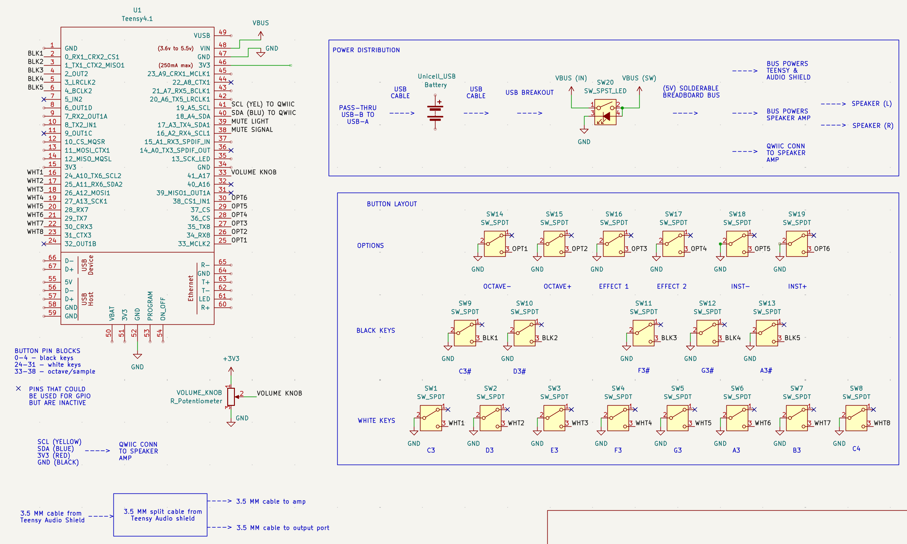
As shown in the video, the Teensy 4.1 is soldered with long centered headers, while the solderable breadboard, along with the Audio Shield, use female headers. This allows for quick attachment and removal as needed. Snap the male headers to length, and clip the female headers to fit on the Audio Shield.

Cut the top of your box as shown in the image and in the video, using a 1 1/8 inch hole saw for the buttons and a 2 inch hole saw for the speakers. DXF/PDFs of the layout are found here. You can use this as a template if you have a large enough printer and/or laser cutter available, but DO NOT laser directly on the case. Drill holes in the side to suit your side interface implements, roughly centered in the vertical orientation.

Populate and Connect
Insert each top arcade button, optionally using the 3D-printed support inside if more rigidity is needed. Remove, then reinsert, microswitches to clear the holes. Link each button’s common pin together using wire and spade connectors, then run the final wire to ground. Link each button to its own individual lead/spade connector, and attach to the corresponding Teensy GPIO via the main board. The input is pulled low when pushed. For organization, I used black wires for each black button, white wires for each white button, and green for ground. Zip-ties are recommended to keep things organized.


Connect the speakers and 3D-printed grill with M3 bolts/nuts. Solder wires onto each speaker’s positive and ground pin to be connected to the I2S amplifier. Ensure all wires are long enough to accommodate the box lid opening and closing, and connect to the appropriate pins on the main board and amplifier via their screw terminals. For the side implements, solder leads to the potentiometer, connecting one side to ground, the other to +3.3V, and the middle to analog pin 17. This acts as a voltage divider and volume knob. Solder leads to the SPST speaker mute button, along with the LED pin if it has one. Connect the switch common and LED negative to GND (I used the screw terminal on the amplifier for GND). Connect the switch NO pin to Teensy GPIO 16 as a mute input, and LED positive to Teensy GPIO 17 to control the light.

Solder wires to VBUS and GND on the USB-C breakout, and connect these to the + and GND pins respectively to the main power switch. Connect the switch’s light icon pin to the +5V rail on the solderable breadboard, and connect the GND pin to the GND rail on the board. Connect the amplifier’s VIN and GND to the main board’s +5V and GND. Plug in the Qwiic connector to the amp and connect leads to SDA, SCL, GND, and +3.3V on the main board as outlined in the schematic. Connect the speakers to the appropriate left/right screw terminals. Connect the charge port of your USB battery pack to the USB-B to USB-A pass-through via a USB-C to USB-A cable. Connect the USB-A output from the battery pack to the switch breakout via a USB-A to USB-C cable. Depending on the battery setup, other cables may be needed/used. Run the 3.5mm signal splitter input to the Teensy Audio shield’s stereo jack. Connect one side to the speaker amp and the other to the audio pass-through using the two 3.5mm stereo cables.
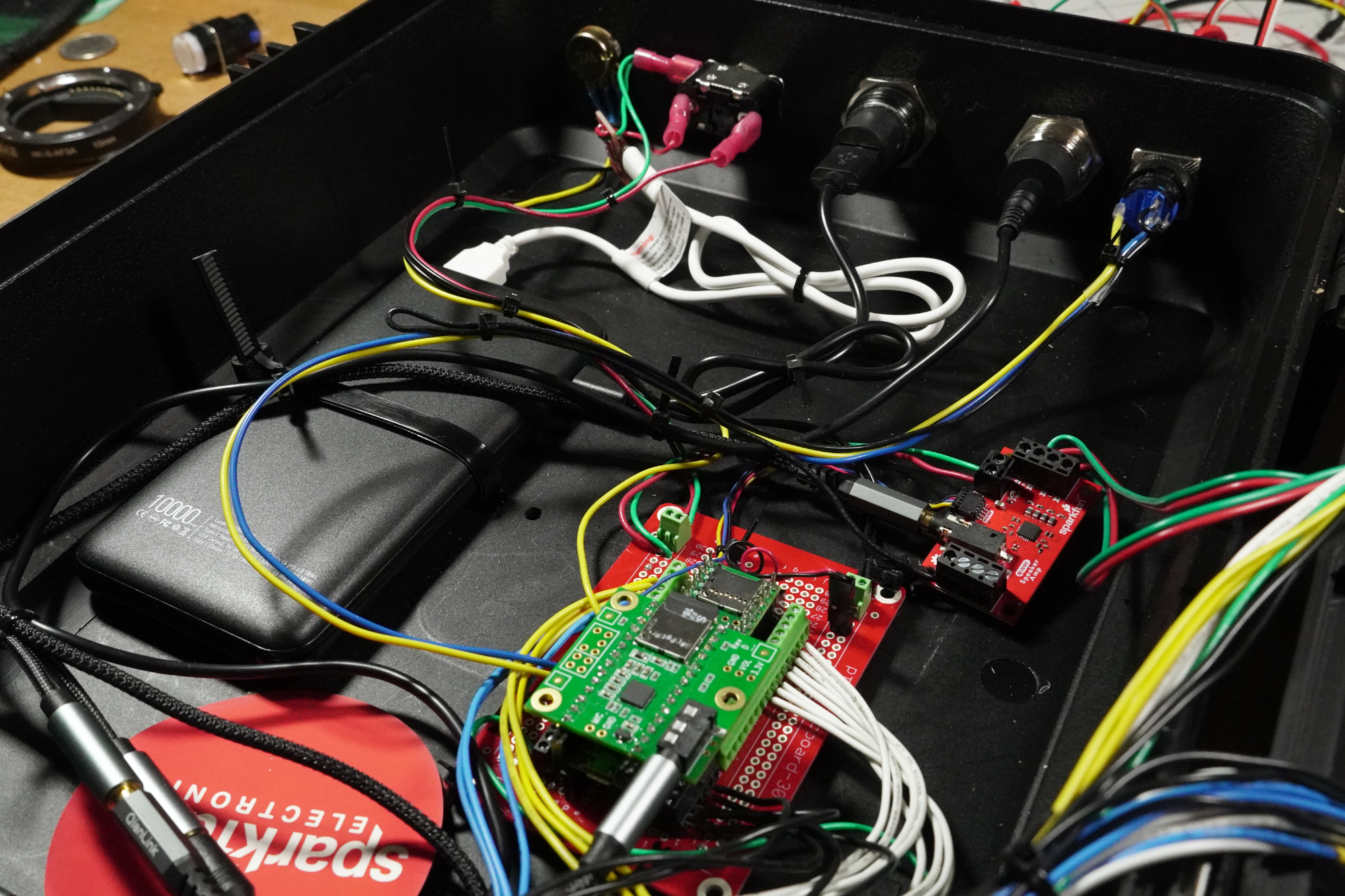

Once you’re satisfied that connections are in place and that the box can open and close without issue, drill holes in the bottom of the box and feed zip-ties through to strap down the main board, amplifier, and battery pack. Use more zip-ties to straighten out the wiring as expedient.
Programming
Code for the synth is found here on GitHub. Load this onto your Teensy 4.1, as outlined in this Getting Started with the Teensy article. Additionally, transfer clips found in the samples directory onto a Micro-SD card for playback, and insert the card into the Audio Shield. If everything was done properly, you now have a working arcade synth — ready for entertainment and music creation in any situation!
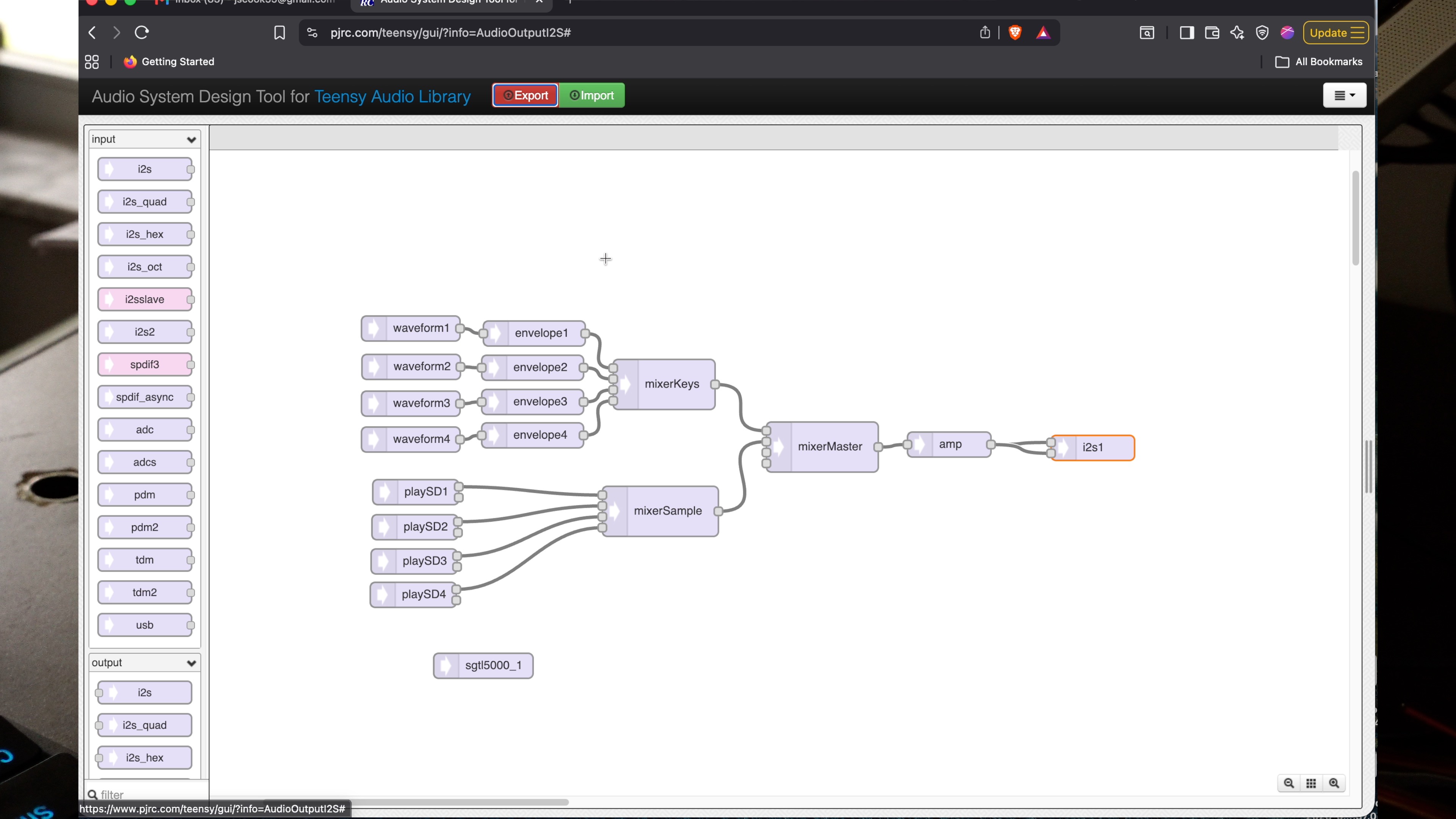

If you want to change the samples around, save new clips at a 44.1 kHz sample rate and 16 bits per sample with the exact names as are on the originals. Mono was appropriate for this application, though the Teensy has no problem handling stereo signals (and beyond) when needed. I used Audacity to transform clips into the correct format, which is a great (and free) tool for this sort of job.
Play!
Depending on your USB pack, you may first have to press a button on the side to initialize output. Close the box and flip the main power switch, and the mute button/light will illuminate to tell you that it’s ready to go. From there... just start pushing buttons. The synth is designed to be self-explanatory — no one needs more stress when the world is ending. After a few seconds of banging around, you should have things figured out.
When you’re ready to go into stealth mode, press the speaker mute button to turn off the external sound and plug a set of headphones into the aux jack. With headphones on, you can play for just yourself.
Alternatively, if you want to GO BIG, plug it into an external amplifier and crank it up. Or connect a recording device and save your sessions for later. Apply power to the USB-A port to keep it charged up when you’re done, and you have a portable instrument that’s ready to go today… or even if things get crazy tomorrow!
Final Thoughts
I hope this project has helped show off the capabilities of the Teensy 4.1, and inspired you to build something — whether musical, Teensy-based, or entirely different. You can find more of my writing here on SparkFun, along with Techadjacent.io, where I discuss technology, making, and... adjacent subjects, like my double-hurricane experience mentioned earlier! Additional build notes:
First, note that this should be considered a prototype, not a finished product. It's a lot of fun to play, but your results may vary and build at your own risk. If you decide to construct your own, below are a few more tips/tricks/notes that you might keep in mind to increase the chances of success:
- The Leftmost White Switch - may intersect the red power switch – I had to rotate the bottom of the button clockwise to avoid interference
- Use zip-ties and possibly heat-shrink – as strain relief methods
- Feed wires – through hole in USB breakout before connecting as a strain relief
- Rigid Case – While the case that I have is sufficient with the 3D-printed reinforcement fixture, a stronger case would help keep things even steadier during jam sessions. Note that the reinforcement fixture that I ultimately used and listed is an expanded version of what’s shown in the video.
- USB Power Bank - Many USB batteries go to sleep without any current draw, including the one listed. With this particular supply, you have to press a button on its side to wake it. When restarted, it typically resets once after a few seconds. It does not provide power when plugged in and charging. While rare, some power banks can provide power when plugged in, a feature known as pass-through charging.
- Lockable Teensy 4.1 – was used in this project, which was unintentional and shouldn’t affect the build process or functionality versus a standard 4.1 (unless you want to secure your code).