If you've had ideas for a project that depend on the ability to sense different spectra of visible light and react based on those measurements, the ISL29125 breakout board may be just what you need.
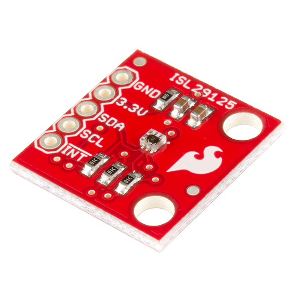
The ISL29125 breakout board, as seen above, in combination with our Arduino library makes it very easy to sense and record the light intensity of the general red, green, and blue spectra of visible light. You can use these color-intensity readings in a variety of projects: log them to find patterns or use them to creatively make control decisions.
This tutorial will show you the hardware side of things -- an overview of the breakout board and how to hook it up to an Arduino. Then we'll cover the firmware/programming half -- how to start getting readings from the sensor as quickly as possible using our library. From there you can continue with your project, or learn about the more advanced uses of this chip. In the last section we'll show you how to configure the chip for more specific needs, as well as how to use interrupt-driven methods to alert you of changes in sensor readings.
The ISL29125 Breakout Board is quite simple in terms of parts. It consists of the sensor chip itself, two decoupling capacitors and 3 pull-up resistors for the I2C and interrupt lines.
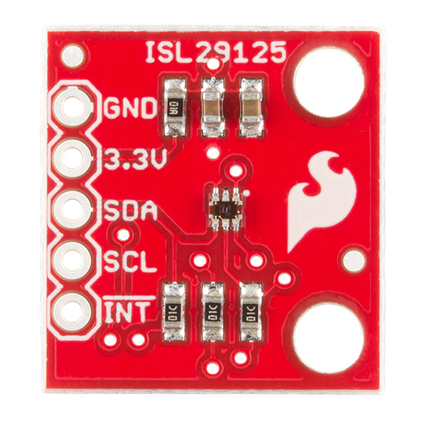
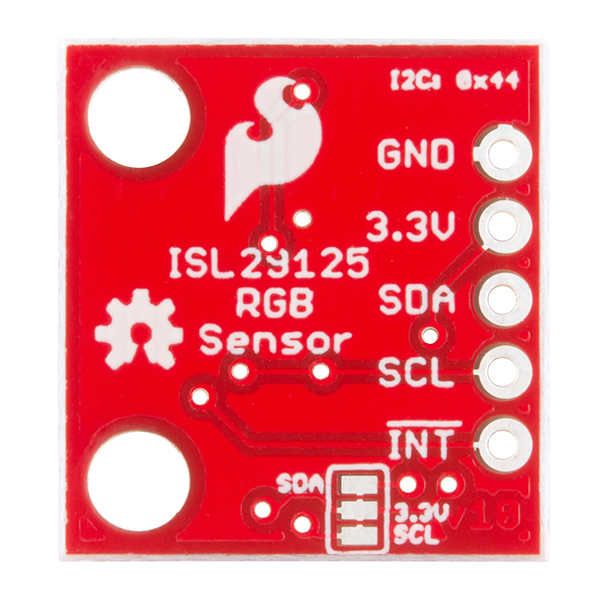
The main header is what allows you to interface with the board. Simply connect power (3.3V) and ground to the designated vias. Connect the I2C lines -- SDA and SCL -- to the corresponding pins on your microcontroller. If desired, you can also connect the !INT pin to a interrupt pin of your microcontroller. Make sure you use 3.3V for power and logic. The chip is not 5V tolerant and will be damaged if you apply 5V to power or any of the inputs. Use a logic level converter if you're controlling the chip with a 5V microcontroller.
If you want to disable the on-board 10kΩ I2C pullup resistors -- in case you want to use those built into your microcontroller or other external pull-ups -- simply cut the two traces between the three pads on the backside of the board. If you decide you want the pull-ups later, you can always solder the pads back together.
Now that you're familiar with the board, let's get it up and running.
Before we dive into the code, we need to connect the Arduino Uno to the ISL29125 breakout board. Connect the 3.3V and GND on the Arduino to the 3.3V pin on the breakout board. Connect SDA on the breakout to A4 on the Uno, SCL to A5 on the Uno. If you're using the Uno or any 5V Arduino, you'll need a logic level converter between SDA/SCL on the breakout and A4/A5 on the Uno. If you don't know how to use the converter, this logic level conversion tutorial explains how.
Now that the hardware is ready, let's move onto the software.
Now that the hardware is set up, you'll need to install the Arduino Library for the ISL29125. Click here to download the library. Or you can grab the most up-to-date version of the code on GitHub.
To install the library unzip and place the library folder in the "libraries" folder in your Arduino sketchbook. For more help installing the library, refer to the Arduino Library Installation Guide.
In the Arduino IDE, go to File > Examples > SparkFun_ISL29125_Arduino_Library > ISL29125Basics. This will load a simple example that will get you quickly reading light intensity levels in the red, green, and blue spectra. Let's dive into the example sketch.
To setup the example we simply declare a sensor object and run a basic initialization function that will communicate with the sensor. The init() fuction will command the ISL29125 to start taking readings for red, green, and blue. In addition to calling RGB_sensor.init(), the setup() function also initiates serial communication so we can send information from the sensor to our Serial Monitor (make sure to set your Serial Monitor to 115200 baud).
language:cpp
// Declare sensor object
SFE_ISL29125 RGB_sensor;

void setup()
{
  // Initialize serial communication
  Serial.begin(115200);

  // Initialize the ISL29125 with simple configuration so it starts sampling
  if (RGB_sensor.init())
  {
    Serial.println("Sensor Initialization Successful\n\r");
  }
}
Now how do we actually acquire those sensor readings? Well that's up next. The sensor readings are stored as 16-bit unsigned integers. Using the library we can call our sensor objects functions readRed(), readGreen(), and readBlue() to get the light intensity readings for red, green, and blue respectively. Each time through loop(), we take these readings, print them to the Serial Monitor, then wait a couple seconds. Here's the code for this functionality:
language:cpp
// Read sensor values for each color and print them to serial monitor
void loop()
{
  // Read sensor values (16 bit integers)
  unsigned int red = RGB_sensor.readRed();
  unsigned int green = RGB_sensor.readGreen();
  unsigned int blue = RGB_sensor.readBlue();

  // Print out readings, change HEX to DEC if you prefer decimal output
  Serial.print("Red: "); Serial.println(red,HEX);
  Serial.print("Green: "); Serial.println(green,HEX);
  Serial.print("Blue: "); Serial.println(blue,HEX);
  Serial.println();
  delay(2000);
}
If you simply want sensor readings to log, view, or use in a further calculation for your project, this is all you really need to know. However, if you'd like to know more about the gritty details of sensor configuration -- or how to trigger a processor interrupt based on a specific sensor reading -- continue to the advanced section.
Going beyond basic readings, the ISL29125 allows you to tailor the configuration of the sensor to custom-fit your application's specific needs. In the library there is a config() function that takes three arguments -- one for each of the sensor's configuration registers. That will be our workhorse for customizing the ISL29125's operation.
Let's take a look at the "ISL29125_interrupts" example, which demonstrates how to configure interrupts. This example is configured in a way that the sensor only reads red values and triggers a processor interrupt when the red sensor reading is above a specified threshold.
Before we can use the interrupts, we have to configure them -- set them up. Within the setup() function, after initializing the sensor as we did in the basic example, we configure the sensor with this function call:
language:cpp
RGB_sensor.config(CFG1_MODE_R | CFG1_10KLUX, CFG2_IR_ADJUST_HIGH, CFG3_R_INT | CFG3_INT_PRST8);
We use the first configuration register -- set with the first argument -- to define the sampling mode. In this case, we only want the sensor to collect data in the red spectrum, so it doesn't waste time sampling for blue and green. The mode we used in the basic example (set up behind the scenes) was CFG1_MODE_RGB, which collects data for all three colors. The mode can be set to any individual color, combination of two colors, or even powerdown and standby modes.
In addition to setting the channels sampled, the first parameter is also used to sets the light intensity. We set the light intensity scale to 10k lux, which is best for normal light levels. There's only one other option for light intensity -- 375 lux -- which is better for very dark environments. This register can also be used to change the sensor readings from 16-bit to 12-bit for less accurate but faster readings. It can even turn the INT pin into an input that triggers data sampling.
The constants you use to set up these registers, as well as additional information about using them can be found in the "SFE_ISL29125.h" file within the library directory. Feel free to take a look at that now or on an as-needed basis.
The second configuration register is solely concerned with IR filtering. Setting it properly, involves a calibration process with measurements taken with specified types of lights. The datasheet explains this process on pages 13 and 14, while more information on the register itself is on pages 10 and 11. If you're not sure what to set for this register, start with the value CFG_DEFAULT or CFG2_IR_ADJUST_HIGH. In this example we used the latter and it worked great for the office environment here at SparkFun. If neither of those seem to work for your application great, experiment with values, or follow the datasheet's calibration process.
The third configuration register is all about interrupts and can be left to default if you're not using them. In this example we set CFG3_R_INT, which tells the sensor to trigger interrupts based on red values being read by the sensor. You could also set this to green, blue or off, but there is no way to trigger on multiple colors at the same time.
Now that interrupts are on, when do they actually trigger? Well that has to do with thresholds, let's look at this next line of code within the setup() function of our example.
language:cpp
RGB_sensor.setUpperThreshold(0x0B00);
//RGB_sensor.setLowerThreshold(0x0300);
For an interrupt to be triggered, the red sensor value either has to be above the upper threshold or below the lower threshold. We set these two thresholds with the above functions but in this example we only use the upper one. By default the upper threshold is 0xFFFF -- the highest a sensor reading could be -- and the low threshold defaults to 0x0000 -- the lowest a reading could be.
So, will an interrupt trigger if the sensor reading for red exceeds 0x0B00 once? Well, if we configured the third register with the option CFG3_INT_PRST1, then the answer would be yes. But in this example we used CFG3_INT_PRST8, which means the sensor has to have eight consecutive readings that exceed the set threshold value before an interrupt triggers. This helps prevent false positives and allows us to see the larger picture without worrying about sudden fluctuations. Feel free to change the interrupt persist amount to what best suits your application. It can be set to 1, 2, 4, or 8.
Now that we've learned more specifics for configuring the sensor, let's dive a bit further into the example. How does our Arduino actually use these interrupts coming from the sensor?
The INT pin of the sensor is active-low. This means it remains at 3.3V until an interrupt condition is met, at which point it goes LOW (ground). In our example, we connect this pin to digital pin 2 -- one of Arduino's external interrupt pins (using a logic level converter if needed as we did with the I2C lines).
In our setup(), we connect this interrupt to a function, also known as an interrupt service routine (ISR). The following code performs this:
language:cpp
attachInterrupt(0, increment, FALLING);
This makes interrupt 0, which is digital pin 2 on the Uno, call the increment() function when the interrupt pin transitions from HIGH to LOW (falling edge). So whenever the sensor reads the red value to be above 0x0B00 for eight consecutive samples, the interrupt line drops, and the increment() function is called in our code. This function simply increments a global variable i as seen below:
language:cpp
void increment()
{
    i++;
}
Each time through our loop() we check to see if i is different from our recorded lasti variable. If so, we print the interrupt number, the red sensor reading, and the amount of milliseconds since the last interrupt. Finally, we set lasti = i so we don't enter the if statement again until the next interrupt. We also call the sensor's object function readStatus() which clears the interrupt flag and allows another interrupt to be triggered in the future.
Here's the full loop() if you want to take a closer look at the details:
language:cpp
// Continuously check if an interrupt occured
// If so, print out interrupt #, sensor reading for red light, and time since last interrupt to serial monitor
void loop()
{
  static unsigned int lasti = 0; // Stores the number of the last interrupt
  static unsigned long ms = millis(); // Used to calculate the time between interrupts
  uint16_t red_value = 0; // Stores sensor reading for red light intensity
  uint8_t flags = 0; // Stores status flags read from the sensor

  // Check if an interrupt has occured, if so, enter the if block
  if (lasti != i)
  {
    // Read the detected light intensity of the red visible spectrum
    red_value = RGB_sensor.readRed();

    // Print out the interrupt # and sensor reading
    Serial.print("Interrupt #: ");
    Serial.println(i);
    Serial.print("Red Sensor Value (HEX): ");
    Serial.println(red_value, HEX);
    // Print out the # of milliseconds since the last interrupt
    Serial.print("Milliseconds since last interrupt: ");
    Serial.println(millis() - ms);
    Serial.println();
    ms = millis(); // Reset ms so we can start counting milliseconds up to the next interrupt

    // Set lasti to i, so that this if statement is not entered again until another interrupt is triggered
    lasti = i;

    // Read and clear the status flags including the interrupt triggered flag
    // This must be done otherwise another interrupt from the sensor can not be triggered
    flags = RGB_sensor.readStatus();

    // If you desire to see the reported status of the chip, uncomment the line below
    //checkSensorStatus(flags);
  }
}
Interrupts are quite useful when you want to monitor for a change in light level but don't know when it might happen. Remember to modify the configuration registers and the interrupt thresholds to what's suitable for your application.
By now you've become familiar with the the ISL29125 sensor, the breakout board hardware, how to acquire sensor readings, and how to implement advanced configurations and interrupts. Enjoy experimenting and seeing what creative uses you find for this sensor. Always feel free to share your projects and/or feedback with us here at SparkFun!
learn.sparkfun.com | CC BY-SA 3.0 | SparkFun Electronics | Niwot, Colorado