In this tutorial, we'll cover DMX512 (Digital Multiplex with 512 pieces of information). Originally intended as a way to standardize communication among lighting dimmers, DMX512 has been adapted to control a variety of stage lighting and effects such as intelligent lights, gobos, lasers, and fog machines. DMX512 is even used in many architectural lighting scenarios (I'm looking at you Las Vegas). In this tutorial, we'll go over what there is to know about how and when to implement DMX.
DMX512 was created in 1986 by an engineering commission for USITT (United States Institute for Theater Technology) as a way to control dimming channels on lights. In 1998, the ESTA began work in getting DMX to the point where it could be approved by ANSI and in 2004, DMX-512A was ANSI approved as the "Asynchronous Serial Digital Data Transmission Standard for Controlling Lighting Equipment and Accessories."
Check out this tutorial on serial communication if you aren't familiar with serial communication.
DMX512 is typically employed over relatively long distances due to the distance between the lighting booth and stage. The further a signal is sent, the longer distance you have available to pick up stray electromagnetic interference from the surrounding area. Combine this with the fact that DMX is usually used in electrically noisy environments and we have to settle on a solution that is relatively noise free, so DMX employs RS-485.
Signals like this are interpreted by reading the difference between one wire with the data (D+), and another wire with the inverse of the data (D-). Since we are reading the difference, we call this a differential signal. Differential signals like RS485 pick up noise almost equally along the two signal lines, this keeps the difference between the two signals the same. Since we read the difference between the two signals, it's easy to communicate over long distances (The DMX standard recommends a maximum run of a thousand feet, although RS-485 is rated for 4,000 feet).
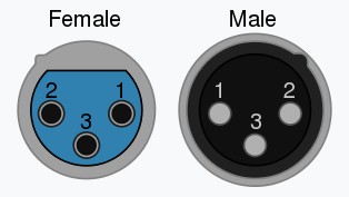
DMX data is typically transferred over an XLR-5 cable, although occasionally, DMX capable XLR-3 cables are also used. RS-485 only requires 3 lines, ground, Data+, and Data-; and in many applications, this is all that was used. However, an additional pair of data lines was added to allow for future growth, requiring the XLR-5 cable. These connectors and their pinouts are shown below.
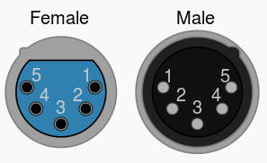
| Pin | XLR-3 | XLR-5 |
|---|---|---|
| 1 | Common | Common |
| 2 | Data 1 - | Data 1 - |
| 3 | Data 1 + | Data 1 + |
| 4 | N/A | Data 2 - |
| 5 | N/A | Data 2 + |
An issue that arises with the communication over distance is that DMX devices are usually powered far away from each other. These distances this can result in ground loops; differences in voltage between the ground potentials of two devices which, if high enough, results in current flow between devices. Due to this distance, the DMX512 standard also calls for opto-isolation between the microcontroller and DMX portions of the circuit on a DMX fixture.
It is also wise to fit a 120Ω termination resistor between the two data lines at the extreme end of the chain of DMX devices to prevent signal reflection. Some devices have a switch, some will suggest you plug in an XLR cable with a terminating resistor attached, while others simply won't have one at all. An unterminated DMX line can cause flickering in your whole Universe, so be sure the line is terminated.
DMX data is asynchronous serial data sent at 250 kbit/s with 2 stop bits and no parity. This means that each clock pulse or bit sent takes 4 µs. The packet is structured beginning with a long BREAK where all data sent is low. This is followed by a Mark After Break or MAB, which is a short period high. There is then a Start Code (SC), consisting of an 11 bit serial frame (1 low bit, the 8 bit data byte, and 2 high bits) in which the data sent is 0x00. The Start Code can also contain different data to signify what type of DMX data is contained within the packet; 0x17 signifies a text packet, 0xCC for a Remote Device Management packet (more on this later), 0xCF is a system information packet, all sorts of start codes are used to signify different types of data. The Start Code is then followed by up to 512 frames of the same structure, each called a SLOT, containing all of the DMX data (RGB values, CMY values, servo position, fog machine pressure, etc...). There is an optional Mark Time Between Frames, (MTBF) which can be up to a second high between each frame. Once the data frames have finished sending, there is another Mark Time Between Packets (MTBP) of up to a second. However, these are rarely used to maintain frame rate. The table below shows the timings and common abbreviations of each of these parts of a DMX packet.
| Packet | Abbr. | Clock Pulses | Timing |
|---|---|---|---|
| Break | BREAK | 22 | 88 µs |
| Mark After Break | MAB | 2 | 8 µs |
| Start Code | SC | 11 | 44 µs |
| Mark Time Between Frames | MTBF | X | 0-1 s |
| Slot | SLOT | 11 | 44 µs |
| Mark Time Between Packets | MTBP | X | 0-1 s |
| Full DMX512 Packet | N/A | 5667 | 23 ms |
Note the time it takes for a full DMX packet to be transmitted (23 ms). Inverting this gives us a maximum frame rate of 44 Hz.
The previously discussed DMX packet is then sent down the string of devices, but how should a device know which slot of the packet it needs to listen to? DMX fixtures usually have a DIP switch located somewhere to select the starting data slot to listen to, then the fixture will listen for it's fixed number of slots. For example, a simple RGB dimmer will take up 3 slots, one for each color, so if we set the starting slot to 12, it will listen to the data on slots 12, 13, and 14. DMX fixtures should increment their slot counter on the second stop bit, so when the next frame begins, the microprocessor will know which slot the data should be in. The counter should then reset every time a break and mark are detected. This means that a DMX packet doesn't have to have all 512 data slots, as the counter can reset at variable intervals. However, this limits the amount of fixtures occupying a single Universe depending on how many slots each fixture needs.
Remote Device Management, or RDM for short is a way to use DMX to get information back about lighting fixtures. The protocol sends out a DMX512 packet with an RDM start code (0xCC) followed by a unique ID of the fixture it is attempting to communicate with. The controller will then release the data lines, and wait for a response. After a certain amount of time, the controller will assume it's failed and may try again. RDM is a great way to find out exactly what each fixture is capable of if you're just plugging into an unknown Universe.
Hopefully this guide has allowed you to get your super cool and wacky light fixture communicating over DMX, making it easy for anyone to control it without having to tediously code their own lighting patterns. Check out these implementations of DMX if you're looking for a little inspiration.
Need some inspiration for your next project? Check out some of this related tutorial.
learn.sparkfun.com | CC BY-SA 3.0 | SparkFun Electronics | Niwot, Colorado