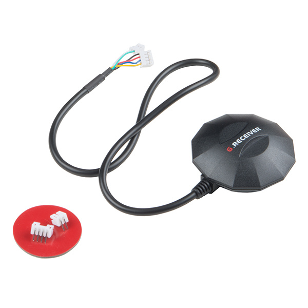
The GPS Mouse is a combination GPS and compass in a self contained module perfect for UAV and autonomous vehicle enthusiasts. The GP-808G housed inside is a highly sensitive GPS module that can accurately provide position, velocity, and time readings. This module is highly accurate, easy to use, requires almost no set-up time, and is very easy to embed into your projects!
This 72-channel GPS receiver, that supports a standard NMEA-0183 and uBlox 8 protocol, has low power consumption of 40mA @ 3.3V-5.0V, GPS/QZSS/GLONASS support, and -167dBm tracking sensitivity. The GP-808G has been terminated with two JST connectors (one 4-pin and one 2-pin) and includes their mating counterparts. The GPS Mouse has been a popular go-to GPS option for many of the entrants in our annual Autonomous Vehicle Competition (AVC) with great results!
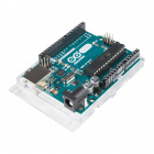
To follow along with this guide all you need is an Arduino compatible microcontroller, such as an Arduino Uno or SparkFun Redboard, a breadboard, and some jumper wires. This example uses a SparkFun RedBoard.
If you have never worked with GPS before, have a look at our GPS Basics tutorial.
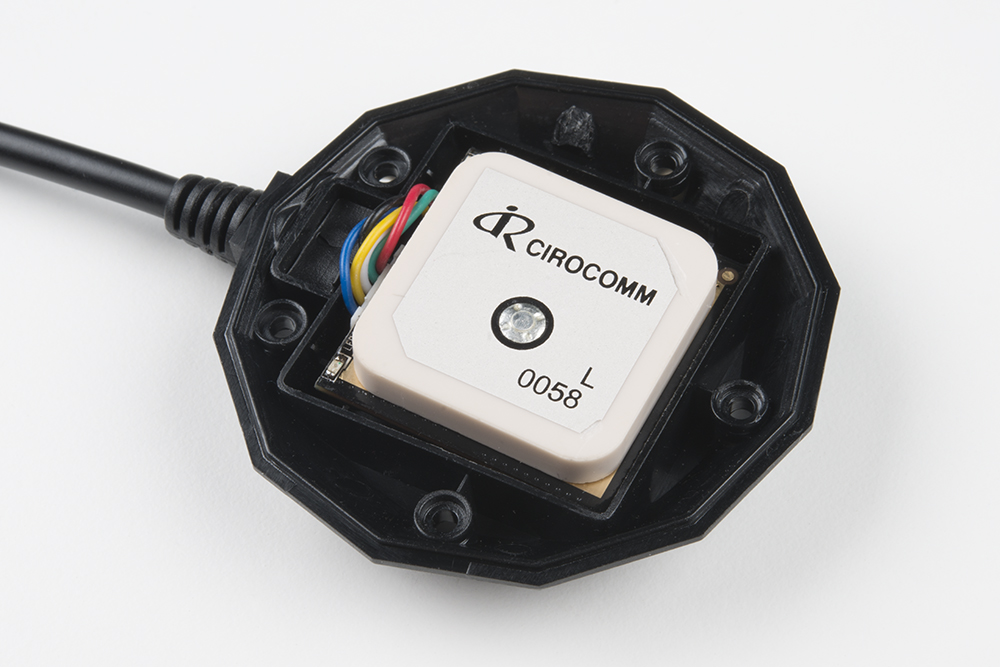
Let's go over the GPS Mouse in detail.
Inside the enclosure, you'll find a normal looking GPS module with a few extra bits. On the underside, you'll find a backup battery for warm and hot starts as well as the onboard QMC-5883 Magnetometer.
The pin out for the GPS connectors are as follows:
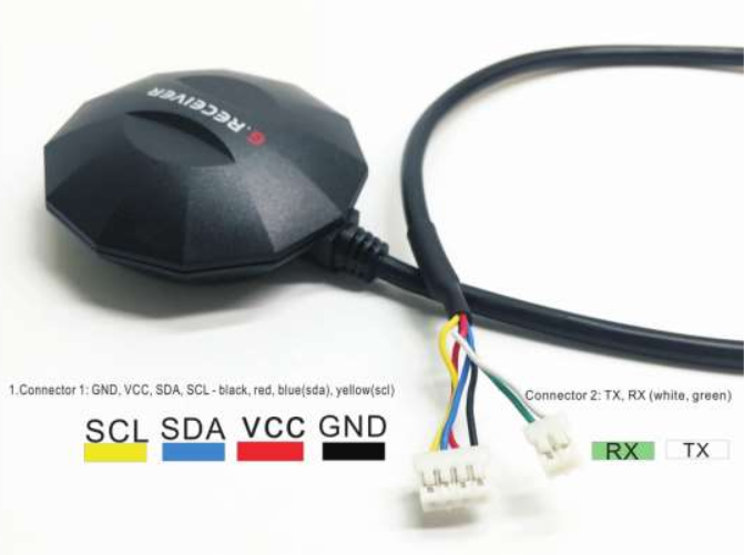
The I2C lines are for factory programming of the module. No register data is available in the device's datasheet. All communication with the device in this guide occurs over serial.
This GPS module is designed for pro makers who wish to have a GPS module attach to their custom PCB or hand-built prototype. However, you can easily connect the GPS unit to a breadboard with the included connectors and wire it up to a microcontroller of your choice. For a secure connection, you can also solder the wires to a custom PCB.
To connect the module to a breadboard, insert the 4-pin and 2-pin female JST connectors.
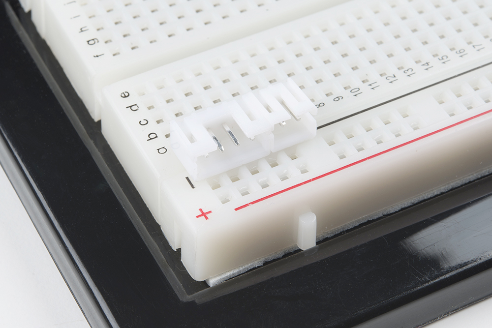
Connect the GPS male JST connectors into the female connectors. You can now wire the GPS Mouse to the microcontroller using jumper wires.

For a more robust connection, you can also snip the JST connectors off and solder the bare wire ends to straight male headers or any other connector of your choosing.
The connections from the GPS Mouse to the SparkFun RedBoard used for this example are as follows:
| GPS Mouse Pin | SparkFun RedBoard Pin |
|---|---|
| TX (White) | Digital Pin 4 |
| RX (Green) | Digital Pin 3 |
| GND (Black) | Ground (GND) |
| VCC (Red) | Power (5V) |
Now that we have everything connected, lets get started with some code. Before we start writing code though, we do need to install a library to parse the GPS messages. If you haven't downloaded Arduino libraries before or you just need a quick refresh, check out our tutorial on installing Arduino libraries. The library we need is called TinyGPSPlus from Mikal Hart. You can download and install the library from the link below.
Now that we have the library installed, let's look at the code. In Arduino, open the example sketch by clicking File -> Examples -> TinyGPSPlus-version -> DeviceExample.
In the example, you will need to change one line of code. Change the variable GPSBaud to 9600 with the following line:
language:c
static const uint32_t GPSBaud = 9600;
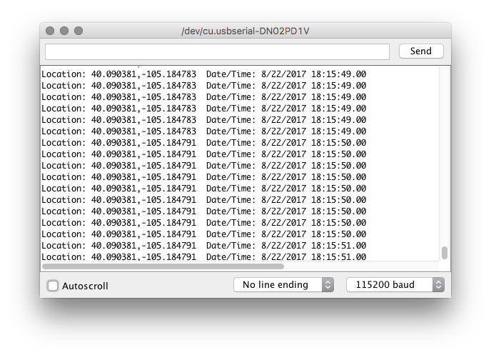
The rest of the example sketch should work as is. Upload the sketch to your Arduino board. Once uploaded, open the Serial Monitor set to 115200 baud. You should see GPS serial data streaming by. If the location says INVALID, wait several minutes for the GPS unit to get a lock. If you do not see GPS data after several minutes, see the troubleshooting section below.
Note: While the GPS uses 9600 baud on the software serial pins, the serial UART for the serial monitor is set to 115200 baud.
If you're testing your GPS inside, make sure you're next to a window. One of the problems with GPS is that radio waves have a difficult time passing through roofs and ceilings. So the closer the GPS is to being outside, the better. If you still aren't reading from enough satellites to get a position fix, try pointing the GPS antenna in a different direction.
If you see this message print to the Serial Monitor: No GPS detected: check wiring. do just that. Check your wiring and make sure that you have the correct pins connected to the GPS connector.
If you place the GPS mouse in a dark room, you will be able to see the onboard GPS LEDs blinking inside the enclosure. If you see a green LED, that means the GPS unit is getting power. If you see a blinking blue LED, the GPS unit has a lock. If you see the blinking blue LED and aren't getting any serial data printed to the Serial Terminal, check your wiring and check that you have the correct pins defined at the top of your code.
For more information about the GPS Mouse, check out the links below:
Now that you've got the GPS Mouse up and running, what project are you going to use it for? Need a little inspiration? Check out some of these tutorials!
learn.sparkfun.com | CC BY-SA 3.0 | SparkFun Electronics | Niwot, Colorado