Experimental Products: SparkX products are rapidly produced to bring you the most cutting edge technology as it becomes available. These products are tested but come with no guarantees. Live technical support is not available for SparkX products.
The GeoFence is designed to make it easy for you to add geofencing capabilities to your next project! If you're not familiar with the idea of a geofence, no worries, let's go to Google for the definition:
...a virtual geographic boundary, defined by GPS or RFID technology, that enables software to trigger a response when a mobile device enters or leaves a particular area...
Okay, so basically it's a big invisible boundary that's enforced using GPS technology. What's so great about that? Well, some people use them for asset tracking or fleet management. GPS geofences are a great way of making sure that a certain item (or vehicle) is in the right place at the right time. But there are also fun and creative applications for geofencing, such as Mikal Hart's Reverse Geocache™ or our own Robert Cowan's NCWP Scavenger Box.
Since geofencing requires a controller to be constantly checking its own position against a table of locations, it can take up a lot of cycles in your project. To solve this problem, we built this dedicated board.
Simply use the software to define your geofence boundaries and the board will output a logic high signal on any of four zone status pins when the corresponding boundaries are breached!
This guide will help you get up and running with the GeoFence board and software so you can define your own GPS boundaries and start using geofences in your future projects!
To follow along with this tutorial, you will need the following items:
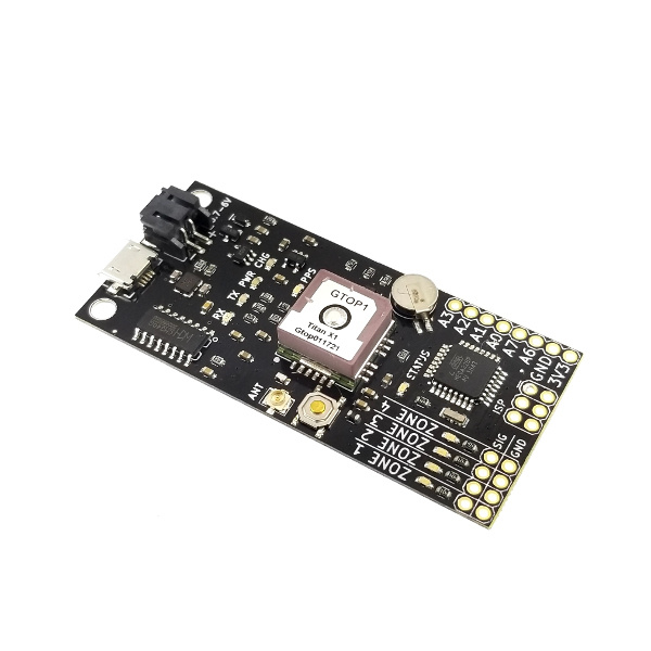
Let's get familiar with the hardware on the GeoFence. We'll break it down into two categories: The connectors and the LED indicators.
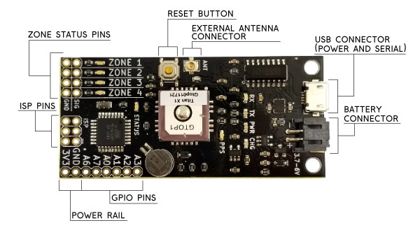
These pins each correspond to a numbered boundary in the software. The row of pins labeled SIG are the signal pins and the row beside them are ground pins. Whenever the board is outside of a defined zone, that zone's pin will remain logic LOW. As long as the board is inside of a defined zone, that zone's pin will remain logic HIGH.
This button is tied to the reset line on the microcontroller and will restart the board.
The Titan X1 GPS module has a good built-in antenna but if you embed this board into an enclosure where the antenna can't pick up anymore satellites you can connect a 3V external antenna to this U.FL connector (we sell a U.FL to SMA cable if you need one). The GPS module will automatically select an external antenna if one is present.
The Micro-B connector is used to load zone configurations onto the board as well as to provide power for charging a connected lithium ion battery. Since the on-board ATmega328 is carrying the Arduino bootloader, you can also use this USB connector to push new firmware to the board. Select the Arduino Pro Mini with 3.3V/8MHz when loading new firmware.
The GeoFence has a built-in battery charger and voltage regulator so you can easily power it on the go. Any of our single-cell lithium ion batteries will work but I personally like the 1Ah battery because it's about the same size as the board.
These are excess pins broken out from the ATmega328P that you can use if you write your own firmware. The production firmware for the GeoFence uses the A0 pin as the System Status pin which goes to logic HIGH when the system has a valid lock. This pin makes it possible for outside systems to know whether the zone status pins are showing the most up-to-date information.
The 3V3 and GND connections here allow the board to be powered from an outside regulated 3.3V source. Because this pin is connected directly to the 3.3V rail on the board, it will also source 3.3V whenever a battery is connected or the board is plugged into USB power.
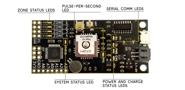
These LEDs reflect the state of the zone status pins. They come in handy for testing as you can tell at a glance whether or not the board is in a particular zone boundary.
This LED is connected to the PPS (Pulse Per Second) output of the Titan X1 GPS module. The PPS output goes logic HIGH for a short duration once per second. This timing signal is a good secondary indicator for whether your GPS module is functioning correctly.
These are the same lights that you would find on most Arduino boards. They're connected to the serial communication lines between the USB-Serial bridge and the ATmega328. They're labeled with respect to the microcontroller so RX flashes when the board is receiving data and the TX light flashes when the board is sending data.
The PWR LED will stay lit as long as the board is powered. The CHG LED represents the charging status of the lithium ion battery if one is connected. If there's no battery connected, this LED will be off. If there is a battery connected, the LED will remain on as long as it's charging. When the battery is full, the LED will turn off again indicating that charging is complete.
This LED will display one of three system status alerts. If the LED is blinking, then the board is running but the GPS module is waiting to get a lock. If the LED is solid then the GPS has a lock, valid data is coming in and the board is checking zones. If the status LED stays off, there are no zones programmed into the board and no zone tests will be performed.
The GeoFence Software is built and distributed using the Electron framework. We've made an executable installer for Windows 64-bit systems, so for the purposes of this guide, we'll assume you're running Windows. At the end of this section I'll briefly discuss how to get GeoFence running on different environments.
Before we get into the user interface, let's download and install the software. First of all, you'll need to download the executable installer:
When you launch the installer it will ask if you're sure you want to install GeoFence. Click "yes" to install the software which will auto-launch as soon as it's finished. Now you should see something that looks like this:
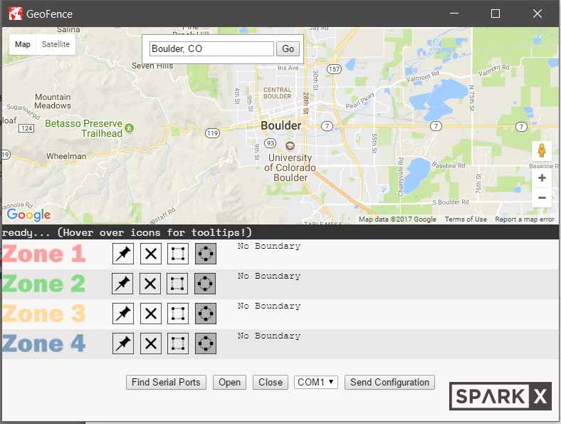
As you can see, GeoFence leverages the Google Maps API to make selecting geographic regions easier. If you can't see the map, you may not be connected to the internet. The GeoFence Software requires an active internet connection in order to retrieve maps from the Google Maps API. It will start in Boulder, CO by default but you can type any location into the search bar at the top to travel to that location.
There are four zones in the software corresponding to the four zones on the board. Each zone is color coded so that the boundaries will be easily distinguishable on the map. In the next section, we'll go over how to create zone boundaries and load them on your GeoFence board but for now, let's just break down the user interface:
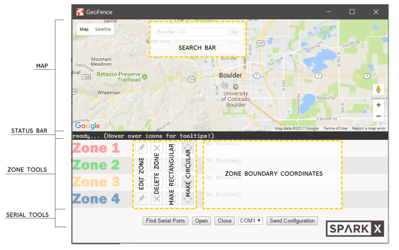
The map is where you can draw all of your zone boundaries. It's powered by Google Maps, so it should always be accurate and up-to-date.
If you want to jump to a location on the map, you can use the search bar to get there. Type a zip code, the name of a city or even a business name and press "Go" to jump to that location. the zoom level of the map is not adjusted when making a jump so you may need to zoom in to find your destination.
This is where the application will notify you of what's going on.
The zone tools are how you'll be defining your zone boundaries. There are four zones with four functions each:
Whenever you create a zone boundary on the map, the coordinates for that boundary will be displayed here. This is the data that will be sent to the board.
These controls are all for manipulating the serial port. From here you can scan for active serial ports, open a connection, close a connection and push your zone definitions to the GeoFence hardware.
Because the GeoFence software is written essentially like a webpage and uses Node.js modules to interact with your computer's serial ports, it's totally cross-platform compatible. In order to run GeoFence from source code, you just need to install node.js, Electron and the serialport package for node. Once those things are all installed, open a terminal and navigate to the folder where you've downloaded the GeoFence source code then run "electron ."
If you find that the serial port doesn't work correctly, you may need to re-install it using the instructions found here or rebuild the serialport module to get it to work properly on your system. The utility that we used to package the app for Windows machines will also generate packages for Linux and OSX, so if you have experience with electron-builder and have successfully tested the serial module under one of these environments, please feel free to build an executable for your platform and send us a pull request!
Now let's define our first set of zones and send them to our GeoFence hardware! First, launch the GeoFence app, you should see something like this:
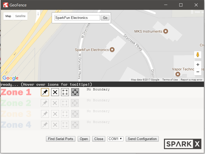
Let's make some zones around the SparkFun headquarters. I'm going to type "SparkFun Electronics" into the search bar and click "Go". After zooming in a little (either using your mouse scroll wheel or the zoom controls in the bottom right corner of the map) you should be looking at SparkFun HQ.

Now it's time to define Zone 1. First we'll put the zone into edit mode by clicking the push-pin button next to the Zone 1 label. You should notice that the other zones are grayed out to show that you're editing Zone 1.
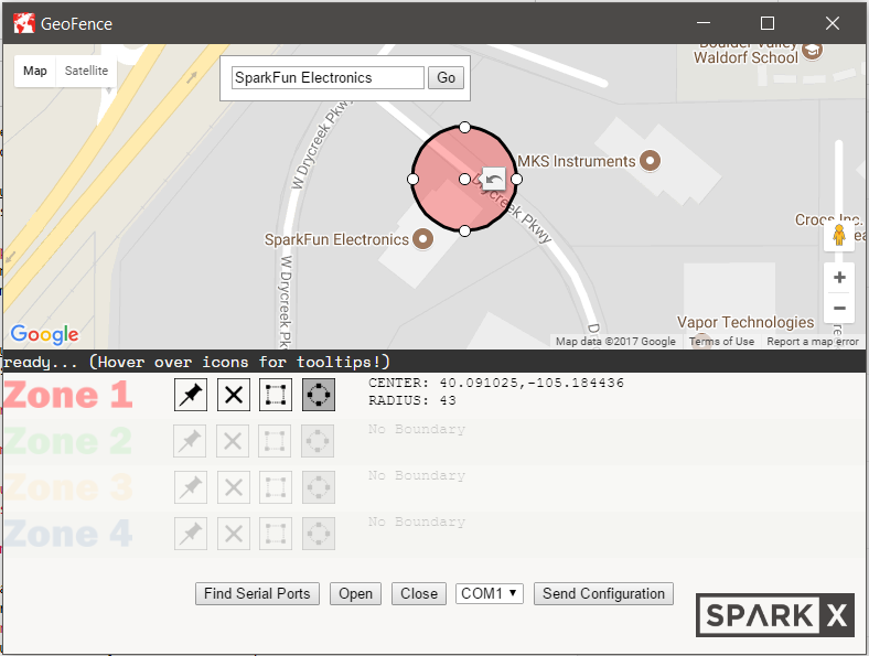
Now try clicking somewhere on the map... You should have just created a circular zone! Notice that the circle is the same color as the zone label, this is how you'll be able to tell the zones apart. Next, try grabbing the anchors along the outside of the circle and drag them to make the circle larger or smaller. If you want to change the circle's location while maintaining its size, you can drag it by the center anchor. If you'd like to erase this circle and place a new one, just click anywhere on the map and a new circle will be placed where you click. Notice as you move the circle that the coordinates in the zone coordinate table change.
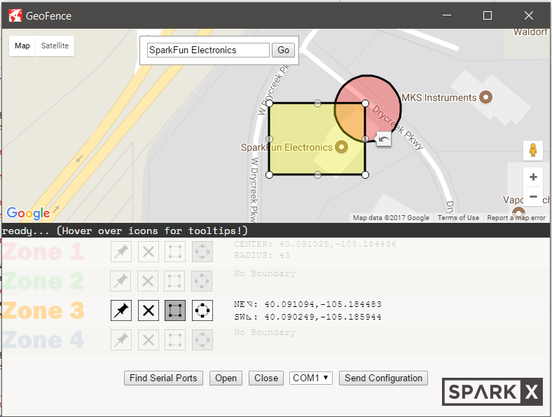
Now that we're done editing Zone 1, click the zone edit button again to exit edit mode. The anchors on your Zone 1 circle will disappear and the other zones will pop back into view. Let's select another zone and draw a rectangle this time. Click on the zone edit button beside Zone 3. Now since we want to make this zone rectangular, click on the rectangle button. Now click anywhere on the map to make a rectangular zone boundary. You can edit this rectangle the same way you edited the circle before. If you drag one corner of the rectangle into the circular boundary from before, you'll notice that zones can overlap. Because the GeoFence checks each zone separately, it's totally fine to have overlapping and nested zones!
Now press the edit zone button again to exit edit mode. Let's send these zone boundaries to the board! Connect a GeoFence board to your computer using a USB micro-B cable. If this is the first time you're connecting this board, you may need to give it a few seconds to configure. Now press the "Find Serial Ports" button to populate the drop-down list with all of the active serial ports.
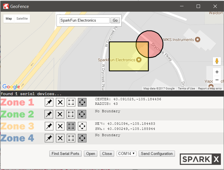
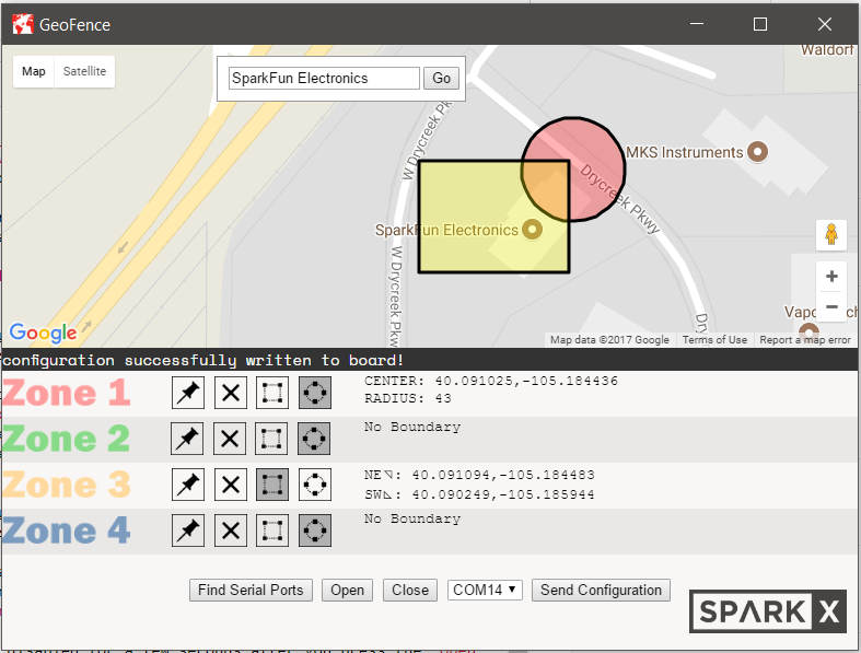
The status bar will tell you how many serial devices were found. Now select your board from the drop-down list. As you can see, mine is the only device connected, so I know it's on COM14. Press "Open" to open the serial port. This will cause the device to reset, so you'll need to give it a moment before pressing "Send Configuration". As a precaution, the "Send Configuration" button is disabled for a few seconds after you press the "Open" button. Now you can press "Send Configuration" and, if the configuration was successful, the status bar should say so after a few seconds. You may also notice the zone LEDs on your hardware flashing in order. Congratulations! You've just set up a geofence!
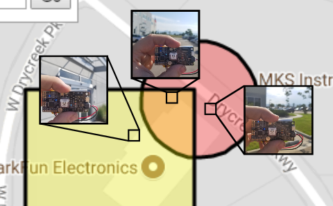
Now set up some zones in your own neighborhood and take your GeoFence board for a walk. Connect a lithium ion battery and walk around looking for the edge of your zone boundaries. Zones are accurate down to about 3 meters so they can be pretty small if you need them to be and very precisely placed. Here are some shots of my board with the configuration we just created:
Here are a few common problems that you might run into when using the GeoFence.
If you have a lot of serial devices connected to your computer, it may be difficult to tell which one is the GeoFence hardware. The easiest way to figure it out is simply to unplug the GeoFence and press "Find Serial Ports" in the GeoFence App. Take note of which ports are listed. Now connect your hardware and click "Find Serial Ports" again. There should be a new port in the list now which corresponds to your board.
This will happen if the board is having trouble parsing the configuration that you're sending from the software. The board and software will try 4 more times to send the configuration before aborting. If it fails all five attempts, try the troubleshooting tips below:
First of all, ensure that you've clicked the "Open" button to open a serial connection to your board. Press "Close" and then "Open" again, give the board a moment to reset, then try sending your configuration again. If it still doesn't work, you may need to reset the board. Close the serial port and press the reset button on your GeoFence board. Now open the serial port again, give it a moment to reset and send your configuration again. It may need to do this a few times before it will work. When it's successful, the status bar will give you a success message and the zone LEDs on the board will flash in sequence.
Unfortunately there is not yet any feature that will allow you to save a configuration file and retrieve it later. However, if you would like to configure a stack of identical boards, you can simply configure them one after another by sending your configuration, closing the serial port, connecting the next board, selecting the proper serial port, opening that serial port, configuring that board and repeating the process until all of the boards are configured.
Make sure that your GPS module has a clear view of the sky. GPS doesn't work very well inside buildings, under bridges or beside large structures. If your board is inside an enclosure, you may need to attach an external antenna to get a good lock.
If you're interested in digging deeper into GPS, check out some of our GPS related tutorials!
learn.sparkfun.com | CC BY-SA 3.0 | SparkFun Electronics | Niwot, Colorado