If you have been wanting to design your own 3D printed object, Tinkercad is a great starting point. Advanced modelers may prefer programs like Fusion 360, SolidWorks, and Blender, but these can have a steep learning curve. If you are looking to design your own 3D printed object in a modeling software, Tinkercad can get you there in no time.
This tutorial will walk you through designing a simple project box. It has been designed to hold an Arduino Pro Mini. While this may seem fairly useless, you are encouraged to change the dimensions to meet the needs of your own project.
You will not need any components to follow along with the modeling part of this tutorial. Should you wish to print and build the box, you will need access to a 3D printer. This tutorial shows you how to use the Cura (LulzBot Edition) slicer program and print on a LulzBot.
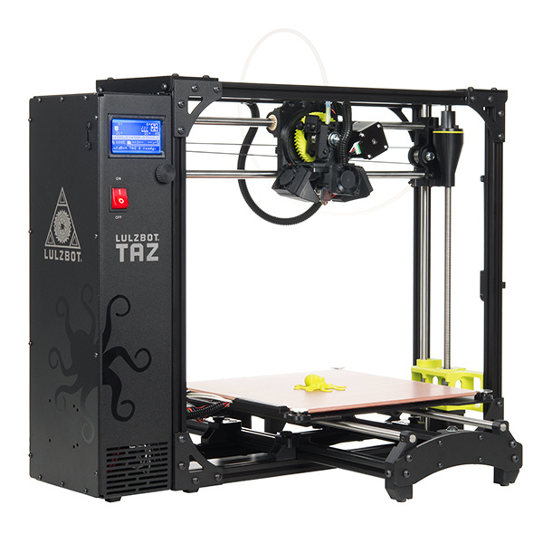
Depending on your 3D printer, you will want to be familiar with its basic operation. This guide shows you how to operate the LulzBot TAZ 5, but many printers have a similar operation. These documents might be helpful:
The advantage of 3D printing your project enclosure is that you get to make it the exact size of your project! You're also able to add any features, such as mounting holes and side ports to access USB, power, etc.
To start, lay your parts (electronics, motors, switches, etc.) on a flat surface, and orient them in a way that you think is the most space efficient. For this tutorial, we'll create a box that fits the Arduino Pro Mini, but you can modify the dimensions to fit your own project. Use a ruler or set of calipers to measure the outer dimensions of your project (also known as the "footprint"). This is the minimum amount of area we'll need in the base of the box.
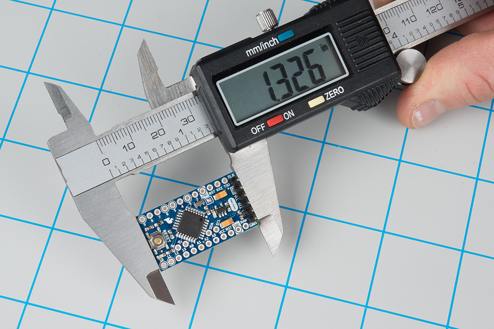
Let's start by measuring the length (remember, this can be anything: a collection of PCBs, candy, your perpetual motion machine, etc.).
Then, let's measure the width of the board.
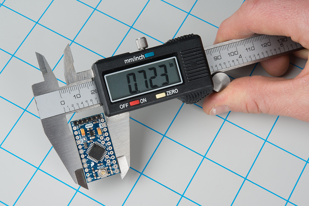
The electronics portion of the project (just the Pro Mini in this example) has a footprint of 1.326 x 0.723 inches. This guide shows things in inches, as most of the SparkFun boards were created with the Imperial system. Feel free to change to Metric. Next, we want to measure the maximum height of the pieces to be enclosed.

As you can see, the maximum height of the Pro Mini (with headers) is 0.457 inches.
We'll want to round up our measurements to allow for some wiggle room in the enclosure. For this example project, we'll use the following dimensions for the required cavity size:
To attach a lid to our enclosure, we'll want to add some screw holes to the box as well as create a lid with similarly placed holes. We'll print both of these items at the same time.
There are several ways to attach screws to a 3D printed object. One of the most robust methods is to use heat-set inserts. You can use use a soldering iron to push these into an opening, which melts the plastic. Once it cools, the insert will be firmly embedded in the plastic, and you can use them as screw taps.
For our quick-and-easy enclosure, we'll just make holes slightly smaller than the screw size so that the thread bites into the plastic. It won't hold as well as a heat-set insert, but it should be good enough for prototyping purposes. Ideally, you will want self-tapping screws intended for plastic, but machine screws will work in a pinch.
For more information on how to join 3D printed parts using screws/bolts, including heat-set inserts, see this article.
We'll be using #4-40 screws to affix the lid to the enclosure. As a result, we'll want to look up the sizes of the holes we'll need. Take a look at this tap and drill size chart from Michigan Tech. You can see that for a #4-40 screw, we'll need to drill a hole with a diameter of 0.0890 inches (tap drill size) for the screw's threads to bite into the material. These holes will be put into the base of the enclosure. For the lid, we'll want the screws to be able to freely spin, so we'll use the free fit drill size, which is 0.1285 inches.
Most fused filament fabrication (FFF) 3D printers, like our LulzBot, do not have great tolerances or resolution (e.g. down to the 0.001 inch). The molten plastic that comes out of the extruder also has a habit of "melting" a bit around the edges, which can cause holes to shrink. In addition, using self-tapping screws forces some of the material to move out of the way, which can cause stress and fractures in the plastic. As a result, we'll need to oversize the drill holes by 0.01 to 0.02 inches.
Read the tap drill size and the free fit size from the chart, round up, and oversize it by about 0.01 inch:
From here, it can help to sketch out what we want the enclosure and lid to look like. Adding dimensions will help us when we go to model it in the next section. Just to give us even more room, let's round up the required cavity space to the nearest 0.5 inches. Because the posts in the corners (that hold the screws) are each 0.25 x 0.25 inches, this will make our entire enclosure's footprint come out nicely to 2.0 x 1.5 inches.
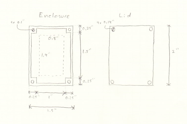
We'll use these dimensions in the next section to model the box in Tinkercad.
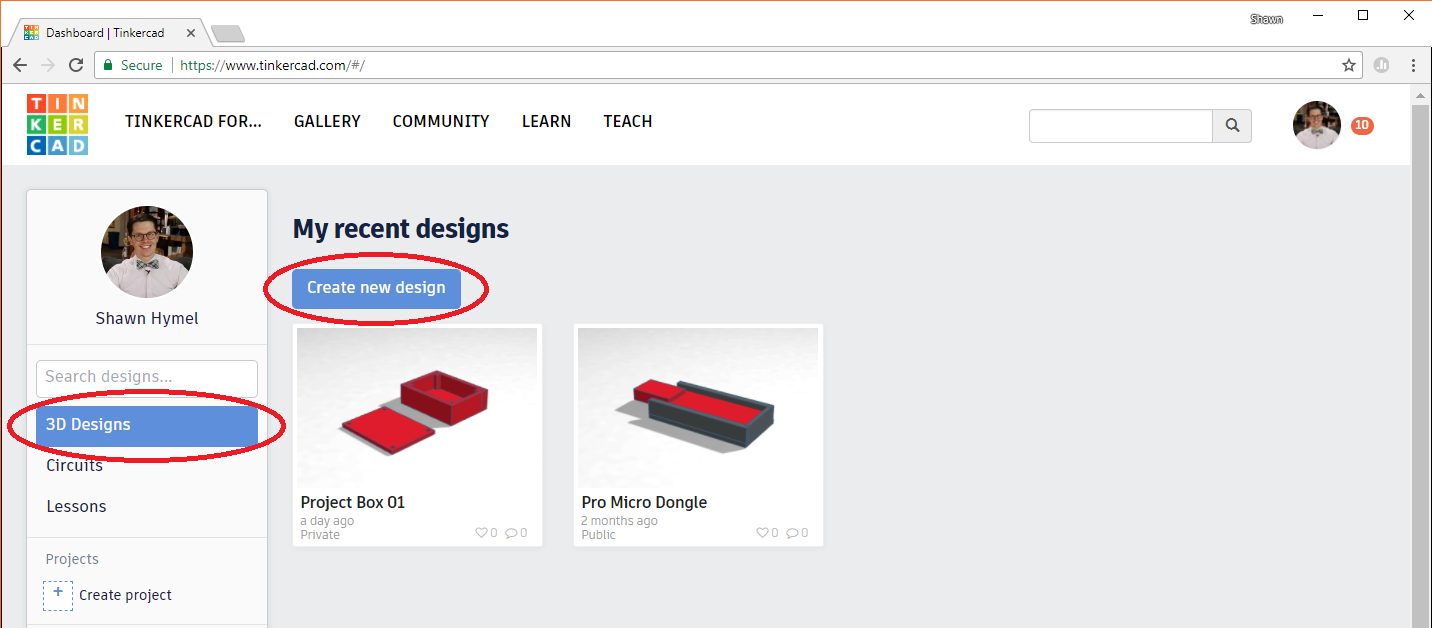
Navigate to tinkercad.com, and sign up for a new account (if you don't have one already).
Once you've logged in, make sure 3D Designs is selected on the left and click Create new design.
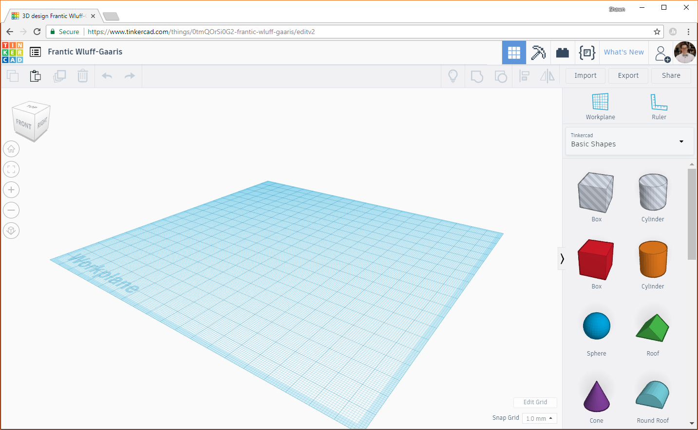
You'll be presented with a blank workplane and a number of shapes on the right side. The basics of Tinkercad are simple: you drag a shape onto the workplane, modify it, and combine it with other shapes. If you right-click and drag on the workplane, it will rotate. If you middle-click and drag on the workplane, it will pan. Try playing around with rotating and panning your workplane to get a feel for how it works.
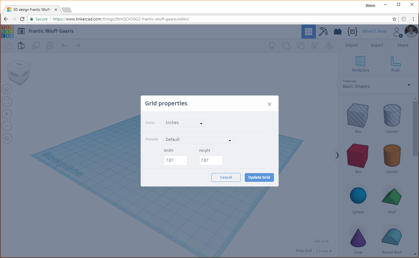
We'll want to work in inches for this project, so click Edit Grid in the bottom right of the Tinkercad window. You should get a pop-up with some options. Change Units to Inches.
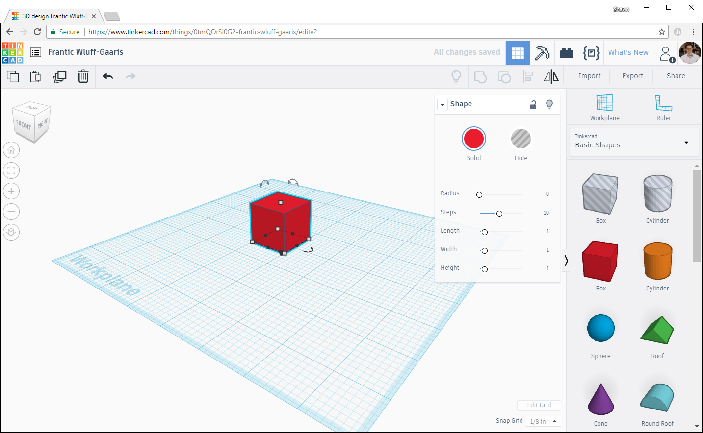
Click Update Grid. At the top left, you should see the name of your project, which should have been given some random sequence of words (for example, mine was named "Fantic Wluff-Gaaris"). You can click on the name and change it to anything you'd like. I'll keep mine as Fantic Wluff-Gaaris because it's awesome (albeit not terribly descriptive).
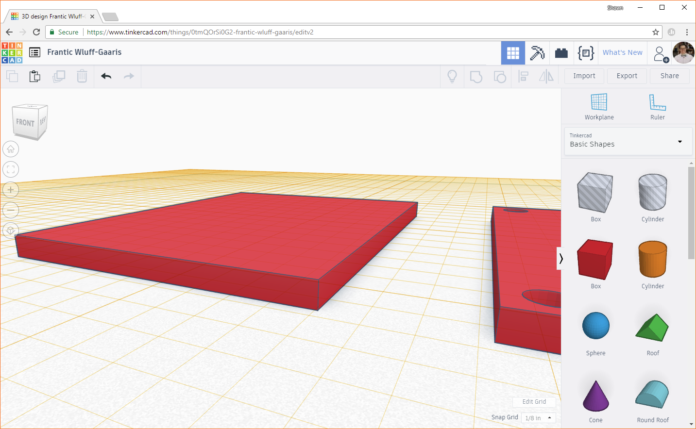
Click on the red box (from the list of shapes on the right side), and drag it to somewhere near the middle of the workplane. Note that everything we do is relative to the workplane, and we can move the workplane to make things easier (which we'll do in a future step).
Zoom in on the box using the buttons on the left side (or your mouse wheel). Rotate and pan the workplane as necessary to get a good view of your box. With the box selected, click on the red color swatch above the word Solid on the object properties window. From there, you can select the color of your box. No, it won't affect the color of the print (that comes from the color of the filament that we'll choose), but it might make your 3D model easier to see in Tinkercad. I'll leave mine as red; it's a good color.

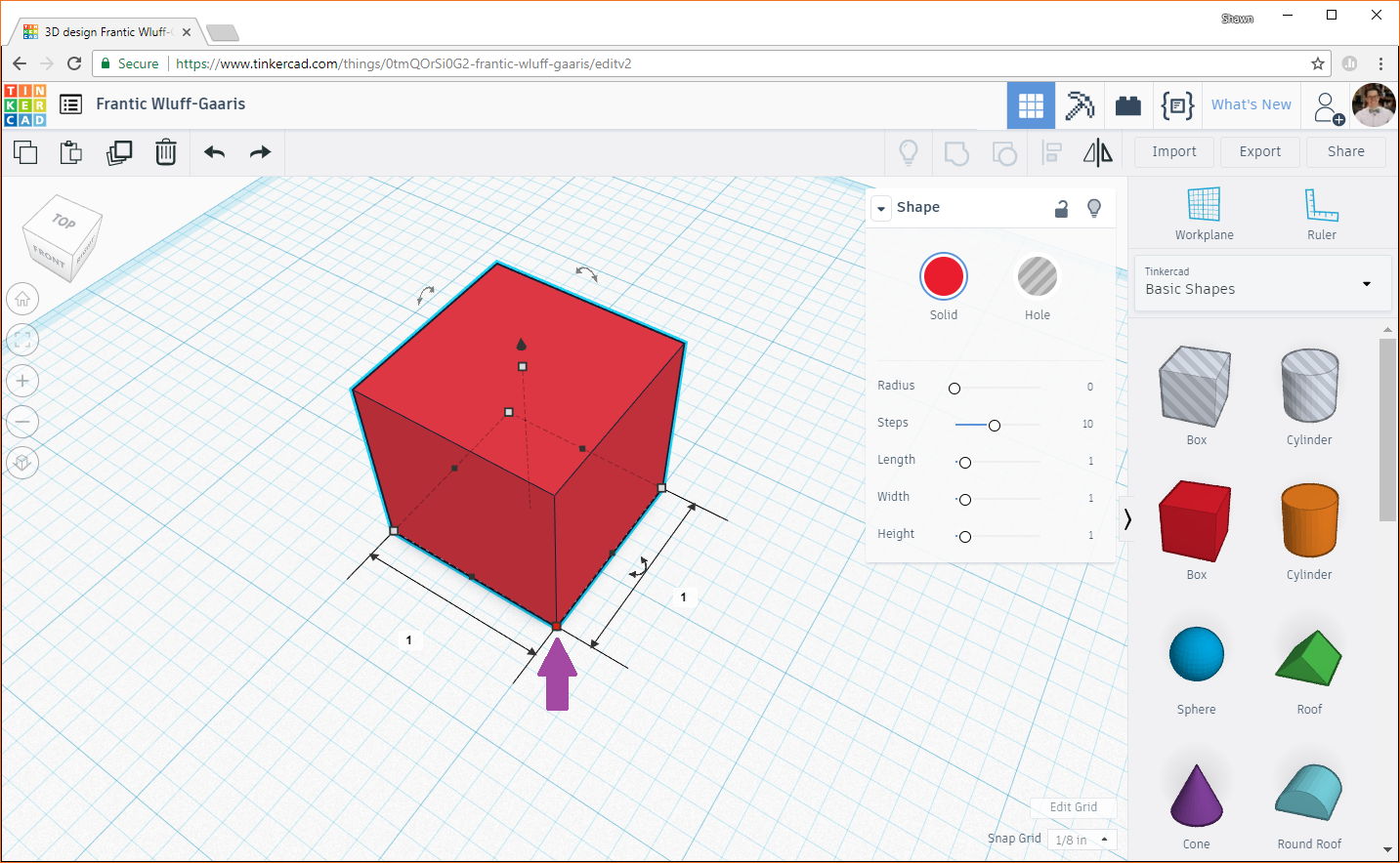
Click on one of the corners (gray squares), and you should see the footprint dimensions of the box appear on the workplane (you can see that the footprint of the box is 1 x 1 inches).
Click on one of the dimensions to edit it.
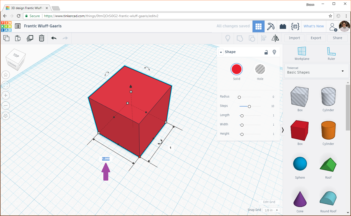
We'll make this dimension the width of the enclosure, so type 1.5 and press enter. Click on the other dimension (the length, in our case), and enter 2.0. Your cube should turn into a rectangular box.
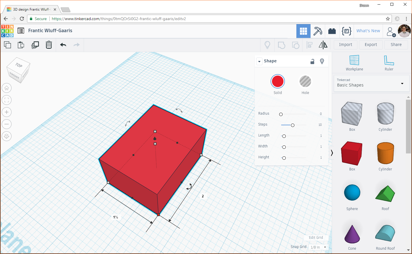
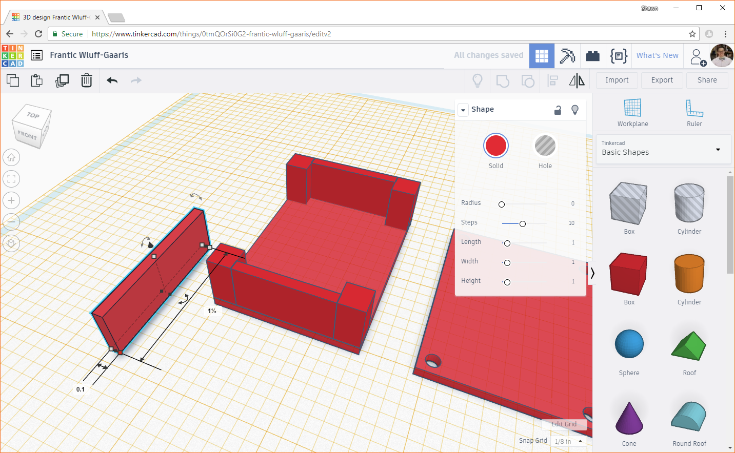
Click on the height node (gray box in the middle of the top of your box object). This will display the height (in inches) of your box.

Click on the dimension (1 in this case) and change it to 0.1. In my experience, 0.1 inches is a good thickness for walls for an enclosure like this. Any thinner, and they become quite flimsy.

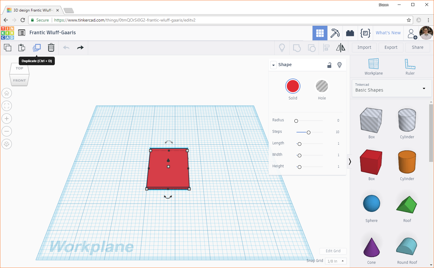
This box will act as the base of our enclosure. We will build the screw posts and walls up around it. However, the lid for our enclosure looks exactly like this base (but with screw holes). To make life easier, let's just copy this base. Click on the box, and then click the Duplicate button on the top left.
You should now have two of the same boxes taking up the same space. Click on one and drag it over a few inches, making sure to leave a gap between them.
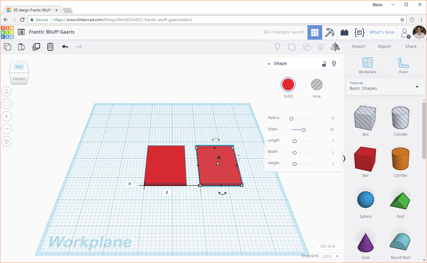
At this point, we should have the foundation for the base of the enclosure as well as the lid.
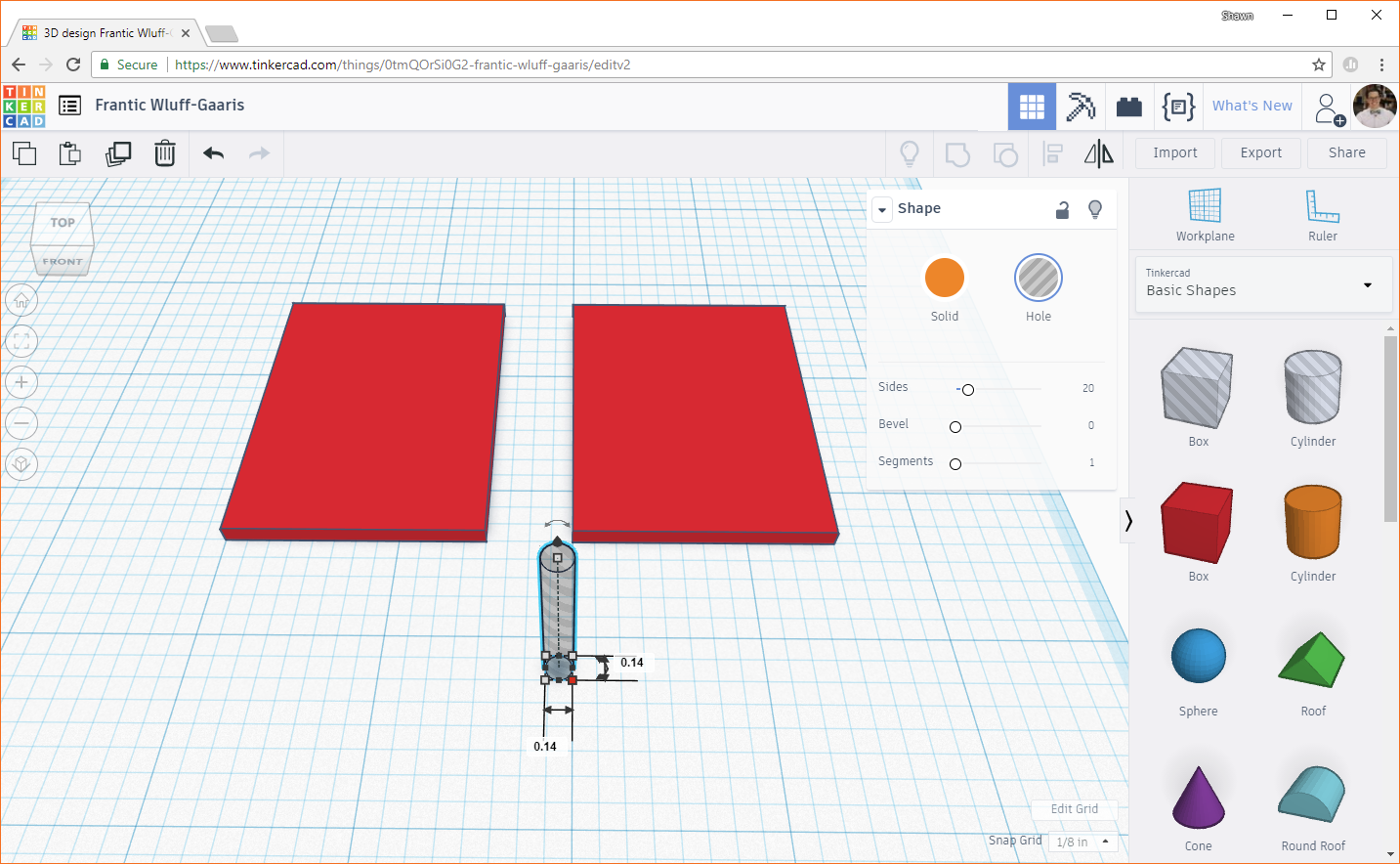
Let's make screw holes in the lid next. Above the red box and orange cylinder objects on the right pane, you should see a box and cylinder with gray stripes. These are "hole" objects that are useful for cutting, notching, and drilling into other objects. It's helpful to think of them as negative objects that subtract parts from other objects.
Drag one of the gray striped cylinders to the workplane and change the width and height dimensions to 0.14 inches (remember from the drawing: the screw holes in the lid need to have a diameter of 0.14 inches). The height doesn't matter, as we'll be using these to "drill" into the lid (so long as it's at least as tall as the lid).
Because everything is relative in Tinkercad (there is no 0,0 origin, unless you create an arbitrary one with the ruler--but we won't need to do that for this tutorial), we will need to align the cylinder with the corner of our lid and move it from there to precisely place it. Select both the cylinder and the second box we created (left-click and drag a selection around them, or hold shift and click on both the cylinder and box).
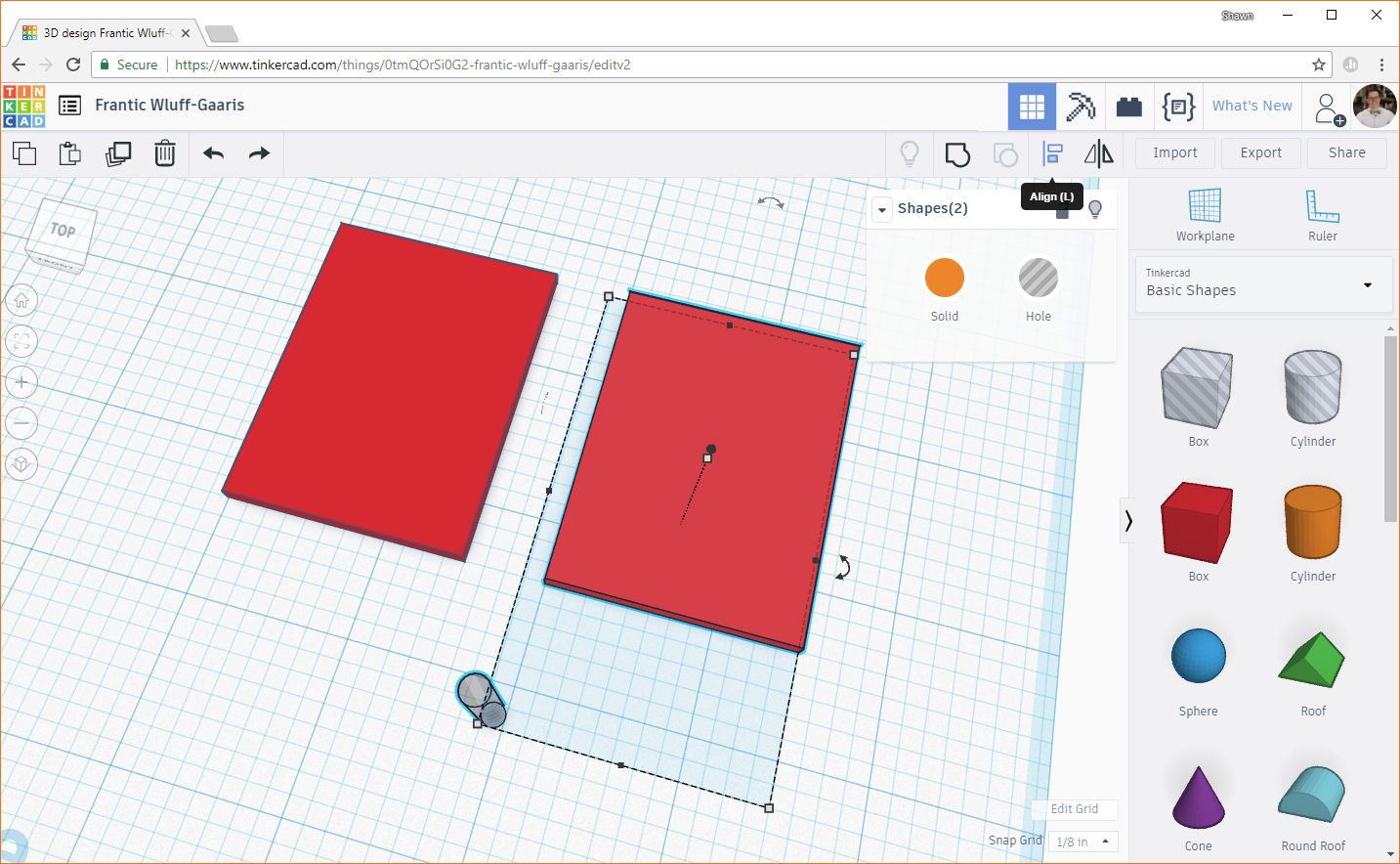
In the upper-right corner, select the Align button. You should see several black dots appear around both of your selected objects. If you hover your mouse over one of these dots, you should see an outline of where the objects will move to should you click it. But don't click!
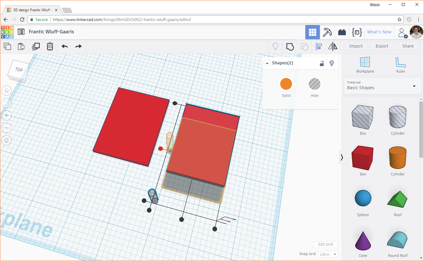
We don't want both objects to move! We just want the cylinder to move in relation to the box. To accomplish this, click on the box (the one that we have selected). You should see the set of black dots disappear and another set appear around the box. This indicates that the box will stay still and the cylinder will align with the box (instead of both objects moving). Hover your mouse over the bottom black dot on the left side. You should see an outline of where the cylinder will move.
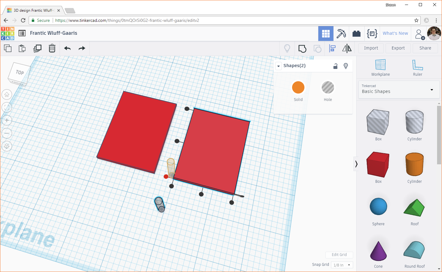
Click the black dot (bottom dot on the left side) to move the cylinder. This aligns the bottom of the cylinder with the bottom of the box.

Click the left-most dot on the bottom side of the box to align the left side of the cylinder with the left side of the box.
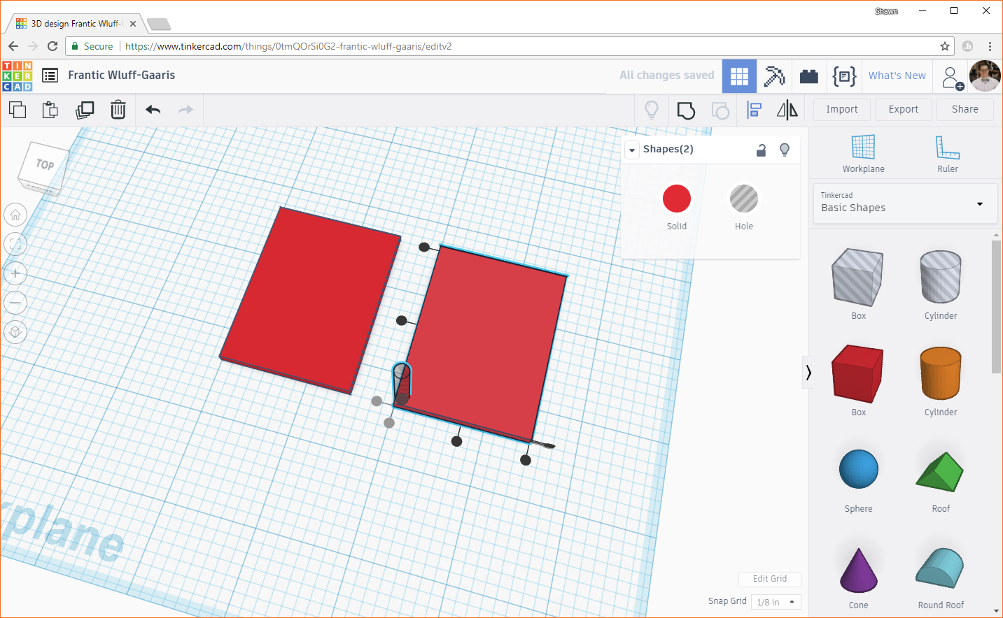
If we were to subtract the cylinder from the box to get our hole right now, we'd end up with some edges of the walls with 0 thickness, which doesn't make for a very strong mounting hole. To fix this, we need to move the cylinder in toward the center of the box by a small amount.
We want the screw holes to line up in the center of the posts, which have a footprint of 0.25 x 0.25 inches. This means that the center of each post is 0.125 in from each side of the corner. Right now, the center of the cylinder is 0.07 inches away from each side of the corner. This means that we need to move the post 0.055 inches in from each side in order to line up with the center of the post (0.125 - 0.07 = 0.055). Here is a diagram of how we came to that measurement:

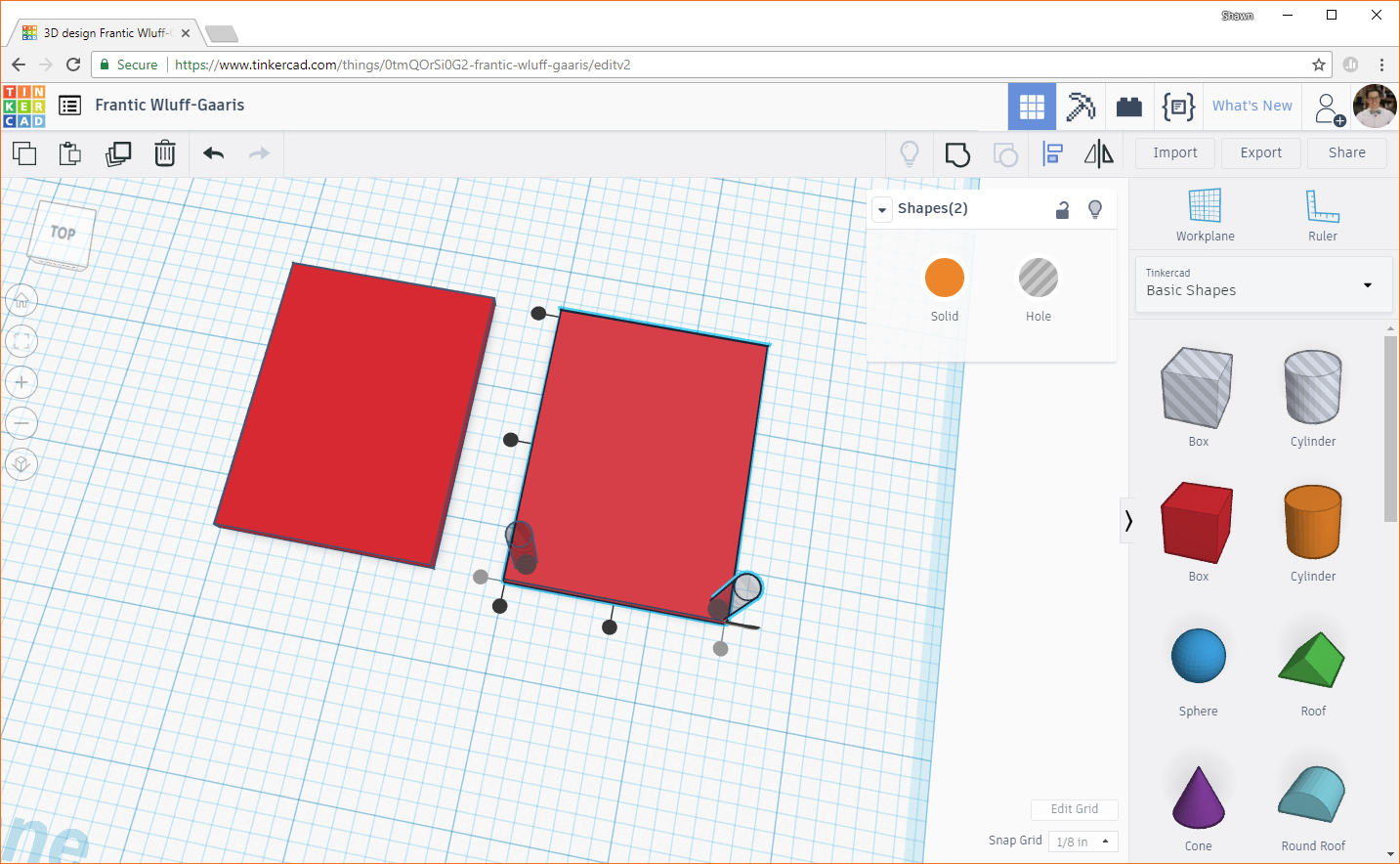
Click on the cylinder and begin to drag it toward the center of the box. You should see a couple of numbers appear showing how much you're moving the object in the X and Y directions (along the plane--note that we can't move objects in the Z direction by dragging them).

Click on one of those numbers to edit it. Pay attention to the sign! If you see a negative sign (for example, in the picture above), you need to keep your number negative. We need to precisely move the hole in 0.055 inches from the sides. From the picture above, change -1/4 to -0.055 and change 0.235 to 0.055.

Duplicate the cylinder, and align it to another corner.
Move the cylinder in toward the center, and edit the values so that it moves exactly 0.055 and 0.055 inches (remember to watch your signs!).

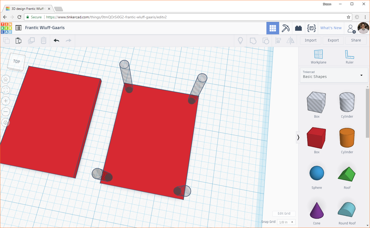
Repeat this process for the other two corners. You should have 4 "hole" cylinders in the corners, and each should be 0.055 inches away from their closest walls.
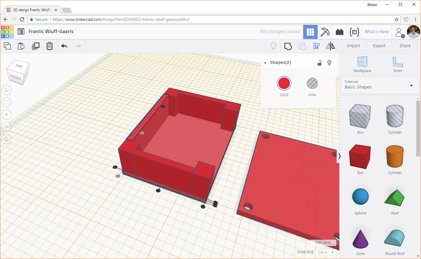
Click and drag a selection box around the lid and four cylinders (or hold shift and select each object). Make sure you do not select the other box!
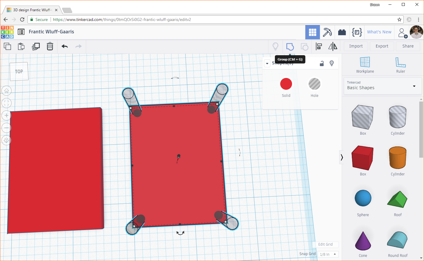
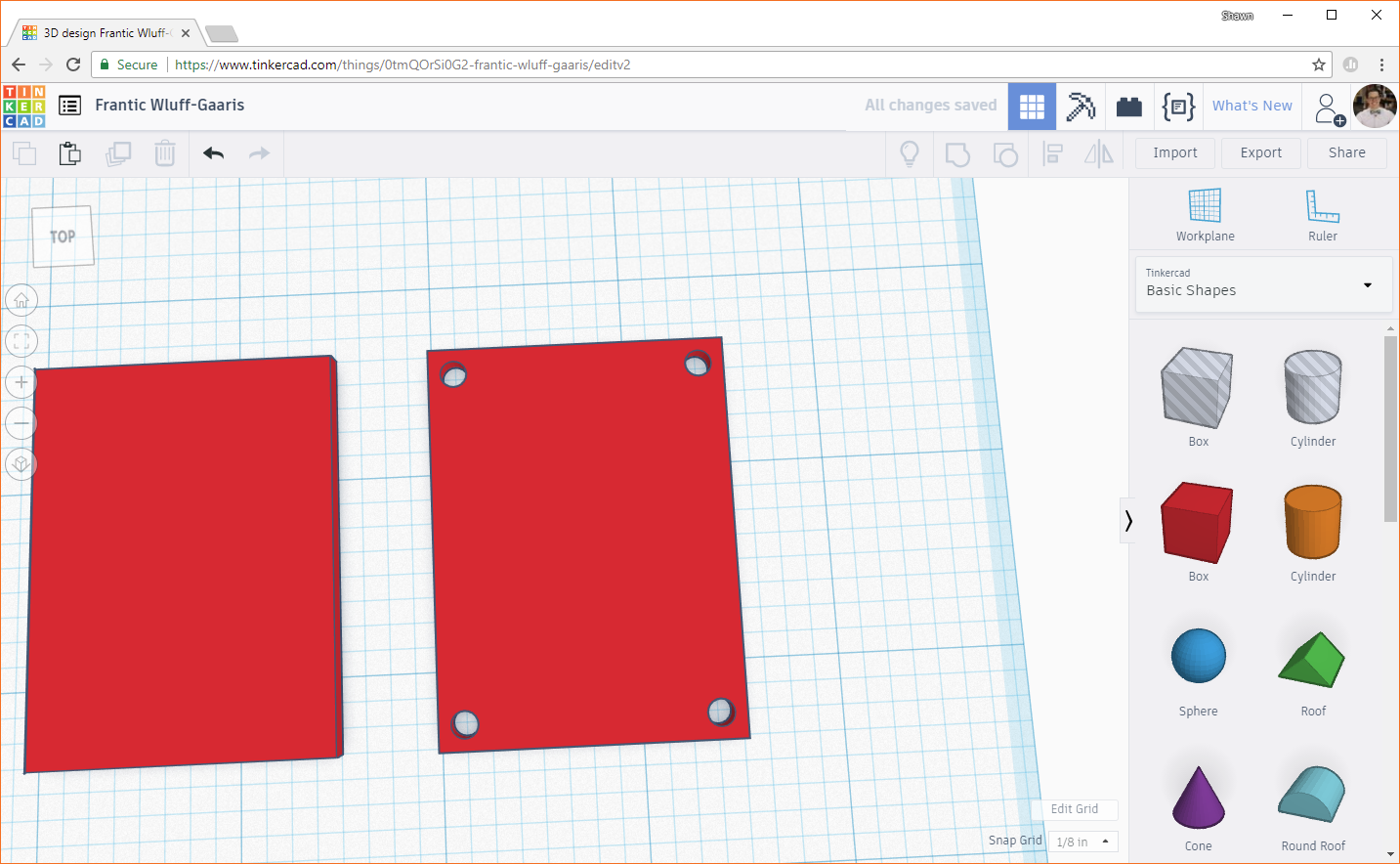
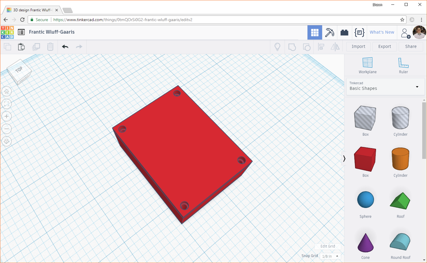
In the top right corner, click the Group button. This will combine any selected objects into one object. Solid shapes (like our boxes) will be added together. Negative shapes (like our "hole" cylinders) will be subtracted from solid shapes. This has the effect of "drilling" or "carving" out shapes. You should see our lid with 4 holes drilled in the corners.
We need to make the posts on the main enclosure body next, but first, we need to move the workplane. The workplane is the 2-dimensional area that provides an area for objects to be created on, and we can move it to be parallel with any surface of an object we've already created. By moving it up to be in line with the top of the enclosure's foundation, we can make the posts directly on the top of the foundation. That way, we don't have to move the posts up (in the Z direction) later.
Click on the Workplane button in the top right of the window. You should see a square with a cone sticking out of it appear on your cursor. Hover over the top of the foundation. The square shows the orientation of the plane (parallel to the top of the foundation), and the cone shows the direction of positive Z (positive Z will be up away from the top of the foundation).

Click, and you should see the workplane move to the top of the foundation and turn yellow (to show that it is a user-defined workplane as opposed to the blue default workplane).
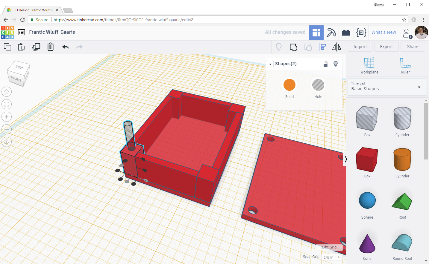
Add another solid box to the workplane. Change the footprint (X and Y) dimensions to 0.25 inches each.
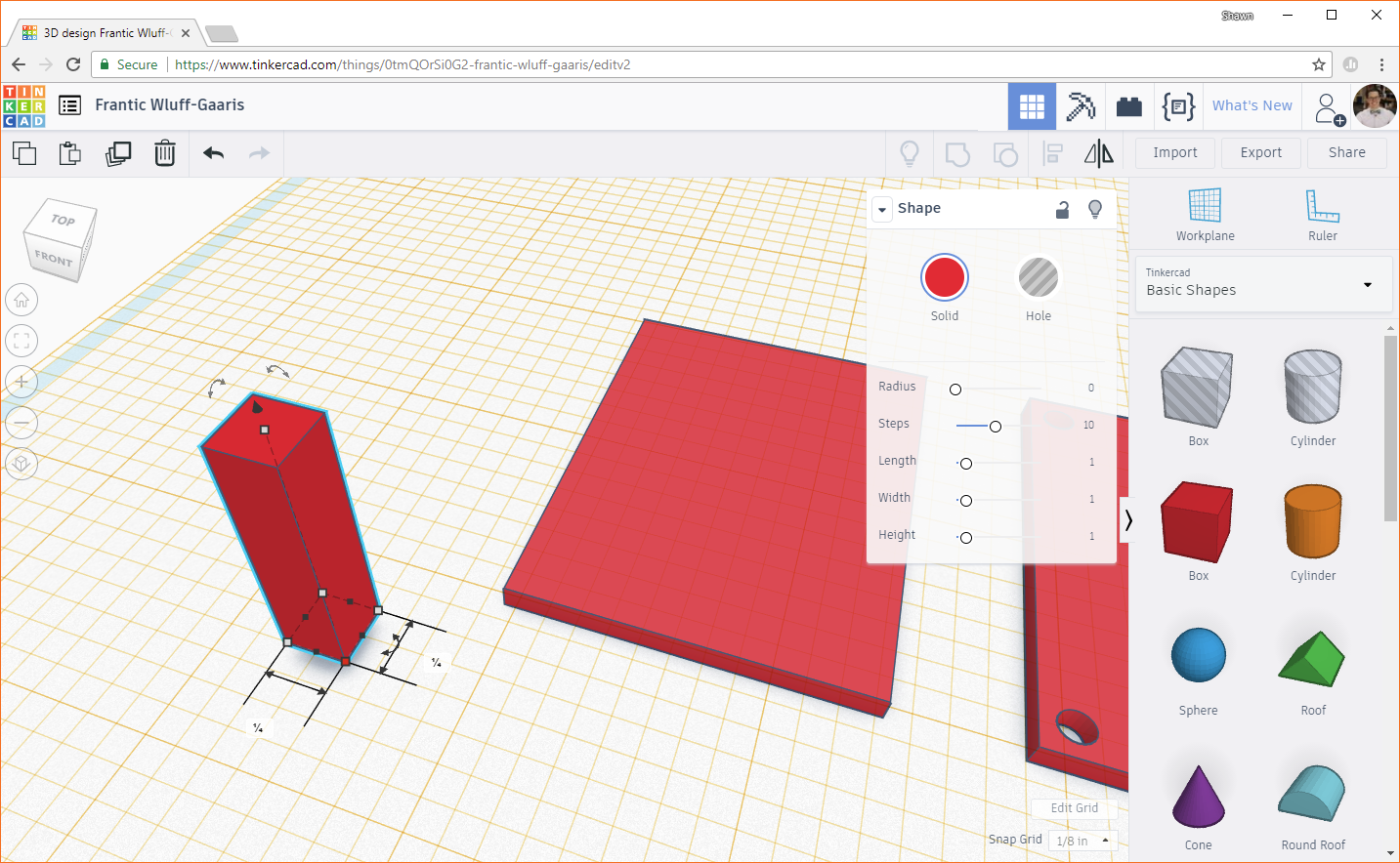
Change the height to 0.5 inches. The height of the posts determine the amount of space in the Z direction in the enclosure.
Use the Align tool to line up the corner of the post with a corner of the foundation.
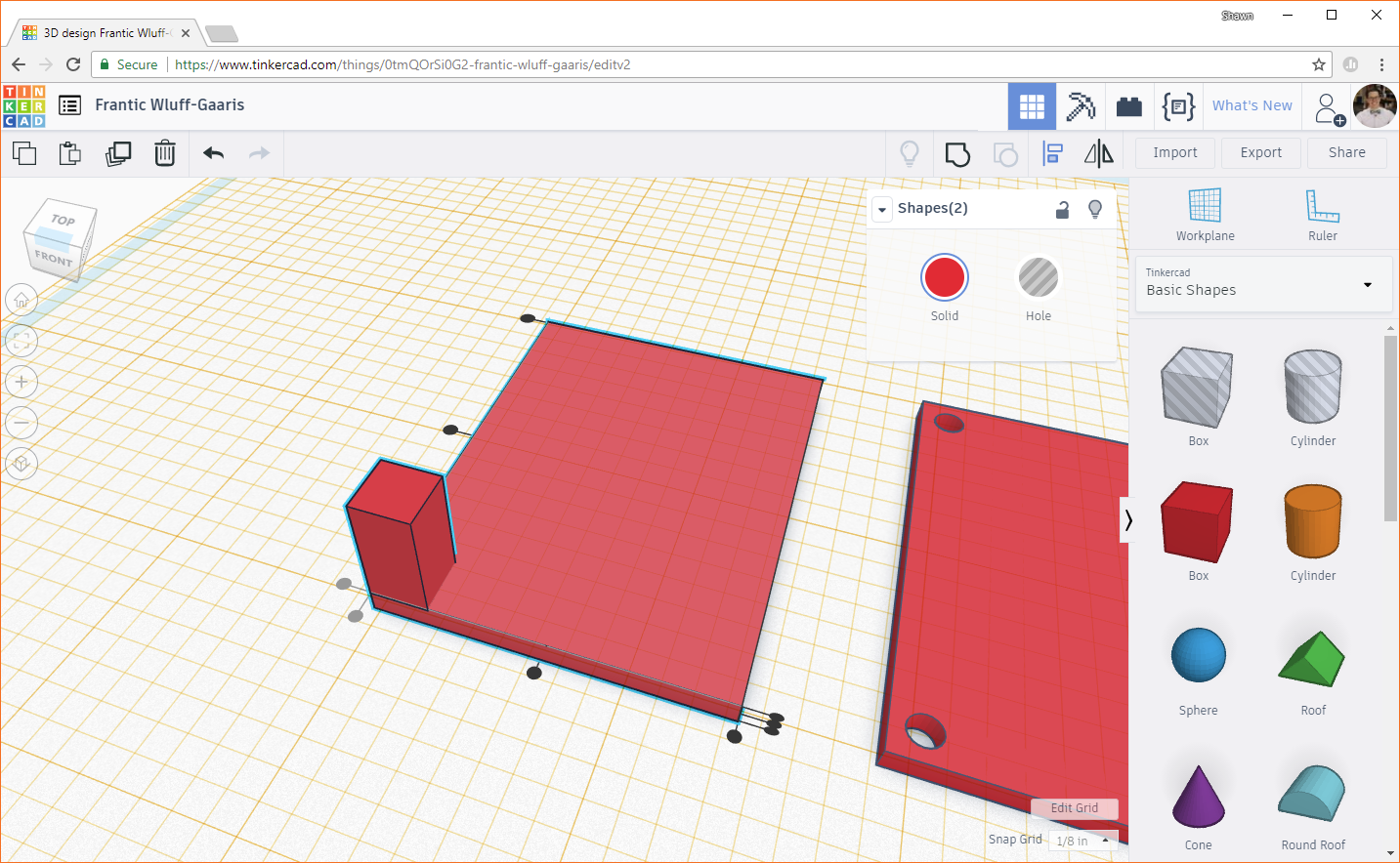
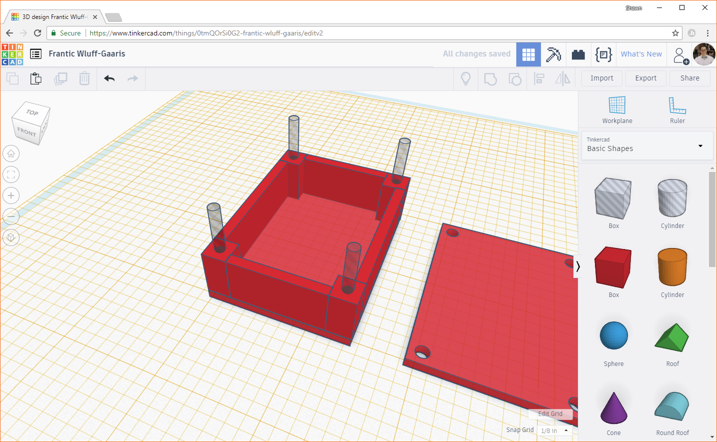
Duplicate the box 3 times and align each of them in a different corner of the foundation.
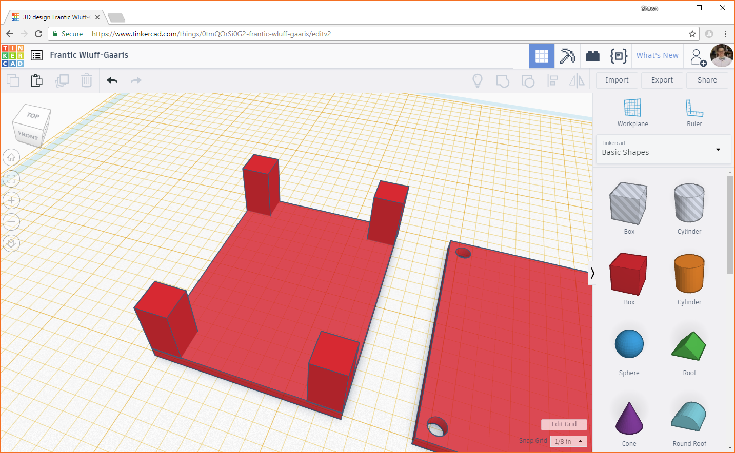
At this point, we'll want to add walls to the sides of the box, connecting our posts. Drag a box object to the workplane, and change the X and Y dimensions to 1.0 inches and 0.1 inches. Remember, the width of the box is 1.5 inches. Subtract the width of 2 posts (2 x 0.25 inches), and we get 1.5 - (2 x 0.25) = 1.0 inches. 0.1 inches is the thickness of the wall, which is the same as the box foundation and lid.
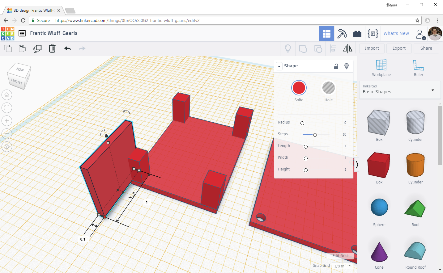
Change the height of the wall to 0.5 inches (which is the same height as the posts).

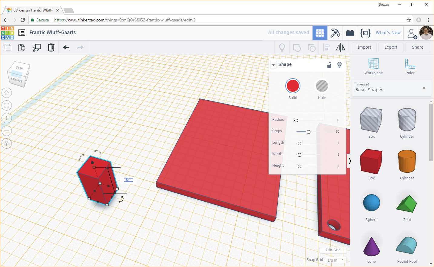
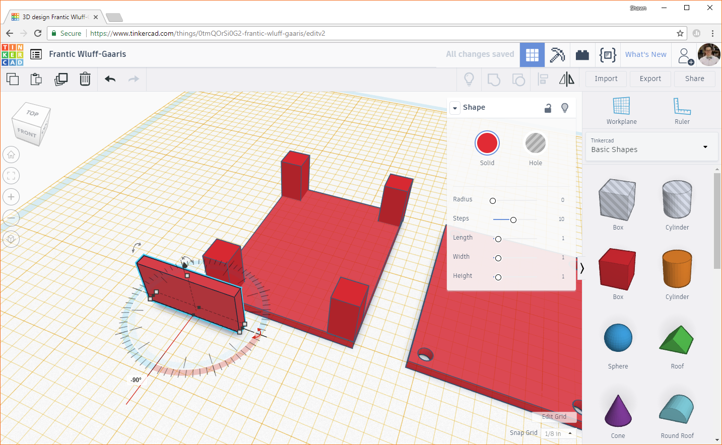
We want this wall to span between posts on the shorter side of the box. If you need to rotate the wall, drag and move the double-sided, curved arrow that's flush with the workplane. Rotate the wall 90 degrees or -90 degrees so that it is parallel with the short side of the box.
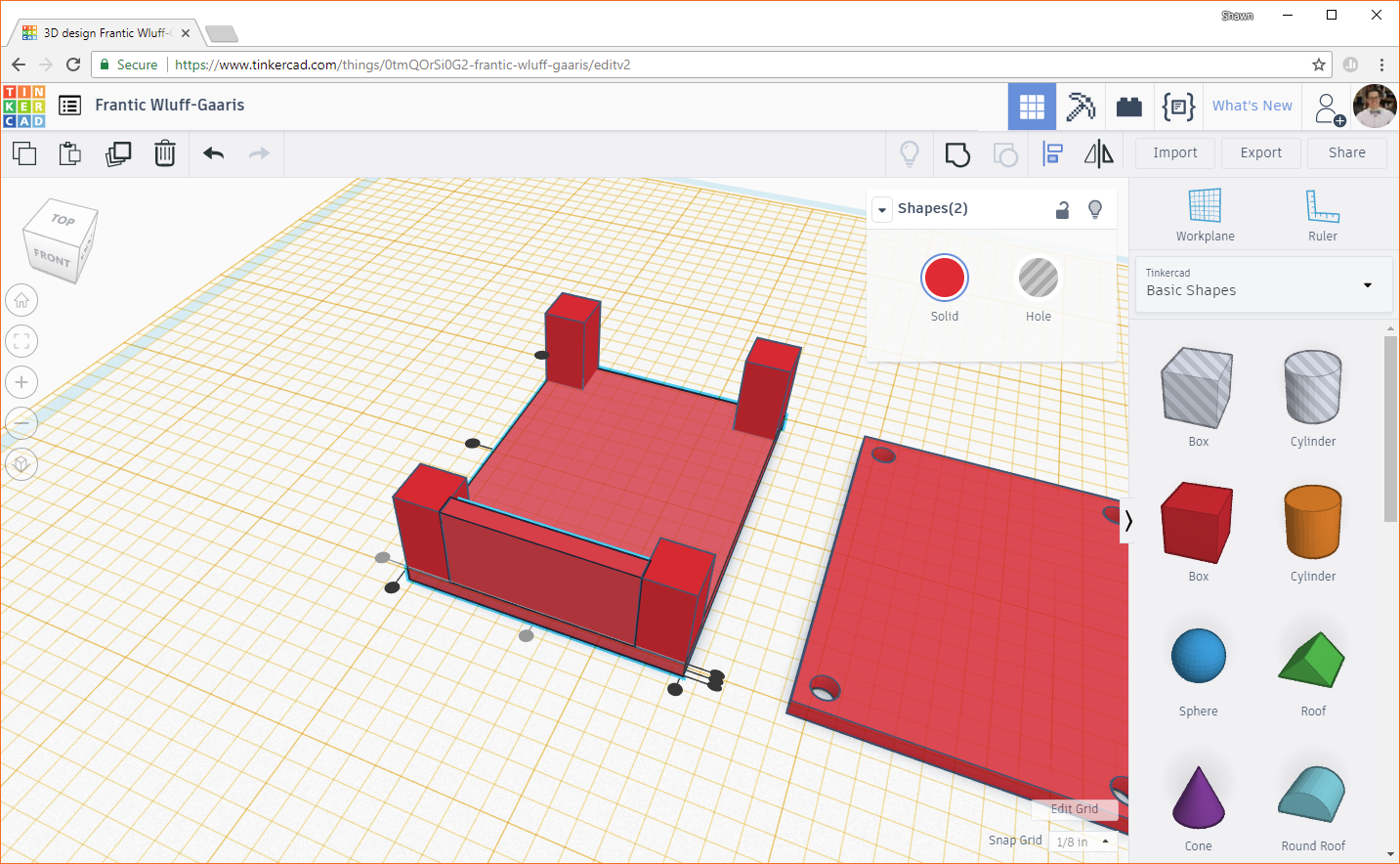
Highlight the wall and the foundation. Click the Align button. Click on the foundation to make the aligning dots appear around it. Click the dot in the middle of the short side to center the wall with the foundation.

Click the dot on the bottom of the left side to position the wall between the posts.
Duplicate the newly created wall and use the align tool to line it up on the opposite side.

Drag in a new box object, and change the X and Y dimensions to 0.1 inches and 1.5 inches. The length of the box is 2.0 inches, so 2.0 - (2 x 0.25) = 1.5 inches. Change the height to 0.5 inches.
Rotate the wall as necessary, and align it between two posts, constructing the wall along the length of the box.
Duplicate the wall, and move the copy to the other side of the box.

Drag a cylinder hole object to the workplane. Change the width and length both to 0.1 inches.

Use the Align tool to center the cylinder in the middle of one of the posts.
Copy the cylinder 3 times, and line them up in the middle of each post.
Select one post and its associated cylinder. Click the Group button to drill out the cylinder from the post.
Repeat this process for the other 3 posts and cylinders.

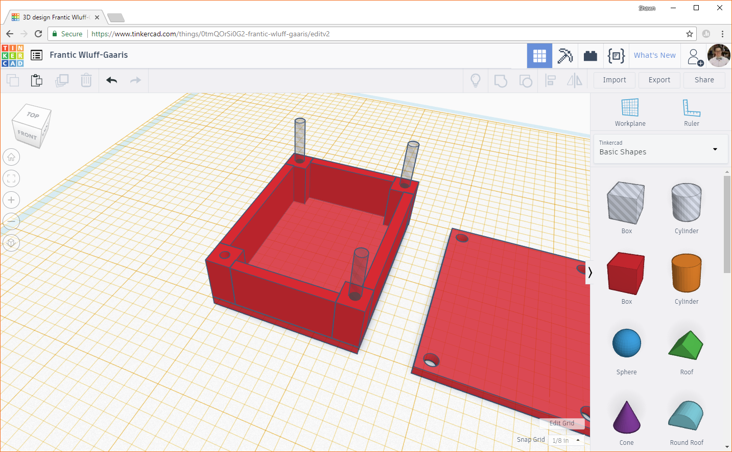
If you move the camera around, you should see that the holes are drilled into the posts but do not punch through the base. That's because we set the workplane at the top of the base, and any shapes we created stop at the workplane!
You could probably print these shapes as-is, but it's always helpful to do a little clean up and verify that everything lines up.
If you need to move the workplane back to its starting position, you can click on the Workplane button in the top right, and hover your mouse over the yellow workplane. You should see the plane cursor (square and cone) turn blue and white.
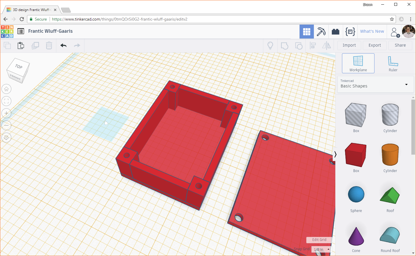
Click to reset the workplane back to its default position, where it should turn blue.
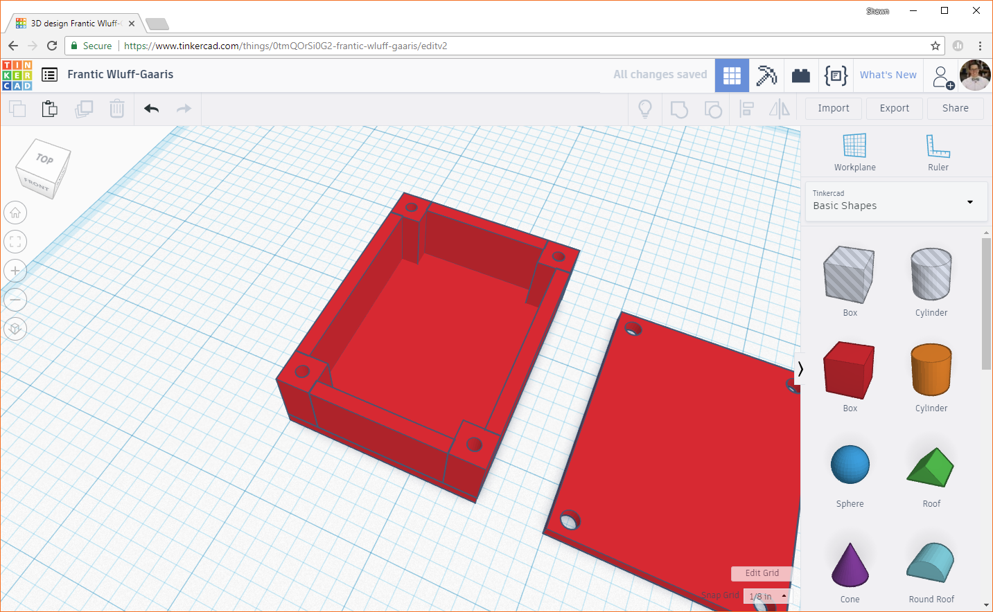
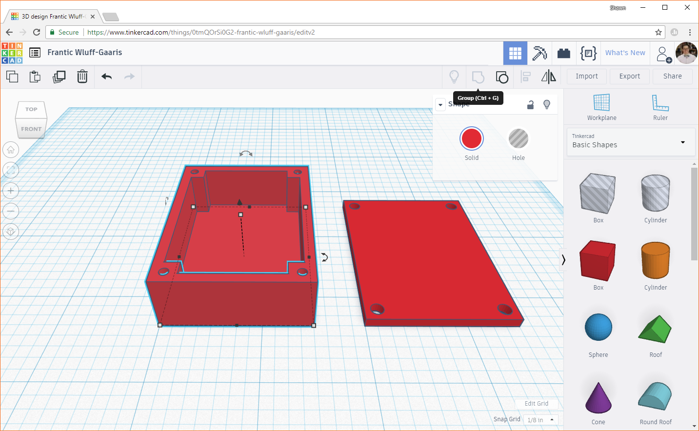
Right now, the box (minus the lid) is a collection of objects. Some printers may print it as one part, and some may not. It can help to group these objects to tell our slicer program that we want it to be one solid object. Select all the objects in the bottom part of the box (i.e. everything but the lid).
Click the Group button, and all the objects should combine into one.
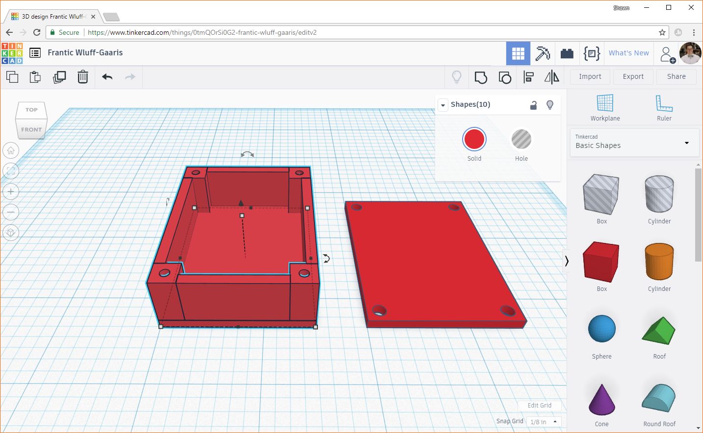
If you'd like to check that all the screw holes line up, you can move the lid to the top of the box, and look down the holes. Use the Align tool to move the lid precisely to the top. You might need to move the lid up slightly on the z-axis so that it's not inside the box.
Move the camera around to each of the holes to make sure everything is lined up. Once you've verified that the holes look good, press the Undo button (you can also use the keyboard shorcuts ctrl + z or command + z) a couple of times to reverse the changes.
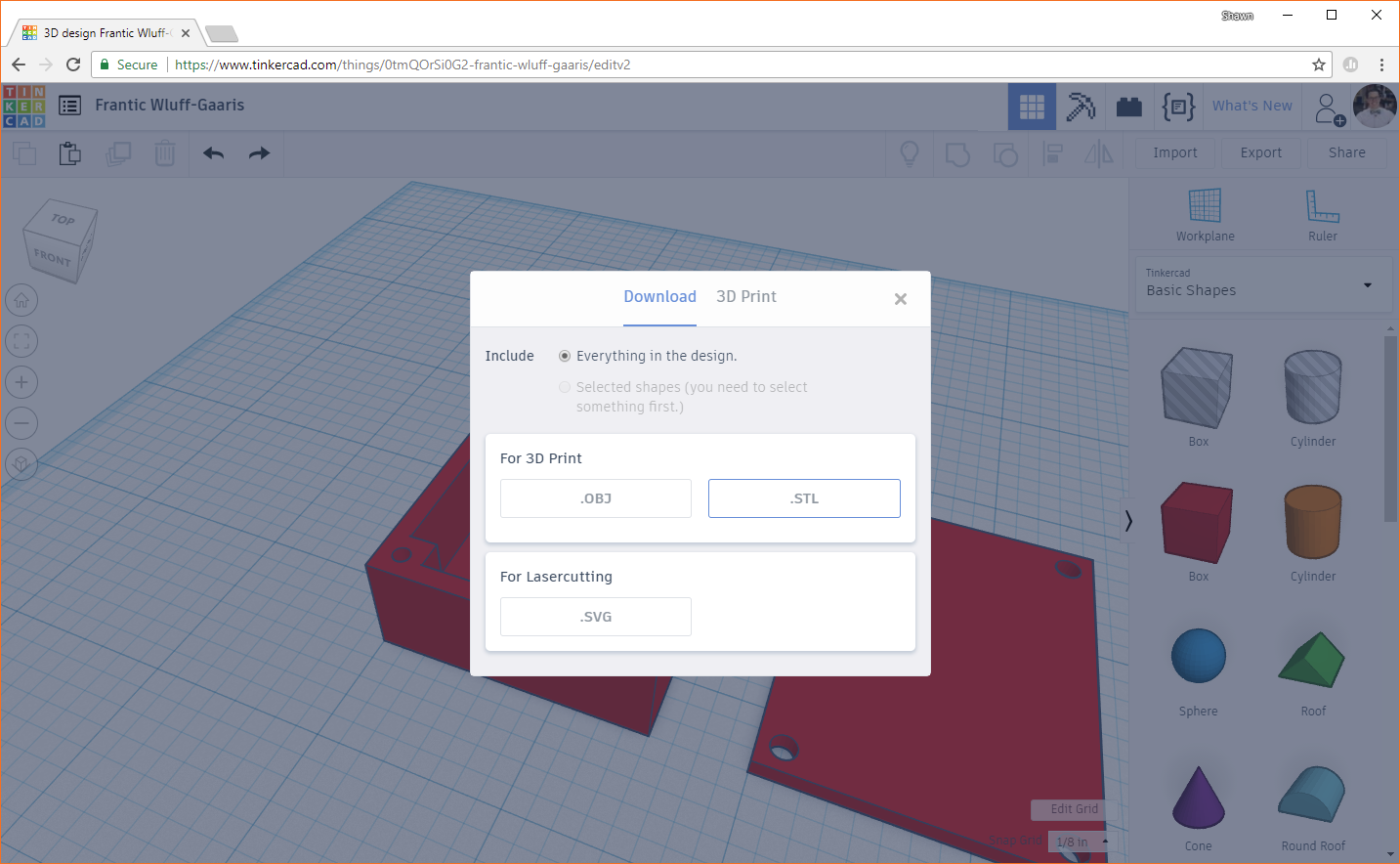
For many printers, we can't print directly from Tinkercad (especially for LulzBot). We need to export our design as a .stl or .obj file and then import it into a slicer program. In the top-right of Tinkercad, press the Export button. You should be greeted with a pop-up. The .obj file format is a more complex collection of files, and the .stl format is easier to work with. With our simple print, we'll go with .stl, so click on the .STL button to download your exported design.
A Slicer is a program that reads 3D models (for example, saved in an .stl or .obj file format) and translates them to the individual layers needed by the 3D printer. The program then generates machine code (often in g-code format) that can be read by the printer.
To start, download the Cura LulzBot Edition software:
Run the downloader, and follow any necessary steps to install it on your system.
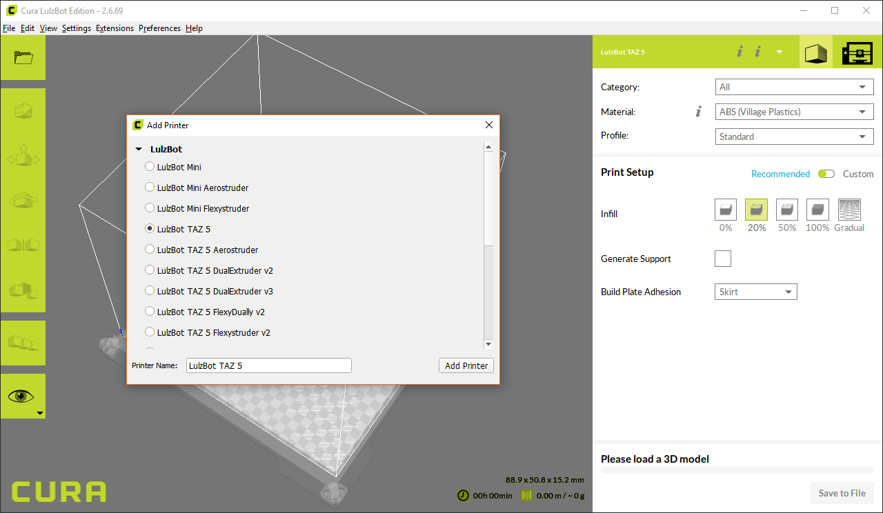
When the program first runs, it should ask you to select a 3D printer. If not, select Settings > Printer > Add Printer.... You should get a pop-up asking you to choose a printer. Select LulzBot TAZ 5 (or whichever LulzBot model you have), and click Add Printer.
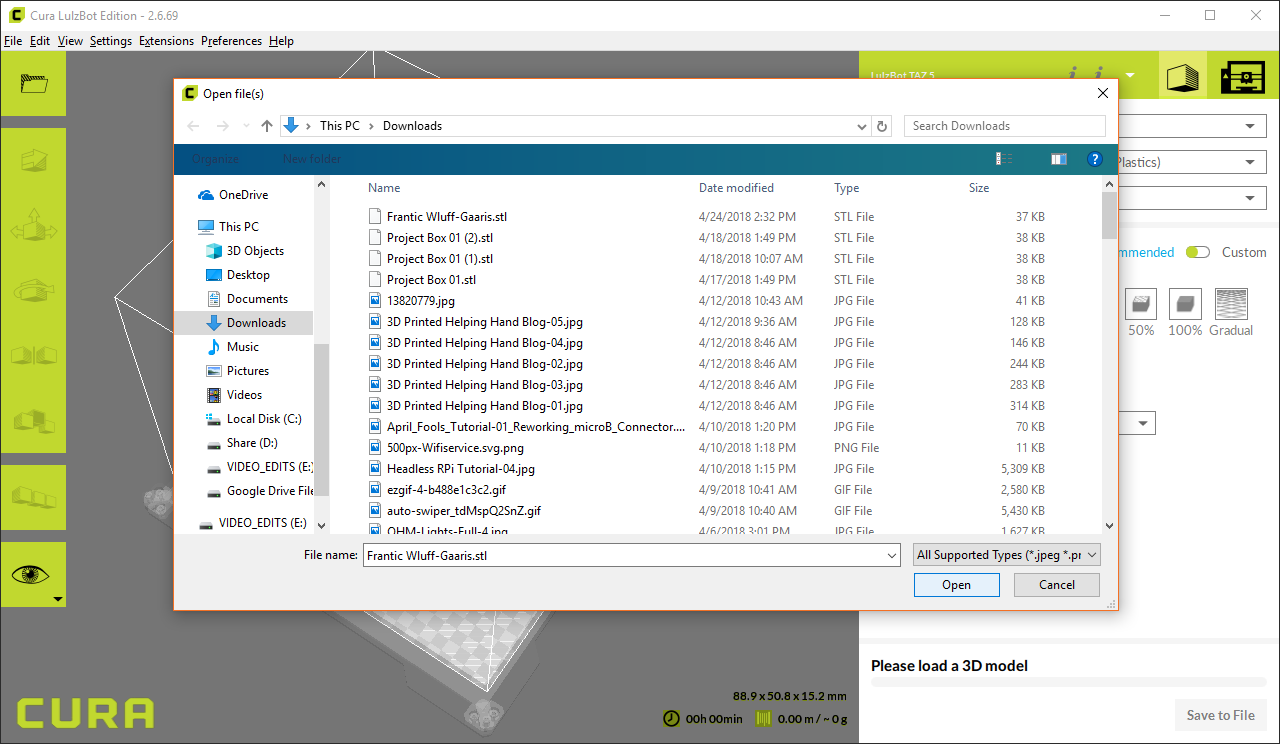
Select File > Open File(s)..., choose your exported .stl file (Frantic Wluff-Gaaris.stl for me), and click Open.
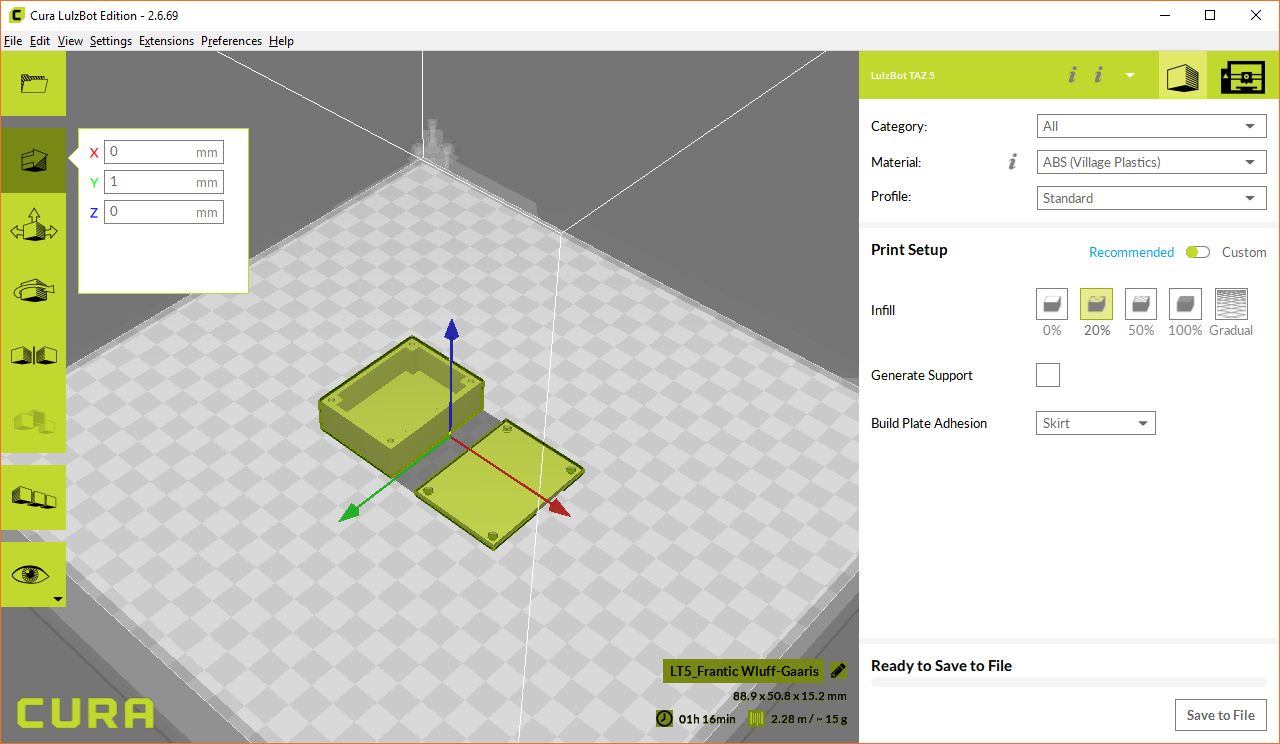
Your model should appear on the bed. Feel free to click and drag the model around to move it to a different location on the bed. This can be helpful if you want to print multiple things at once.
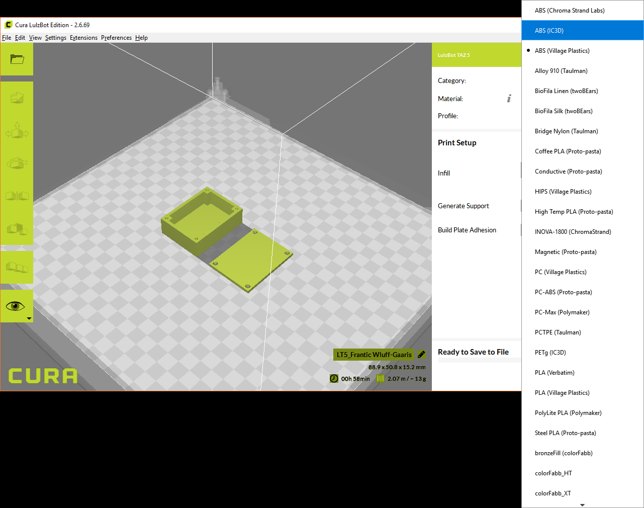
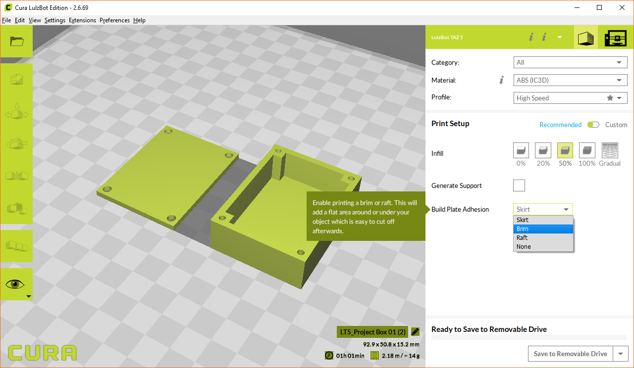
On the right side, leave Category as All. Click the drop-down menu for Material and select the type of material you are planning to use for your print. I plan to use ABS plastic manufactured by IC3D, so I'll select that.
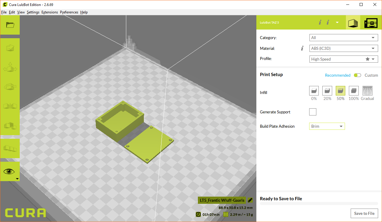
For Profile, you can leave it as High Speed, as our enclosure is really meant for functionality. You're welcome to add some aesthetics to the model and print it with Standard or High Quality, if you wish.
Because we are printing an object that is meant to accept tapping screws (e.g. the threads bite into the material), it's recommended that we print with at least 50% infill. Infill is the area inside the walls of the print (with 0%, our print would be hollow). So, select 50% for Infill.
We don't need support, so leave that unchecked. Support means that material will be added underneath the part to help support angles, overhands, and other pieces that are not flat on the bed.
You can leave Build Plate Adhesion as Skirt, but when printing with a large, flat area (like our box) and a high temperature material (like ABS), it's recommended that you select Brim. If you would like to learn more about skirts, brims, and rafts, check out this article.
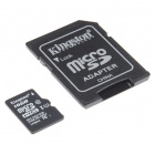
You can print to many printers directly from your computer (e.g. over USB). Without a dedicated computer attached to your 3D printer, you will need an SD card to store your machine code (at least for the LulzBot printers). For the TAZ 5, you need a full sized SD card (or a micro SD card with full sized adapter) and some way to read/write files to the SD card from your computer.
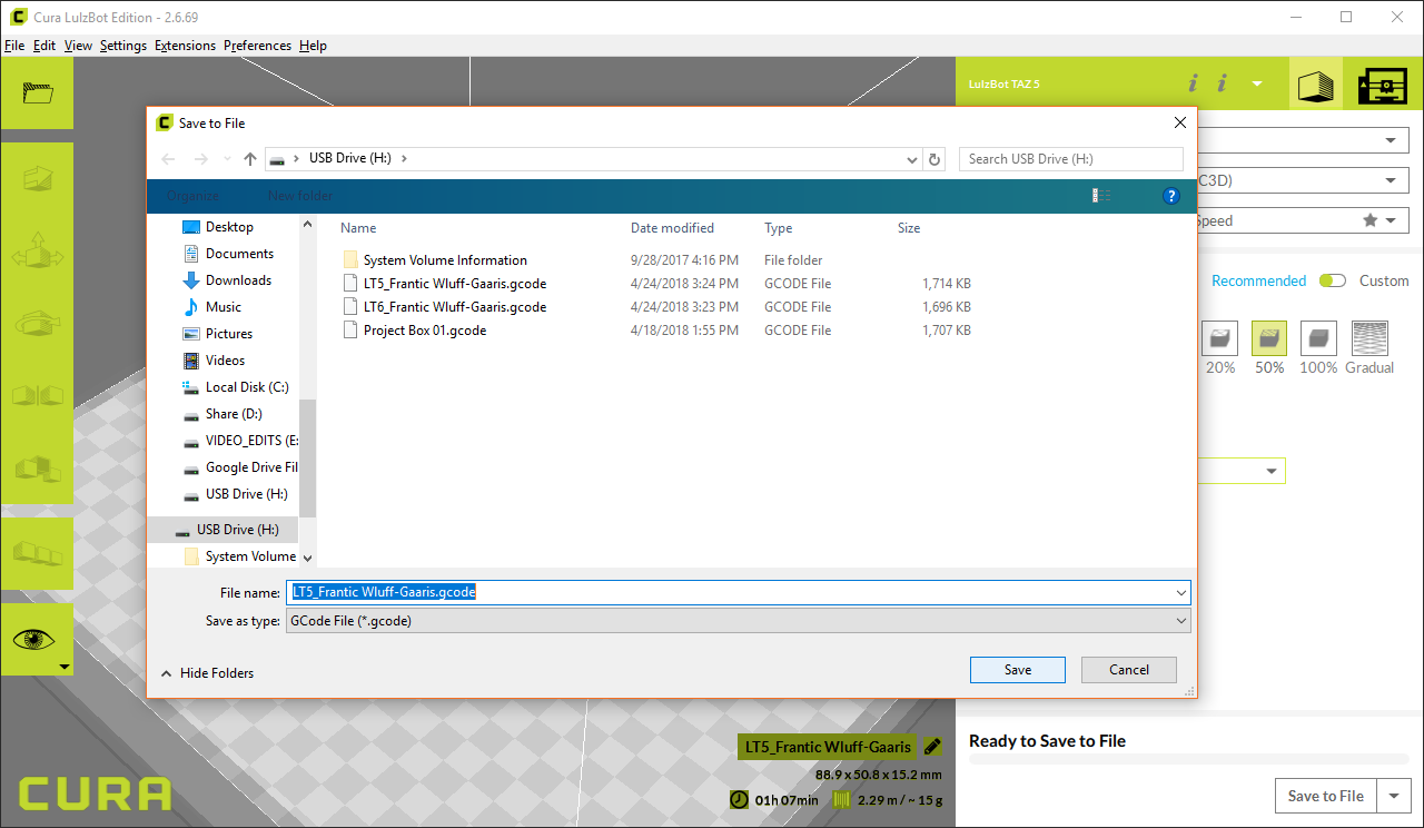
Plug the SD card into your computer, and it should enumerate as a drive. In Cura, click the Save to File button in the lower right corner. Navigate to your SD card and save the file. Remember the file name, as you'll need to select it on the printer!
With the g-code saved on the SD card, it's time to print!
Before you begin pre-heating and printing, you will want to choose a material. For this simple project, we recommend ABS or PLA. If you're curious, Nick has a great video showing you the differences among a few different types of material:
The extruder needs to reach a particular temperature in order to melt the desired material, and the bed must be heated in order to keep the material warm after it comes out of the extruder. This prevents warping in your print.
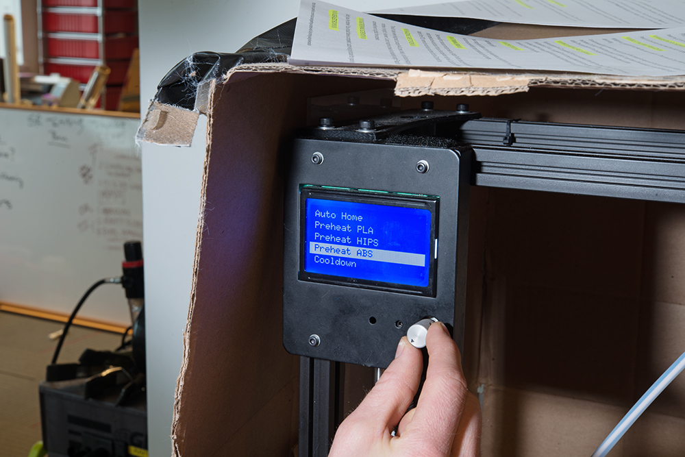
On your LulzBot TAZ, press in on the control knob to bring up the menu. Twist the knob to select Prepare, and click in again. Select Preheat PLA or Preheat ABS, depending on your material. Click in once more to begin the heating process.
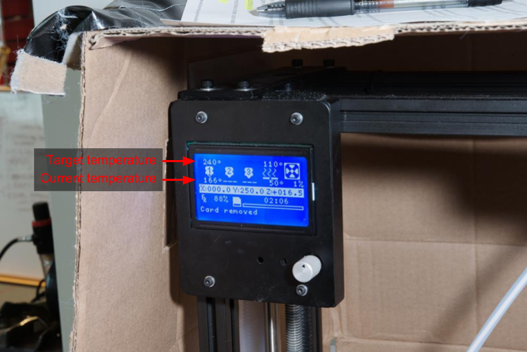
Wait 5-10 minutes while the extruder and bed reach the preheating temperature. You can look at the LCD to see the current temperature and target temperature. Once the current temperature equals the target temperature, you can move on to the next step.
Once your extruder and bed have reached the necessary temperature, you can change out the material.
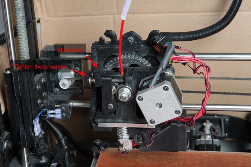
Remove the current material by gently squeezing the idler latch against the bolt heads on the extruder, and flip up the latch. Rotate the idler assembly down to allow access to the material feed on the extruder.

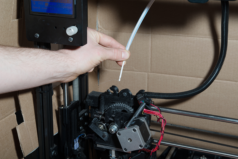
Carefully pull the filament out of the extruder.
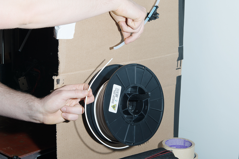
Holding the filament spool, carefully pull the material out through the feed tube, and wrap it around the spool for storage.
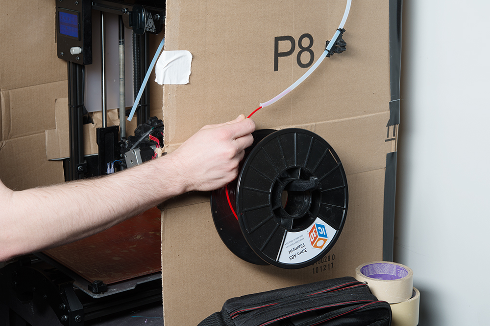
Grab the new material, and place it on the filament arm. Find the end of the spool, and feed the filament through the feed tube until it pokes out near the extruder.
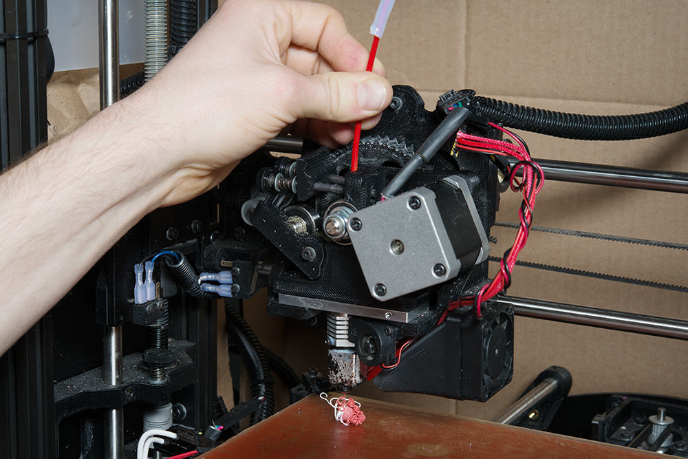
Grab the end of the filament (the part that's poking out of the feed tube), and poke it through the feed hole in the extruder. Slowly increase the amount of pressure in order to manually feed the filament through the extruder. It should melt and begin coming out of the extruder nozzle. At first, you should see the old color/material, as most extruders will retain some material even after you pulled out the filament. You might see a blending of colors. Keep pushing until the extruded material appears the same color as the new filament. This process can take 10-20 seconds.
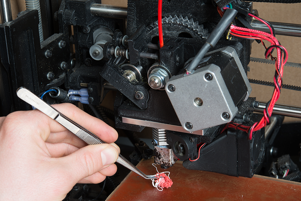
Use a set of tweezers to remove the extruded material.
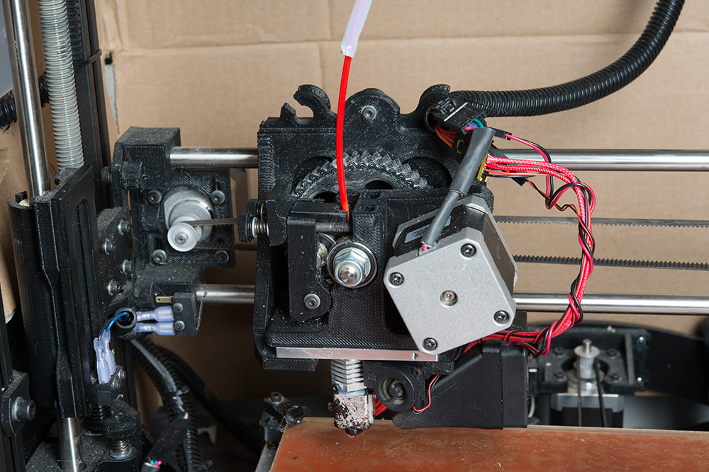
Move the idler assembly back into place (the new filament should fit into the notch in the idler). Swing the idler latch down to clamp the idler, locking it into place.
Insert the SD card into the side of the printer.
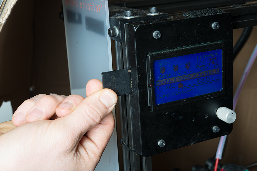
Press in on the control knob, twist the knob to highlight Print from SD, and press in again to select it.
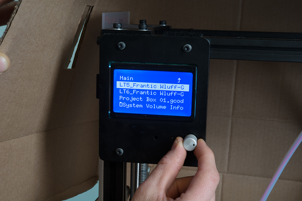
Highlight your .gcode file (verify it's the same filename that you saved from your slicer program!), and press the knob to select it. Once you do, the printer will automatically calibrate and start printing.
It's recommended that you watch the print for the first few minutes to make sure that your first layer sticks to the bed properly. Don't worry if the skirt/brim doesn't print right. It might take a few seconds for the material to begin sticking. Only cancel the print if the first layer of the actual object does not stick.

Your slicer program or the 3D printer should give you an estimate of how long it will take to print. The box we made should take around 1.5 hours. You may want to set a timer, and check back around then. After the print is done, you will want to wait a few minutes for the extruder and bed to automatically cool off. Use a a flat object, like a clam knife, to pry the part(s) off the print bed.
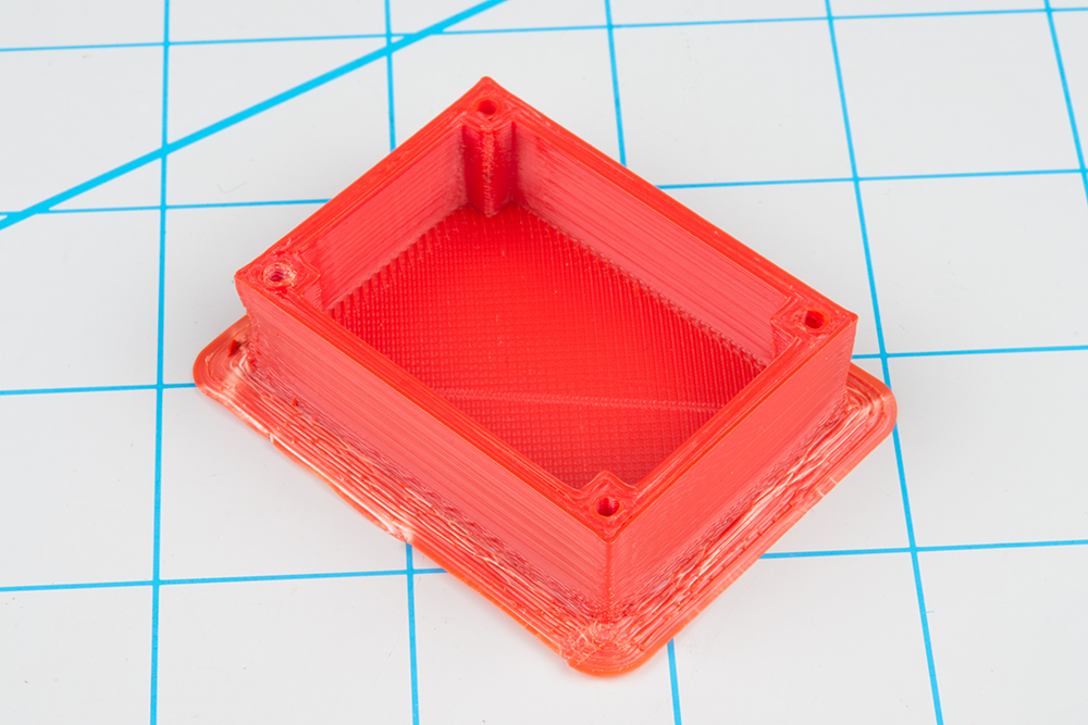
Use a hobby knife or clippers to trim off any excess pieces, such as the brim (if you printed with one). If you wish, you can use some sanding paper to smooth out any rough edges.

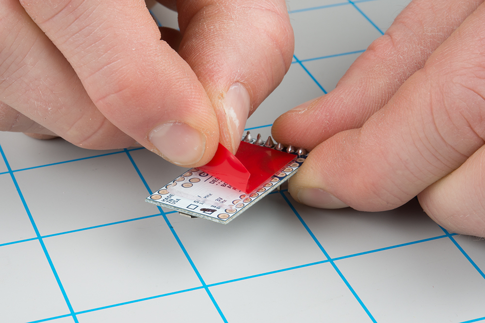
Since we did not place any mounting holes for our Arduino Pro Mini in the box, we will need to adhere the PCB using some double-sided tape or hot glue. Servo tape works really well. Cut a piece just big enough to cover the back of the PCB, remove the outer layer, and press the board into the 3D printed box (you might need more than one layer of tape if there are components or header pins sticking through the bottom side).
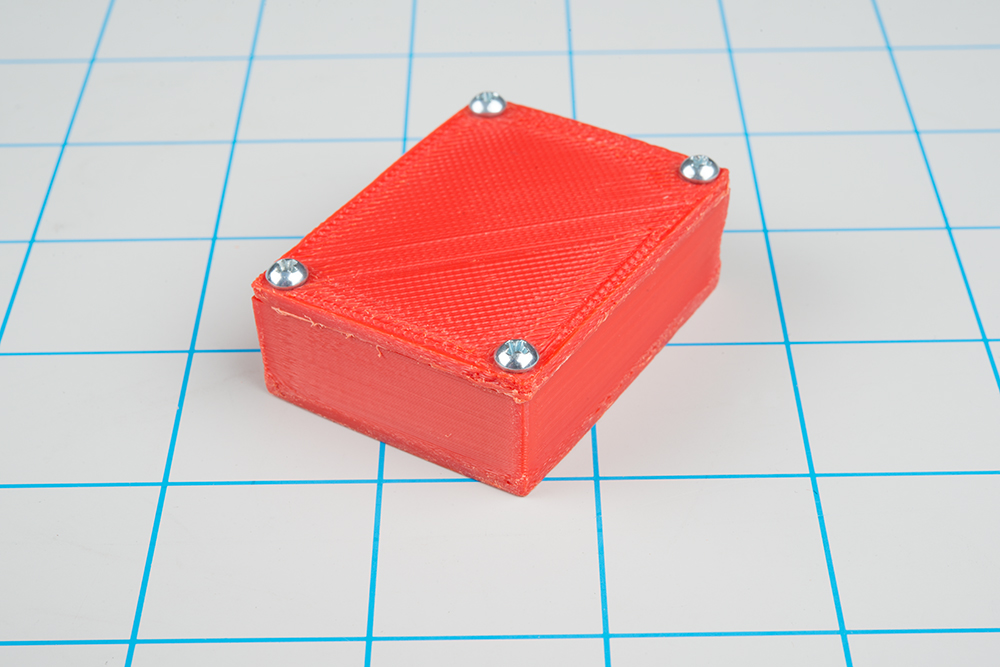
The lid holes were designed to accept #4-40 screws. Ideally, you will want self-tapping screws that are around 3/8 inches in length. However, 1/4 inch machine screws will work decently enough. Place the lid over the box and use a screwdriver to tighten the screws.

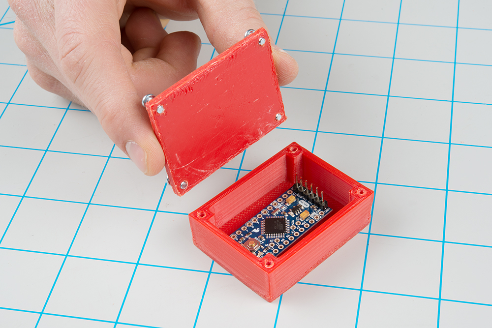
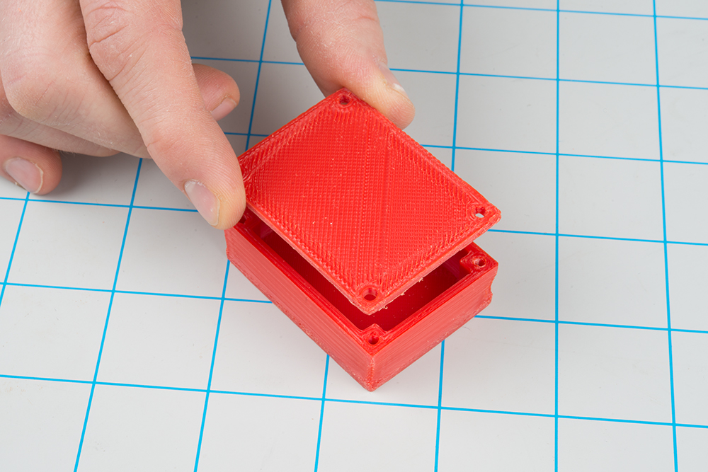
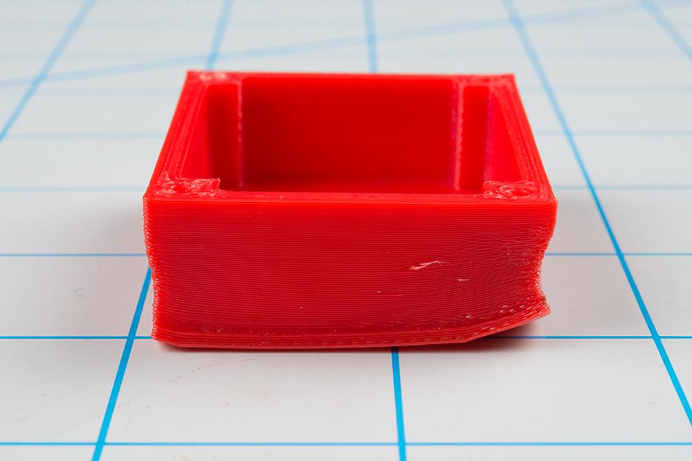
And you're done! You should have a completed, custom-designed enclosure for your electronics project.
3D printing is still a relatively new technology, and it's only just become affordable for home and classroom use. As a result, it's still not quite a push-button-get-print operation. It's only natural that some things might go wrong or that your printer requires some maintenance. Once again, please refer to the manual for your specific printer to learn how to operate it and make adjustments/repairs!
If your part has lifted corners on the bottom, it usually means that the material was cooling and shrinking. This shrinkage might be severe enough (especially on larger prints) that it pulls away from the print bed.
ABS plastic usually requires a hotter extruder to melt (vs. PLA), and as a result, is more prone to warping. You can try switching to PLA or tell your slicer program that you want to try printing with a brim (think of it like the brim of a hat) or raft.
A brim will print material around and connected to the first layer (unlike a skirt, which is not connected). This has the effect of helping the first layer stick to the bed. However, it does mean you have to trim off the brim once the print is done.
A raft will place some material underneath your part (i.e. your part is sitting on a raft of material). This should help with your part sticking to the bed even more, but it means you have even more to trim away when you're done. Rafts should be used when there is not a flat surface on the bottom of your part that will allow for good bed adhesion.
If you would like to learn more about skirts, brims, and rafts, see this article.
If you see large bubbles forming on your print bed, you will likely end up with an uneven print.
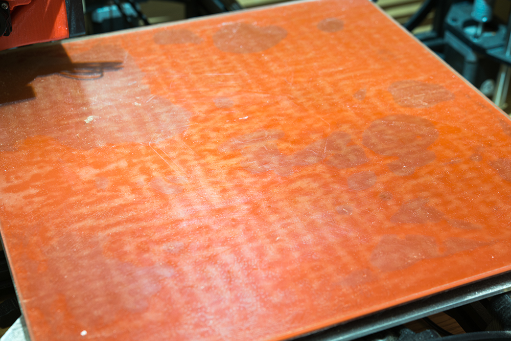
You can use something like a putty knife to try and move the bubbles after the bed has been heated, but you're only delaying the inevitable. Large bubbles usually mean that the PEI heated bed needs to be replaced. If you have a LulzBot, you can find instructions to replace the bed.
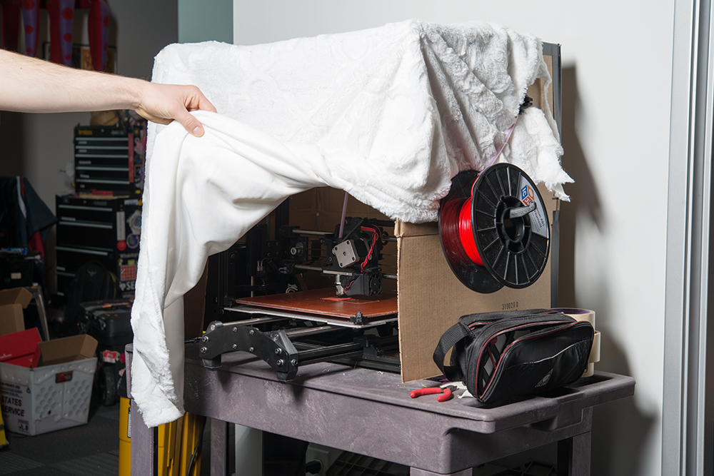
If you notice that some of the layers are not level or sticking together, you may have drafts of cool air moving through your print job. This can be fixed by moving your printer to a location away from any vents, doors, or windows. Alternatively, many 3D printing enthusiasts choose to build an enclosure around their printer to prevent any air from moving over their parts while they're being printed. It can be as simple as some cardboard or a piece of cloth.
There could be several reasons that the filament is not coming out of the extruder:
If you have just changed out the type of material and are set at a lower temperature (for example, you had ABS in the machine and you are switching to PLA), you may need to raise the temperature for the former material in order to clear out the nozzle. Pre-heat the machine for the material requiring the highest temperature (e.g. ABS requires a higher temperature to melt than PLA), manually feed the new material through to clear out the nozzle, and then reset the temperature back to that required by the new material.
If you can manually feed the material, but it is not flowing during the printing process, you may need to adjust the tension on the idler latch in order to have the printer "grip" the filament better. Simply tighten the idler latch screws slightly, and tell the machine to extrude some material (on a LulzBot TAZ 5, you can find that in the menu: Prepare > Move Axis > 1 mm > Extruder).
Found an issue that is not listed above? Besides checking the forums for your specific printer, there are websites that document common print issues. Here's one guide that we found to be quite extensive:
This tutorial was intended to give you a starting point for your 3D printing adventures, specifically how you might use 3D printed objects to enhance your electronics projects. Once you feel comfortable with Tinkercad, try making shapes and objects of your own design!
Want to get some cool 3D printing ideas? Check out these tutorials:
Or check out some of these blog posts for ideas:
learn.sparkfun.com | CC BY-SA 3.0 | SparkFun Electronics | Niwot, Colorado