This project was made in collaboration with Jeremy Cook for SparkFun Electronics.
We’re all familiar with the tried-and-true motion sensor units that turn on security lights and darken the office when no one is there and moving about. But what if you’re in the office, dutifully performing a largely sedentary job (e.g., writing an article about motion sensors)? Typical motion sensors sense… motion, as the name implies, but not human presence (which is often what you really want).
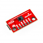
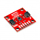
If you want a sensor that detects motion and stationary humans, the STHS34PF80 from ST Microelectronics is designed to do both. The Human Presence and Motion Sensor from SparkFun (available in both 1 x 1 inch full-sized and .5 x 1 inch mini version) breaks this chip out on a printed circuit board (PCB) for easy integration into custom projects.
This post will outline a simple human detector/alarm that you can create with this breakout, plus a handful of other parts, in under an hour. You can use it as is, or as a building block/testing setup for other projects. More resources, including SparkFun’s Hookup Guide, are linked at the end of this article.
Here are the parts used in this build:
*Note, although this project uses the STHS34PF80, we have a range of presence and distance sensors worth checking out for similar projects, like this Human Presence Sensor Breakout!
Components listed are suggested, but can be adjusted to suit. Optionally, a Qwiic Shield for Teensy can further simplify wiring.
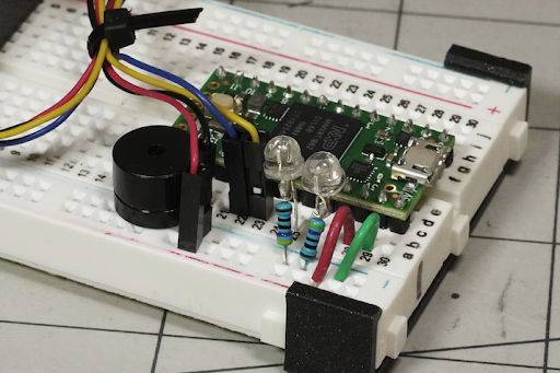
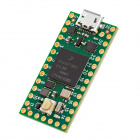
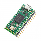
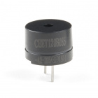
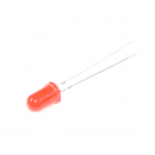
Solder header pins to your Teensy 4.0 and plug into the end of the breadboard. Jumper Ground and 3.3V from the Teensy to the rails as shown. Solder resistors to the negative leg of each LED (typically shorter, metal inside points toward positive). Connect the negative/resistor of each LED to the breadboard ground rail, and the positive to Teensy pin 22 for green (motion detected) and 21 for red (presence detected). Connect the positive speaker lead to Teensy pin 14 and the negative to the ground rail for sound output.
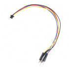
Push the Qwiic cable plug into either connector socket on the breakout board. Connect the Qwiic jumper wires to: black — ground rail, red — 3.3V rail, yellow (SCL) — Teensy pin 19, blue (SDA) — Teensy pin 18 via the breadboard.
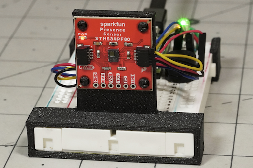
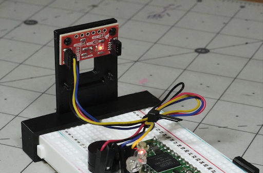
Print the fixtures and slide both onto the breadboard. Place the SparkFun sensor breakout onto the fixture’s nubs. The full-sized version is oriented facing outwards as shown in the first image on this article. The holder is reversed for the miniature version, with the sensor itself pointing into (and through) the fixture, as shown in the last image in this article.
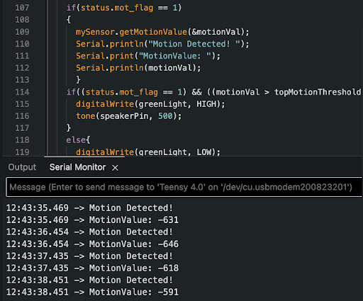
Program the Teensy with this presence-motion-sensor.ino sketch using the Arduino IDE. You’ll need the SparkFun STHS34PF80 Arduino library as outlined here. If this is your first time using the Teensy, you’ll also need to go through a few additional setup steps to get started. We recommend our Getting Started with Teensy Guide!
With the device set up and Teensy programmed, observe the alarm system’s behavior as you move or stay still in front of it. When connected to a computer via USB, open Tools > Serial Monitor on the Arduino IDE to get numerical values for presence and motion. For the light and speaker outputs, this code supplements the standard binary presence and motion flags with threshold values (presenceThreshold, topMotionThreshold, botMotionThreshold) that can be tweaked to change the device’s behavior.
This sensor package can be used with any USB power source, allowing you to implement this alarm wherever it’s convenient (e.g., use a battery pack for off-grid operation). Once you have a handle on how this presence/motion sensor works, you can modify it to suit your needs, perhaps implementing it in your next robot, presence-based lighting system, alarm, or anything else you can think of!
learn.sparkfun.com | CC BY-SA 3.0 | SparkFun Electronics | Niwot, Colorado