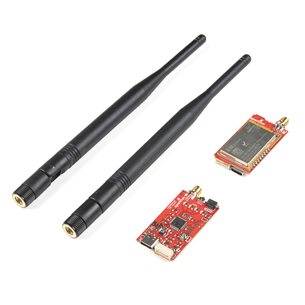
The LoRaSerial radios are simply to use radio modems that transmit over long distances (LoRa is a commonly used portmanteau of Long and Range). LoRaSerial is unique in that it makes LoRa and all the finicky radio configuration bits transparent to the user. Pull the radios out of the box, power them up, and you’ll be transmitting serial back and forth effortlessly.
We have successfully received data over 9.2 miles or 15 km line-of-sight. Your mileage will vary depending on the amount of metal, concrete, and other materials you are trying to transmit through. In general, the larger the antenna the better the range. We include ½ wave dipole antennas that have demonstrated impressive range but may be too large for your application. Any 915MHz antenna with RP-SMA termination will work.
LoRaSerial supports both Point-to-Point as well as Broadcast configurations. P2P is common and uses a transmit then wait-for-acknowledgment packet delivery system. Whereas Broadcast simply broadcasts packets without waiting for or expecting an acknowledgement. A Broadcast setup is very useful in systems where you have one ‘base’ transmitting information to multiple receivers or ‘rovers’ (common with GNSS RTK deployments).
LoRaSerial uses Frequency Hopping Spread Spectrum technology or FHSS for short. This allows any given transmission to be split up between frequencies. As you feed new serial data to the radio both transmitter and receiver will start to hop from one frequency to the next. This prevents transmissions from sitting on one frequency for too long (something called dwell time) and allows these radios to operate legally within the 915/868/433MHz* ISM band.
In the United States 433MHz operation requires a HAM radio license. 433MHz is an open band in most other countries.
LoRaSerial supports AES encryption by default as well as unique network IDs. This means that two radios will share a key and transmit any information using 128-bit AES GCM encryption. This is very strong encryption. Further, each radio is ‘paired’ (when in Point-to-Point mode) with another radio. Any packets received with the incorrect ID are ignored. This feature combined with FHSS
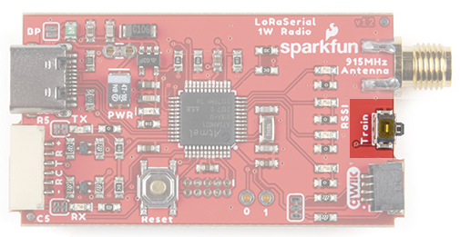
LoRa Serial uses a unique and very easy to use train feature. Each radio has a default Network ID and AES key programmed into it. Changing these keys is as easy as pressing a button! If the train button is pressed for more than 2 seconds the RSSI LEDs will begin to blink. Releasing the train button will put the unit into a ‘cylon’ mode. This indicates that the radio has chosen a new ‘random’ Network ID and AES key, as well as turned its radio down to the lowest power. Next, press and hold the train key on the second radio. Once the RSSI LEDs begin to blink, release the button. The second radio will ping the first radio. The units will then exchange new IDs and keys and immediately hop to the next frequency in the table.
Note that training uses the ‘lowest power’ radio setting. We turn the radios down to prevent any eavesdropper from obtaining the new AES keys. While these ‘new’ keys are themselves encrypted, they are encrypted using the default AES key so one could theoretically back out the new AES keys if they are within ~30ft of the devices when they are being trained. If you’re paranoid, train them with the antennas off inside a Faraday cage.
If two radios need to be paired but cannot be proximally near one another there are AT commands to support the changing of the Network ID and the AES key. If a radio is physically unreachable, a radio can be configured and even trained remotely.
The 915MHz band is used in many countries. By default, the radios will use 902 to 928MHz as allowed per the FCC in the USA. Understanding that some countries (looking at you Australia) have a narrower ISM band, the upper and lower frequencies used by the radio can be modified via AT command. Additionally, we plan to offer 868MHz (Europe) and 433MHz (longer range) based radios shortly.
Note: LoRaSerial radios currently use half-duplex serial. This means only one radio can transmit at a time. LoRaSerial was designed for applications that are predominantly one sided, meaning the base station or the remote device periodically transmits some data, and the base station receives it. This configuration is perfect for a remote weather station to transmit data or a chicken coop that needs to receive periodic commands from the house.
The LoRaSerial is a SAMD21 based assembly with a SX1276 LoRa radio with innovative firmware to make things as simple as possible.
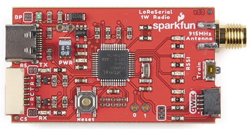
The LoRaSerial uses a 1W LoRa radio based on the SX1276 radio along with a SAMD21 utilizing the UF2 bootloader. Any serial received by the radio will be queued up, encrypted, and sent out. Any received packets are checked for CRC, Network ID, decrypted, then printed.
Note: By default there is a 50ms timeout in which the radio will wait for additional characters to be received until a partial frame is sent.
The USB C connector provides power and serial communication to the unit. LoRaSerial will automatically show up on a computer or SBC (single board computer) as a serial COM port at a default of 57600bps. Currently only 8-N-1 serial communication is supported but we are open to additional features as user’s needs arise.
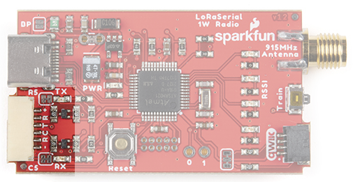
LoRaSerial features a ‘locking’ type 6-pin JST connector. The connector on LoRaSerial is X and mates with a connector JST-GHR-06V. Each LoRaSerial radio comes with a JST to breadboard friendly pins. If you need additional cables they are available here (Note: the wire color may be different between cables).
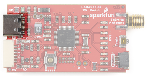
The pinout is as follows:
PWR (3.3-5V) - LoRaSerial requires 3.3 to 5V to operate. We recommend 5V for maximum transmission range but we’ve found operating off of a LiPo at 3.7 to 4.2V works great.
RX (Receive) - Connect this pin to the TX pin of your system. This pin is 3.3-5V tolerant and has an internal pull-up.
TX (Transmit - Connect this pin to the RX pin of your system. This pin uses 3.3V logic.
CTS (Clear To Send - (Optional) Connect this pin to a GPIO of your system. This pin is 3.3-5V tolerant and has an internal pull-up. When this pin is high the radio will continue to send data. If the host system pulls this pin low, the radio will stop sending data.
RTS (Ready To Send) - (Optional) Connect this pin to a GPIO of your system. This pin uses 3.3V logic. If the radio’s buffer (size currently is 4096 bytes) becomes full the system will drive RTS low indicating that it should not be passed more data. If more serial data is received, the buffer will be overwritten, oldest data first.
GND (Ground) - Connect this pin to the ground of your system.
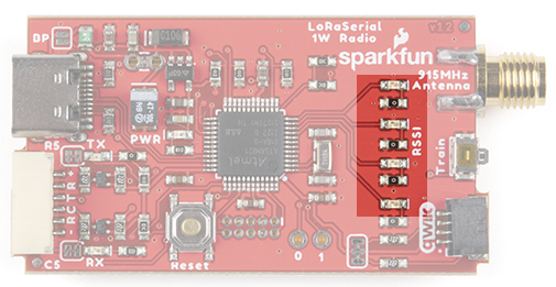
There are four LEDs indicating in real-time the received signal strength or RSSI. These LEDs are meant to indicate a qualitative level of receive strength. Don’t worry if you’ve got three LEDs rather than four. LoRa technology is capable of transmitting a long range in harsh RF conditions. As long as you’ve got one LED, you will be able to send and receive data.
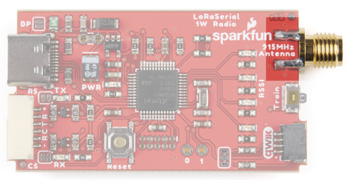
Attach a 915MHz RPSMA antenna to this port. Not sure which is SMA and which is RPSMA? Checkout this RF Connector Guide. The LoRaSerial is also compatible with large, LoRa type antennas. We recommend a good thick RG58 RPSMA extension from the radio to your antenna to minimize loss. Remember, we are transmitting at 1W so keep your cables and connectors to a minimum.
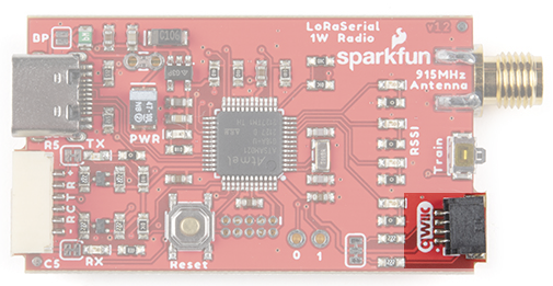
The Qwiic connector and I2C accessibility is not yet implemented.
LoRa Serial uses a unique and very easy to use train feature. Each radio has a default Network ID and AES key programmed into it. Changing these keys is as easy as pressing a button!
Using a ball point pen or other small pointed device, press and hold the Train button for 2 seconds, until you see the RSSI LEDs begin to blink. You can release the button. If the LEDs begin to cylon (bounce back and forth) the device has entered training ‘wait’ mode where it waits for another device to ping it.
On the second radio, press and hold the Train button for 2 seconds, until you see the RSSI LEDs begin to blink. Release the button. The RSSI LEDs on both units will blink in unison indicating that the units are now trained to each other.
For security reasons the radios are both set to the lowest transmission power to minimize any eavesdropper from monitoring the transaction. While the ‘new’ keys are themselves encrypted, they are encrypted using the default AES key so one could theoretically back out the new AES keys if they are within ~30ft of the devices when the radios are being trained. If you’re paranoid, train the radios with the antennas off, within a few inches of each other. If total security is a concern, or if the radios cannot be physically brought near one another, the AES keys and/or the network IDs can be set via software commands.
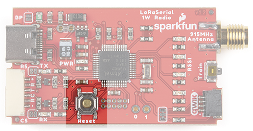
The firmware on the LoRaSerial can be upgraded from a computer without ever having to open the unit. In the rare case that the SAMD21 needs to be forced into bootloader mode the reset button should be quickly double tapped. The unit will then enter bootloader mode and wait for new firmware or for a reset event (button is pressed or power is cycled).
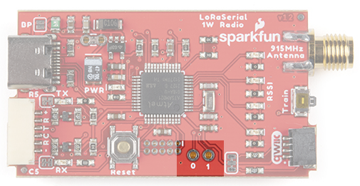
Two GPIOs capable of ADC are broken out for potential future use.
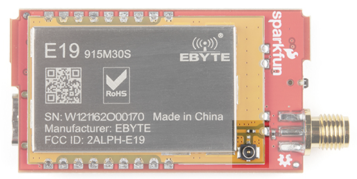
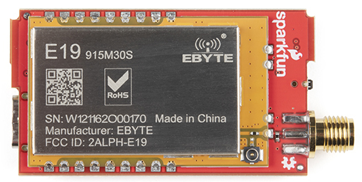
For advanced users, the 915/868MHz modules feature a U.FL connector. This can be helpful if you need to embed the radio in an enclosure and need an external bulkhead RP-SMA connector. To use the U.FL connection, desolder the 0402 0Ω jumper and move it to the U.FL's RF path.
LoRaSerial radios are very flexible. By default the radio is looking for serial communication at 57600bps. Open the terminal of your choice and enter +++ and wait for an OK. The radio is now ready for an AT command.
Below is a brief list of commands:
| AT Command | Command Description |
|---|---|
| +++ | Enter command mode |
| AT | Reports OK |
| ATI | Show board variant, firmware |
| ATI0 | Show all user settable parameters |
| ATI1 | Show board variant |
| ATI2 | Show firmware version |
| ATI3 | Display latest RSSI |
| ATI4 | Generate random byte based on RSSI |
| ATI5 | Show max possible bytes per second |
| ATI6 | Show AES Key Values |
| ATI7 | Show FHSS Channel |
| RTI? | Show equivalent remote setting |
| ATO | Exit command mode |
| ATZ | Reboot the radio |
| AT&W | Write current parameters to EEPROM |
| AT&F | Reset all parameters to factory defaults |
| AT&T=RSSI | Show RX packet RSSI, SNR, and FreqError |
| ATT | Enter Training Mode |
| ATF | Enter Training Mode with Defaults |
| ATSn? | Display a parameter |
| ATSn=X | Set a parameter |
| RTSn? | Display remote parameter |
| RTSn=X | Set remote parameter |
For a PDF of the AT commands, click here.
The main user settable parameters are listed below and available here in PDF format. A parameter is set using the ATSx command. For example sending ‘ATS21=1’ will enable debug printing. This setting can be stored in NVM (non-volatile memory) by sending the ‘AT&W’ command.
Remote configuration is supported. If two radios are linked, all AT commands can be sent to the remote radio using the RT equivalent (ie, RTZ will reboot the remote radio). Be careful as it is very possible to break the link. For example, setting the remote AES key should be done first before setting the local AES key.
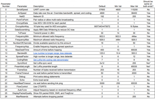
The table of common parameters is available here in PDF format.
SerialSpeed - Controls the baud rate in bits-per-second used over the UART connector. Data sent over USB will be sent/received regardless of this setting. Default is 57600bps. Allowed values are 2400, 4800, 9600, 14400, 19200, 38400, 57600, and 115200bps.
AirSpeed - This is the effective rate in bits-per-second at which data is sent over the air. In general, the lower the air speed, the greater the transmission distance. LoRaSerial uses large 4,000 byte buffers to receive and send serial over USB or UART at the SerialSpeed and begins sending that data in chunks over the air at the AirSpeed. The AirSpeed setting does not have to match the SerialSpeed. It is recommended to limit the total incoming data to match the AirSpeed. For example, regularly sending a group of 300 bytes with an air speed of 4800 bps (480 bytes per second) will allow the radio sufficient bandwidth. Sending 1,000 bytes per second with an air speed of 4800 bps (480 bytes per second) will within a few seconds overwhelm the link leading to buffer overflow and data loss. Default is 4800bps. Allowed values are 0, 40, 150, 400, 1200, 2400, 4800, 9600, 19200, 28800, and 38400 bits per second. 0 is a special value that allows the Bandwidth, SpreadFactor, and CodingRate settings to be used instead.
NetID - In PointToPoint mode each radio is paired with another radio. They will have unique frequencies that they will use. However, crosstalk is always possible. If a packet is received with a non-matching NetID it is discarded. Changing the NetID is a handy way to make sure your radio pair does not interfere with another pair of radios in the same vicinity.
PointToPoint - In point to point mode, two radios pass packets and acknowledge (confirm) the receipt of a given packet. Lost packets are automatically retransmitted up to MaxRends number of tries. When PointToPoint is turned off, acknowledgements are turned off. Any radio using the same settings will be able to receive packets from each other. This is most useful when you have one ‘base’ transmitter with multiple ‘rovers’ receiving that data.
EncryptData - By default all packets are encrypted using 128 bit AES GCM. Disabling this will not get greater range or bandwidth. Disabling encryption will allow all packets to be seen in clear text via an SDR or other monitoring device.
EncryptionKey - This is the 16 byte key used for AES encryption. While this can be set via command, we recommend using the train feature as this is much faster and less error prone.
DataScrambling - Enabling data scrambling will send all packets through an IBM data whitening process. This removes long sets of 1s or 0s from the packet to reduce DC bias during transmission. This is generally not needed and is not recommended when AES encryption is enabled. By default scrambling is turned off.
TxPower - The LoRaSerial uses a high power 1W transceiver. By default, all transmissions are sent at the highest possible power of 30dBm which is compliant with FCC Part 15.247 when used with an antenna that has a gain of 6dBi or less. If your local regulations require lower transmission power this setting can be lowered. Allowed values are 30 down to 14dBm. Note: The chosen setting is the actual measured transmit power at the SMA connector. An internal lookup table sets the radio settings accordingly.
FrequencyMin/FrequencyMax - These are the lower and upper bounds for the allowed transmission frequencies in megahertz. By default this is 902.0 to 928.0.
NumberOfChannels - The available spectrum (default is 902MHz to 928MHz) is divided by this number of channels to create the channel spacing and allowed frequency list (aka the ‘hop table’). The default is 50 channels to meet FCC Part 15.247 compliance and may be changed to meet local regulations.
FrequencyHop - The LoRaSerial implements frequency hopping spread spectrum (FHSS) by default to meet FCC Part 15.247 compliance. Turning off frequency hopping is not recommended unless You Know What You’re Doing™.
MaxDwellTime - The number of milliseconds of transmission allowed on a given frequency before hopping intra-packet. The default is 400ms to be compliant with FCC Part 15.247. This means the radio will change its frequency to the next channel in the hop table during the packet transmission. Note this is the maximum dwell time; depending on the air speed setting the radio may have a hopping period that is shorter than the dwell time.
Bandwidth - The bandwidth used around a given frequency during LoRa transmissions. Setting is in kHz. This setting is overwritten if the AirSpeed setting is non-zero. It is recommended to use the air speed setting unless you are very aware of the consequences. Change AirSpeed to 0 to use a custom bandwidth. In general a lower bandwidth number provides longer range, but lower overall data rate. Allowed bandwidths: 10.4, 15.6, 20.8, 31.25, 41.7, 62.5, 125.0, 250.0, and 500.0kHz.
SpreadFactor - The spread factor used during LoRa transmissions. It is recommended to use the air speed setting unless you are very aware of the consequences. This setting is overwritten if the AirSpeed setting is non-zero. Change AirSpeed to 0 to use a custom spread factor. In general a higher spread factor provides longer range, but lower overall data rate. Allowed spread factors: 6 to 12 (inclusive).
CodingRate - The coding rate used during LoRa transmissions. It is recommended to use the air speed setting unless you are very aware of the consequences. This setting is overwritten if the AirSpeed setting is non-zero. Change AirSpeed to 0 to use a custom coding rate. In general a higher spread factor provides longer range, but lower overall data rate. Allowed spread factors: 6 to 12 (inclusive).
SyncWord - The byte used to synchronize LoRa transmissions. In general this is set to 0x12 for non-LoRaWAN networks. Note that two LoRa radios with the same settings but different sync words have been shown to intermittently receive packets from each other. Therefore, using a unique synch word does not guarantee exclusivity. Allowed values: 0 to 255.
PreambleLength - The number of sync words to send at the start of a packet. Note that two LoRa radios with the same settings but different preamble lengths have been shown to intermittently receive packets from each other. Therefore, using a unique preamble length does not guarantee exclusivity. Allowed values: 6 to 65535.
FrameSize - The number of bytes to be received before initiating a transmission. The default is 253. Allowed values: 16 to 253.
FrameTimeout - The number of milliseconds of timeout before a partial packet is sent. For example if a partial frame of 12 bytes are received, the radio will wait this amount for more bytes before initiating a transmission. The default is 50ms. Allowed values: 10 to 2000ms.
Debug - Enabling debug messages will print additional information about the radio’s state and packet information. Default is off.
Echo - By default the radio will not echo the incoming serial. This is helpful at times if a user is typing data directly into a terminal. During AT configuration echo is turned on regardless of this setting.
HeartBeatTimeout - When PointToPoint mode is enabled, a radio will send a ping packet every HeartBeatTimeout number of milliseconds if there is no data traffic. The default is 5000ms (5 seconds). Allowed values: 250 to 65535ms.
FlowControl - If flow control is enabled, the radio will not print data if CTS is low (host is telling the radio to hold its horses). If flow control is enabled, the radio will pull RTS low if its serial buffer is full (radio is telling the host to hold its horses). CTS and RTS pins are only exposed on the UART connector but apply to both USB and serial data streams. By default, flow control is turned off. Internal pullups are used so RTS and CTS can be left floating if not used.
AutoTune - Based on the frequency error of the last received packet, tune the receive frequency accordingly. Currently, this feature is not recommended. Default is off.
DisplayPacketQuality - Show RSSI (received signal strength indicator), SNR (signal to noise ratio), and FreqError (frequency error) for all received packets.
MaxResends - If PointToPoint is enabled, a radio will transmit a data packet and then wait for a response. If no response is received within 125% of the response packet’s air time, the data will be resent up to MaxResends. Default is 2. Allowed values: 0 to 255.
The LoRaSerial uses a novel technique for generating the frequencies it uses for transmission. In order to prevent other radios and other LoRaSerial products from transmitting over each other a unique hop table must be generated. To achieve this, a unit’s settings needed for a working link are combined into a 16 bit number that is used as a random seed. A table, based on the min/max frequencies and the number of channels, is then randomly sorted using the random seed. This guarantees that two radios, even with slightly different settings, have very different hop patterns.
The following table shows the relationship between the AirSpeed setting and the resulting LoRa specific bandwidth, spread factor, and coding rates. In general, it is recommended that users use AirSpeed and to not use custom bandwidths, spread factors, or coding rates as this may lead to out-of-compliance setups.
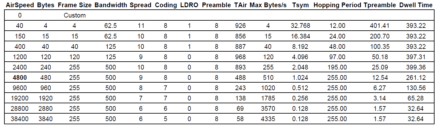
The bandwidth, spread, and coding rates were chosen to get close to an ‘equivalent’ commonly used baud rate. However this is not absolute. An airspeed of 4800 bits per second is default but as can be seen in the table, the actual max bytes per second is approximately 510 best case scenario.
We hope you enjoy using the LoRaSerial as much as we have!
Here are the pertinent technical documents for the LoRaSerial:
Check out these additional tutorials for your perusal:
learn.sparkfun.com | CC BY-SA 3.0 | SparkFun Electronics | Niwot, Colorado