The Breadboard Power Supply Kit allows your breadboard projects to easily access a selectable voltage regulated to either 3.3Volts or 5Volts. It receives its power through a DC wall wart like this one. Any stripped +/- DC supply can also be connected instead of the barrel connector if desired. This guide will help with everything you need to get started with the Breadboard Power Supply.
This kit comes as a bag of parts and requires assembly with the use of a soldering iron and requires you to solder all the parts onto the printed circuit board yourself. You will need a few tools to be able to do this. Following is a list of recommended tools and assembly parts:
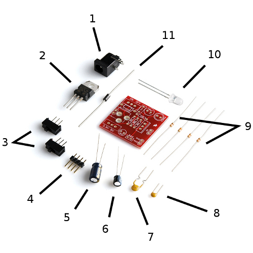
Use the links above and the image below to identify any parts you are unfamiliar with. The numbers in the list above correlate with the numbers in both the images below to help you with assembly.
With some beginning experience in soldering, assembly should be rather straightforward. If this is your first time soldering, we recommend taking a look at our through-hole soldering tutorial
All the parts are to be soldered to the top of the board (the side with the silkscreen writing) with the exception of the headers. The .1" headers are mounted on the bottom of the PCB for simple insertion into a breadboard. We will assemble the kit in the order listed above. However, take note that the parts can technically be soldered in any order, and often times, the easiest method is to start with the smaller components on the top (resistors, diode, small caps, etc.), then moving on to the larger components (voltage regulator, barrel jack, etc.) For this board though, it's not a huge concern because there is enough working room regardless of the order you choose. The whole process is estimated to take 30 minutes but varies based on your soldering skill level. Here is a photo of the PCB for reference:
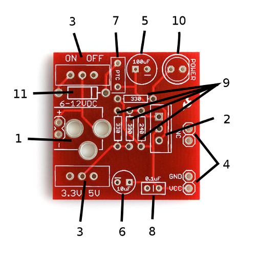
Keep in mind the numbers of each part in the part list above matches the two images labeled with numbers as well as the instructions below. This should allow you to easily figure out what item needs to be soldered where.
Use wire cutters to snip any extra leads and if you accidentally soldered something into the wrong place, use solder wick to get rid of the solder, replace the component, and solder again. If you've never done something like that before, it's worth it to check out our soldering tutorials beforehand.
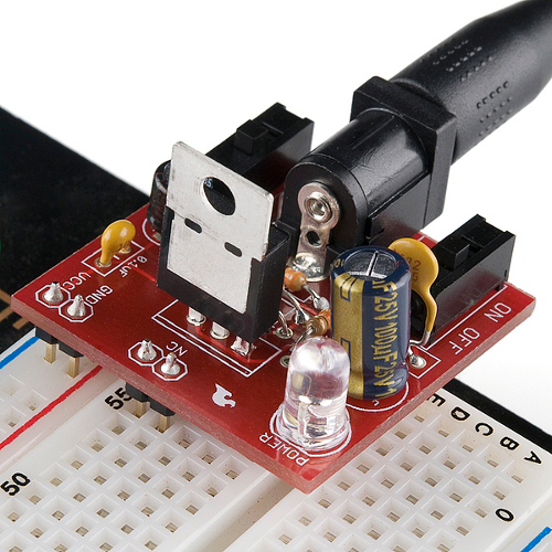
After it's all soldered, it's time to plug it into the breadboard. Line up the the VCC and GND header pins with the power rails on the breadboard. The other two header pins should fit into the breadboard as well as shown in the first photo. These two extra pins are only there for physical support and don't have any electrical connection on the PCB. Reference the photograph below if needed.
All that's left is connecting the wall wart to the barrel jack, selecting which voltage you want via one of the switches and using the other switch to turn it on. The red LED should light up. Careful, it's bright. Double check each voltage setting with a multimeter to make sure the proper voltage is being applied to the breadboard (3.3V or 5V depending on the switch settings).
Well, now that you have the power, it's time to build some circuits! Always feel free to share your projects with us!
learn.sparkfun.com | CC BY-SA 3.0 | SparkFun Electronics | Niwot, Colorado