SparkFun Triple Axis Accelerometer Breakout - BMA400 (Qwiic) Hookup Guide
 El Duderino
 Introduction
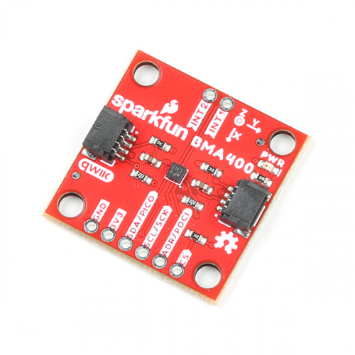
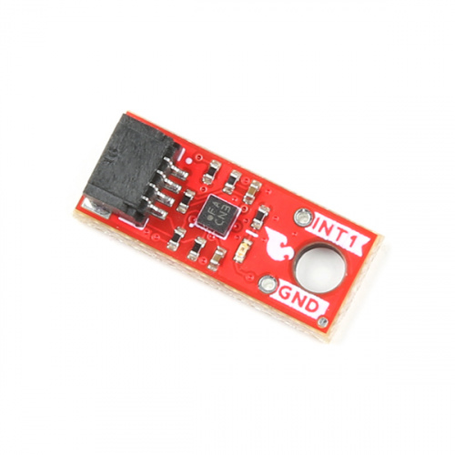
The SparkFun Triple Axis Accelerometer Breakout - BMA400 (Qwiic) (Standard and Micro) offer a 3-axis acceleration sensor perfect for ultra low-power applications on a easy to use Qwiic breakout boards. The Qwiic system allows for integration into your I2C system with no soldering required. The standard size Qwiic breakout also includes 0.1"-spaced PTH pins connected to the sensor's communication interface and interrupt pins for applications that require a traditional soldered connection.
The BMA400 from Bosch Sensortech© has a full scale acceleration range of ±2/±4/±8/±16g with exceptionally low current consumption of < 14.5µA while operating at its highest performance settings. The sensor also includes a complete feature set for on-chip interrupts including step counter, activity recognition, orientation detection and tap/double tap.
This guide will go into detail on the features of the BMA400 and hardware on these boards as well as how to integrate it into a Qwiic circuit using the SparkFun BMA400 Arduino Library.
Required Materials
To follow along with this guide you will need a microcontroller to communicate with the BMA400. Below are a few options that come Qwiic-enabled out of the box:


If your chosen microcontroller is not already Qwiic-enabled, you can add that functionality with one or more of the following items:


You will also need at least one Qwiic cable to connect your sensor to your microcontroller.


Suggested Reading
If you aren't familiar with the Qwiic system, we recommend reading here for an overview.
We also recommend taking a look at the following tutorials if you aren't familiar with the concepts covered in them. If you are using one of the Qwiic Shields listed above, you may want to read through their respective Hookup Guides as well before you get started with the SparkFun Triple Axis Accelerometer Breakout - BMA400 (Qwiic).
Serial Terminal Basics
Qwiic Shield for Arduino & Photon Hookup Guide
SparkFun Qwiic Shield for Arduino Nano Hookup Guide
Hardware Overview
Let's take a closer look at the BMA400 and other hardware features on these Qwiic breakouts.
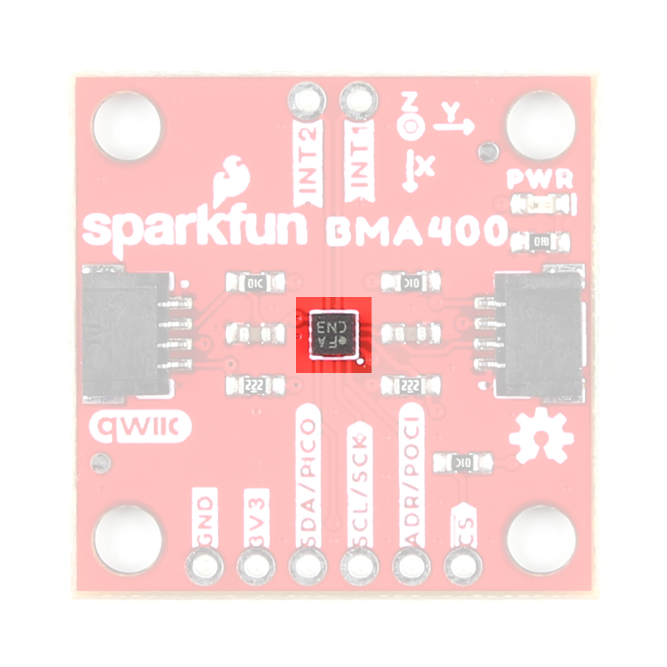
BMA400 3-Axis Accelerometer
The BMA400 3-axis accelerometer from Bosch Sensortec is an ultra-low power motion sensor with a host of interrupt features making it ideal for battery-powered activity monitoring applications.
 |
 |
The BMA400 features four user-selectable ranges of ±2/±4/±8/±16g and consumes just 14.5µA when measuring acceleration data at the highest performance settings. The BMA400 also includes a robust interrupt feature set:
- Auto Wakeup
- Auto Low Power
- Step Counter
- Activity Recognition (Running, Walking, Standing Still)
- Orientation Detection
- Tap and Double Tap
The sensor has two interrupt pins available for all of the above interrupt conditions. The table below outlines a few of the BMA400's sensing and operating parameters. For a full overview of the BMA400, refer to the datasheet.
| Parameter | Min. | Typ. | Max. | Units | Notes |
|---|---|---|---|---|---|
| Supply Voltage | 1.72 | 1.8 | 3.6 | V | Breakouts run BMA400 at 3.3V. |
| Normal Mode Current Draw | 14.5 | µA | Oversampling Rate set to 3 | ||
| Low-Power Mode Current Draw | 0.850 | Oversampling Rate set to 0 | |||
| Sleep Mode Current Draw | 0.160 | ||||
| Acceleration Range | ±2 | g | Sensitivity of 1024LSB/g | ||
| ±4 | Sensitivity of 512LSB/g | ||||
| ±8 | Sensitivity of 256LSB/g | ||||
| ±16 | Sensitivity of 128LSB/g | ||||
| Output Data Rate (ODR) | 12.5 | 800 | Hz | ODR in Low-Power mode is 25Hz |
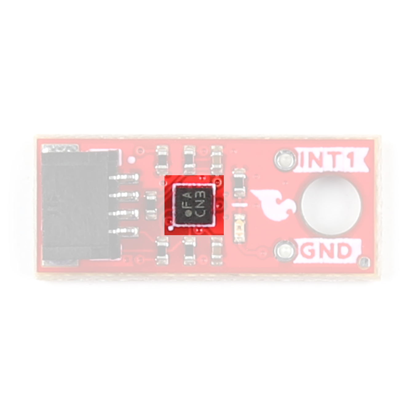
Communication Interfaces - I2C & SPI
The standard size version of these Qwiic breakouts communicates over I2C by default but also supports communicating using SPI. The Qwiic Micro version only supports I2C communication over the Qwiic connector on the board.
 |
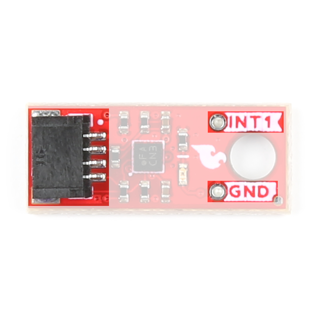 |
The standard size routes the I2C interface to a pair of Qwiic connectors as well as a 0.1"-spaced PTH header for users who prefer SPI or a traditional soldered connection. The standard-size breakout routes both INT1 and INT2 to a pair of PTH pins. The Qwiic Micro routes only INT1 to a PTH pin.
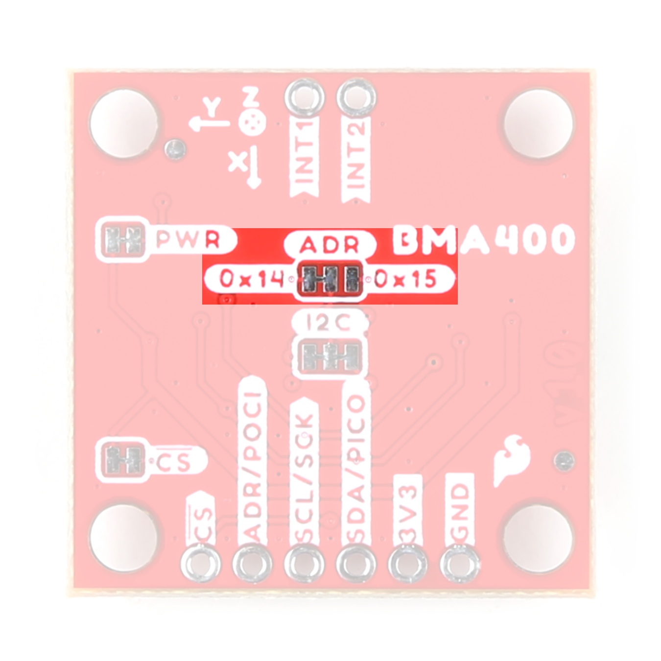
Both boards set the BMA400's I2C address to 0x14 by default. Adjust the ADR jumper to change to the alternate address (0x15) or open it completely to use the SPI interface (Standard size only). More information on this jumper in the Solder Jumpers section below.
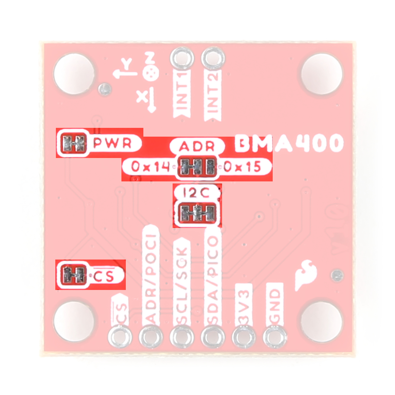
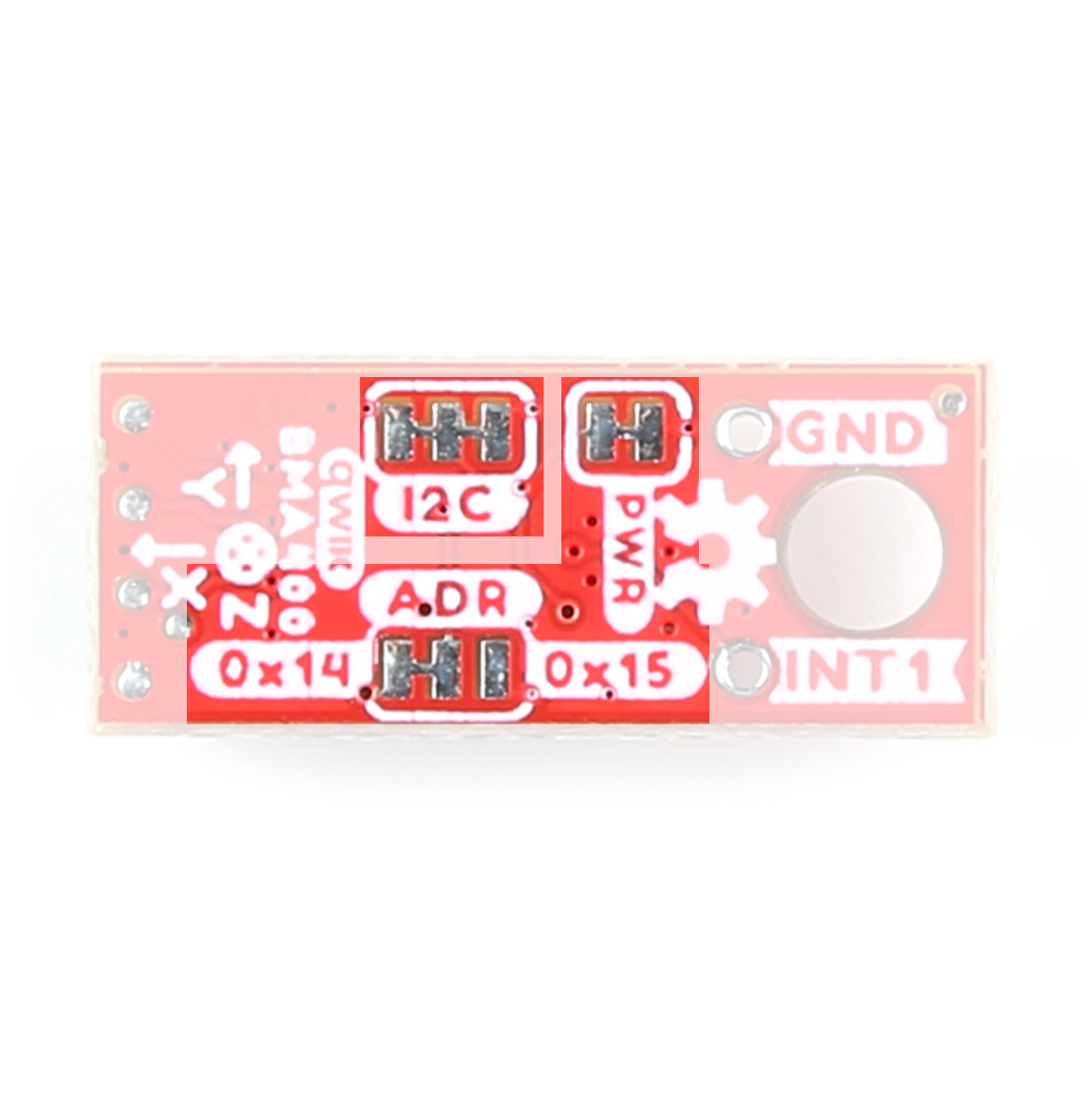
Solder Jumpers
The Standard size breakout has four solder jumpers labeled PWR, ADR, I2C, and CS. The Micro size has all but the CS jumper as the Micro version does not support SPI. Instead, the Micro version pulls the CS pin to 3.3V. The table below outlines the jumpers' labels, default state, functionality, and any notes regarding their use.
 |
 |
| Label | Default State | Function | Notes |
|---|---|---|---|
| PWR | CLOSED | Completes the Power LED circuit. | Open to disable the Power LED. |
| ADR | SEE NOTE | Sets the sensor's I2C address. | Address is 0x14 by default. Switch to 0x15 by severing the trace between the "Center" and "Left" pads and connecting the "Center" and "Right" pads. Leave open entirely to use the BMA400 over SPI (Standard size only.) |
| I2C | CLOSED | Ties the SDA/SCL lines to VCC (3.3V) through a pair of 2.2kΩ resistors. | Open the jumper to disable the pull-up resistors on the I2C lines. |
| CS* | CLOSED | Pulls the BMA400's chip select (CS) pin to VCC (3.3V) through a 10kΩ resistor. | *Standard size only. Open to disable the pull-up on CS. |
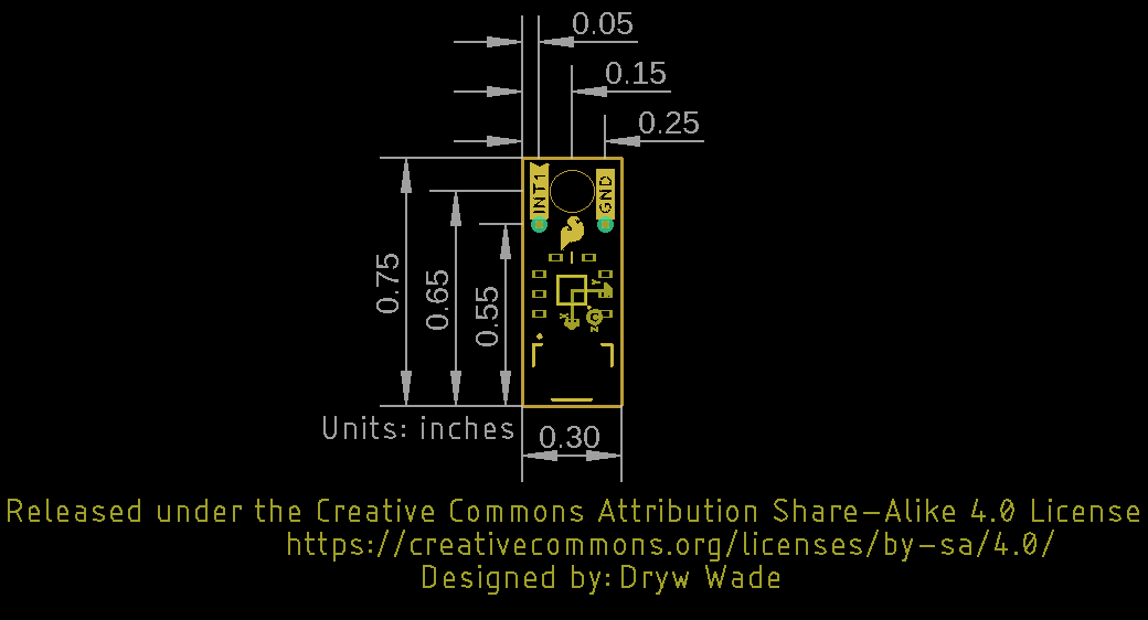
Board Dimensions
The boards match the Standard and Micro form-factors for Qwiic breakouts measuring 1" x 1" (Standard) and 0.5" x 0.3" (Micro). The Standard breakout has four mounting holes and the Micro has one. All mounting holes fit a size 4-40 screw.
 |
 |
Hardware Assembly
Now that we're familiar with the BMA400, we can start assembling our circuit.
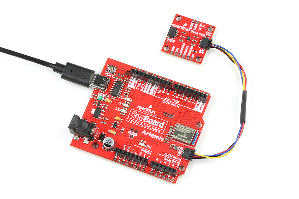
Qwiic/I2C Assembly
The fastest and easiest way to get started using the breakout is to connect the Qwiic connector on the breakout to a Qwiic-enabled development board like the SparkFun RedBoard Artemis with a Qwiic cable and as shown in the image below.
If you would prefer a more secure and permanent connection with the Standard Size breakout, you can solder headers or wire to the PTH header on the board.
SPI Assembly (Standard Size Only)
Setting the breakout up to communicate with the sensor over SPI requires completely opening the ADR jumper and we recommend soldering to the PTH header to make the connections. If you are not familiar with through-hole soldering, take a read through this tutorial:
How to Solder: Through-Hole Soldering
September 19, 2013
Along with tools for soldering, you'll need either some hookup wire or headers and jumper wires. Sever the trace between the "Center" and "Right" pads of the ADR jumper to switch to SPI mode. After opening this jumper, connect the breakout to your controller's SPI bus pins.
Remember, the BMP384 operates at 3.3V logic so make sure to connect to a board running at the same logic level like the RedBoard Artemis or use a level shifter to adjust it to the correct voltage.
BMA400 Arduino Library
Note: This library assumes you are using the latest version of the Arduino IDE on your desktop. If this is your first time using Arduino, please review our tutorial on installing the Arduino IDE. If you have not previously installed an Arduino library, please check out our installation guide.
The SparkFun BMA400 Arduino Library is based off the API for the sensor from Bosch to let users get started reading data from the sensor and using the various interrupt options. Install the library through the Arduino Library Manager tool by searching for "SparkFun BMA400". Users who prefer to manually install the library can download a copy of it from the GitHub repository by clicking the button below:
Library Functions
The list below outlines and describes the functions available in the SparkFun BMA400 Arduino Library. For detailed information on the available parameters and use of all functions, refer to the .cpp file in the library.
Sensor Initialization and Configuration
int8_t BMA400::beginI2C(uint8_t address, TwoWire& wirePort);- Initialize the sensor over I2C at the specified address and port.int8_t BMA400::beginSPI(uint8_t csPin, uint32_t clockFrequency);- Initialize the sensor over SPI with the specified Chip Select pin and clock frequency.int8_t setMode(uint8_t mode);- Set the power mode.int8_t getMode(uint8_t* mode);- Returns the setting for power mode.int8_t setAutoWakeup(bma400_auto_wakeup_conf* config);- Enable Auto Wakeup.int8_t setAutoLowPower(bma400_auto_lp_conf* config);- Enable Auto Low Powerint8_t setRange(uint8_t range);- Set the measurement range.int8_t getRange(uint8_t* range);- Returns the value stored for measurement range.int8_t setODR(uint8_t odr);- Set the output data rate.int8_t getODR(uint8_t* odr);- Returns the value stored for output data rate.int8_t setOSRLP(uint8_t osrLP);- Set the output data rate for Low Power.int8_t getOSRLP(uint8_t* osrLP);- Returns the value stored for output data rate for Low Power.int8_t setDataSource(uint8_t source);- Set the data source filter. Options are Default with variable ODR, 100Hz ODR, and 100Hz with 1Hz bandwidth.int8_t getDataSource(uint8_t* source);- Returns the value for data source.int8_t setFilter1Bandwidth(uint8_t bw);- Set the low pass filter bandwidth.int8_t getFilter1Bandwidth(uint8_t* bw);- Returns the value set for low pass filter bandwidth.int8_t getStepCount(uint32_t* count, uint8_t* activityType);- Returns the number of steps measured along with activity type (Still, Walk, and Run).int8_t selfTest();- Runs self test to determine if the sensor is behaving correctly.
Sensor Data
int8_t getSensorData(bool sensorTime = false);- Requests acceleration data from the BMA400. This must be called to update the data structure.int8_t getTemperature(float* temp);- Returns the temperature data recorded in °C.
Interrupt Control and Feature Selection
int8_t setInterruptPinMode(bma400_int_chan channel, uint8_t mode);- Set the interrupt pin mode. Options are push/pull and active high/low.int8_t enableInterrupt(bma400_int_type intType, bool enable);- Enable interrupt condition.int8_t getInterruptStatus(uint16_t* status);- Returns interrupt status flags for the various interrupt conditions (wakeup, activity, step, etc.).int8_t setDRDYInterruptChannel(bma400_int_chan channel);- Select the interrupt pin for the data ready interrupt condition.int8_t setGeneric1Interrupt(bma400_gen_int_conf* config);- Set the generic 1 interrupt configuration.int8_t setGeneric2Interrupt(bma400_gen_int_conf* config);- Set the generic 2 interrupt configuration.int8_t setOrientationChangeInterrupt(bma400_orient_int_conf* config);- Set the orientation change interrupt configuration.int8_t setTapInterrupt(bma400_tap_conf* config);- Set the tap interrupt configuration.int8_t setStepCounterInterrupt(bma400_step_int_conf* config);- Set the step counter interrupt configuration.int8_t setActivityChangeInterrupt(bma400_act_ch_conf* config);- Set the activity change interrupt configuration.int8_t setWakeupInterrupt(bma400_wakeup_conf* config);- Set the device wakeup interrupt configuration.
FIFO Buffer Control
int8_t setFIFOConfig(bma400_fifo_conf* config);- Enable and configure the FIFO buffer.int8_t getFIFOLength(uint16_t* numData);- Set the number of samples to store in the FIFO buffer.int8_t getFIFOData(BMA400_SensorData* data, uint16_t* numData);- Pull data stored in FIFO buffer.int8_t flushFIFO();- Flush the FIFO buffer.
Arduino Examples
The BMA400 Arduino Library includes twelve examples covering all major features of the accelerometer. In this section we'll take a closer look at three of them.
Example 1 - Basic Readings I2C
Example 1 demonstrates how to set the BMA400 up to communicate basic motion data over I2C. Open the example by navigating to File > Examples > SparkFun BMA400 Arduino Library > Example01_BasicReadingsI2C. Select your Board and Port and click Upload. Open the serial monitor after the upload completes with the baud set to 115200 to watch motion data print out.
If you have adjusted the ADR jumper to change to the alternate I2C address for the BMA400 comment/uncomment the line with the correct value:
language:c
uint8_t i2cAddress = BMA400_I2C_ADDRESS_DEFAULT; // 0x14
//uint8_t i2cAddress = BMA400_I2C_ADDRESS_SECONDARY; // 0x15
The example attempts to initialize the sensor with default settings in I2C at the specified address. If it cannot initialize properly, the code prints out an error in over serial:
language:c
while(accelerometer.beginI2C(i2cAddress) != BMA400_OK)
    {
        // Not connected, inform user
        Serial.println("Error: BMA400 not connected, check wiring and I2C address!");

        // Wait a bit to see if connection is established
        delay(1000);
    }
If you see this error, double check the sensor is connected properly and set to the correct I2C address and reset the development board or re-upload the code.
The loop polls the BMA400 for acceleration data every 20ms using the 'getSensorData();' function and prints out acceleration for all three axes in g's:
language:c
void loop()
{
    // Get measurements from the sensor. This must be called before accessing
    // the acceleration data, otherwise it will never update
    accelerometer.getSensorData();

    // Print acceleration data
    Serial.print("Acceleration in g's");
    Serial.print("\t");
    Serial.print("X: ");
    Serial.print(accelerometer.data.accelX, 3);
    Serial.print("\t");
    Serial.print("Y: ");
    Serial.print(accelerometer.data.accelY, 3);
    Serial.print("\t");
    Serial.print("Z: ");
    Serial.println(accelerometer.data.accelZ, 3);

    // Print 50x per second
    delay(20);
}
Move the sensor around in different directions and watch the acceleration data change with the motion.
Example 6 - Motion Detection
Example 6 - Motion Detection demonstrates how to configure one of the BMA400's interrupt pins (INT1) to trigger when the sensor detects motion over 1g on the Z axis.
The code defaults to use 'D2' as the interrupt pin on a connected development board. If your development board does not support external interrupts on 'D2' change the value here:
language:c
int interruptPin = 2;
If you're not sure which pins on your board support external interrupts, this reference page has lists available interrupt pins for most common Arduino development boards.
After initializing the BMA400 over I2C, the code configures the interrupt feature:
language:c
bma400_gen_int_conf config =
    {
        .gen_int_thres = 5, // 8mg resolution (eg. gen_int_thres=5 results in 40mg)
        .gen_int_dur = 5, // 10ms resolution (eg. gen_int_dur=5 results in 50ms)
        .axes_sel = BMA400_AXIS_XYZ_EN, // Which axes to evaluate for interrupts (X/Y/Z in any combination)
        .data_src = BMA400_DATA_SRC_ACCEL_FILT_2, // Which filter to use (must be 100Hz, datasheet recommends filter 2)
        .criterion_sel = BMA400_ACTIVITY_INT, // Trigger interrupts when active or inactive
        .evaluate_axes = BMA400_ANY_AXES_INT, // Logical combining of axes for interrupt condition (OR/AND)
        .ref_update = BMA400_UPDATE_EVERY_TIME, // Whether to automatically update reference values
        .hysteresis = BMA400_HYST_96_MG, // Hysteresis acceleration for noise rejection
        .int_thres_ref_x = 0, // Raw 12-bit acceleration value
        .int_thres_ref_y = 0, // Raw 12-bit acceleration value
        .int_thres_ref_z = 512, // Raw 12-bit acceleration value (at 4g range (default), 512 = 1g)
        .int_chan = BMA400_INT_CHANNEL_1 // Which pin to use for interrupts
    };
    accelerometer.setGeneric1Interrupt(&config);

    // Here we configure the INT1 pin to push/pull mode, active high
    accelerometer.setInterruptPinMode(BMA400_INT_CHANNEL_1, BMA400_INT_PUSH_PULL_ACTIVE_1);

    // Enable generic 1 interrupt condition
    accelerometer.enableInterrupt(BMA400_GEN1_INT_EN, true);

    // Setup interrupt handler
    attachInterrupt(digitalPinToInterrupt(interruptPin), bma400InterruptHandler, RISING);
This configures INT1 to operate in push/pull mode and active HIGH whenever the BMA400 reports motion the Z axis over 1g among other settings. It also enables the interrupt condition and sets up the interrupt handler.
The main loop waits for an interrupt event to happen and prints out whenever an interrupt occurs and motion is detected.
Example 10 - Step Counter
Example 10 - Step Counter shows how to use the BMA400's Step Counter feature commonly found in smart watches and other activity monitors. The sensor handles step detection and counting so we'll leave those settings as default. They can technically be altered but we do not recommend it as it's not well documented and can cause unpredictable behavior.
After initializing the sensor, we select and configure INT1 for interrupts and enable step counting:
language:c
bma400_step_int_conf config =
    {
        .int_chan = BMA400_INT_CHANNEL_1 // Which pin to use for interrupts
    };
    accelerometer.setStepCounterInterrupt(&config);

    // Here we configure the INT1 pin to push/pull mode, active high
    accelerometer.setInterruptPinMode(BMA400_INT_CHANNEL_1, BMA400_INT_PUSH_PULL_ACTIVE_1);

    // Enable step counter interrupt condition. This must be set to enable step
    // counting at all, even if you don't want interrupts to be generated.
    // In that case,  set the interrupt channel above to BMA400_UNMAP_INT_PIN
    accelerometer.enableInterrupt(BMA400_STEP_COUNTER_INT_EN, true);

    // Setup interrupt handler
    attachInterrupt(digitalPinToInterrupt(interruptPin), bma400InterruptHandler, RISING);
The main loop checks for a step detection interrupt event and prints the step count and activity type over serial. Try moving the sensor around or attach it to your wrist to simulate a smart watch and walk/run around. You should see the data update with new step values and activity states.
Troubleshooting
General Troubleshooting
If you need technical assistance and more information on a product that is not working as you expected, we recommend heading on over to the SparkFun Technical Assistance page for some initial troubleshooting.
If you don't find what you need there, the SparkFun Forums are a great place to find and ask for help. If this is your first visit, you'll need to create a Forum Account to search product forums and post questions.
Resources and Going Further
That's all for this tutorial. For more information about the BMA400 and these breakouts, check out the resources below:
- Schematics
- Eagle Files
- Board Dimensions
- Datasheet (BMA400)
- Qwiic Info Page
- BMA400 Arduino Library
- GitHub Hardware Repo
Need some inspiration for your a motion-sensing project using the BMA400? The tutorials below may help you come up with some ideas: